differential ASTON MARTIN DB7 1997 User Guide
[x] Cancel search | Manufacturer: ASTON MARTIN, Model Year: 1997, Model line: DB7, Model: ASTON MARTIN DB7 1997Pages: 421, PDF Size: 9.31 MB
Page 343 of 421

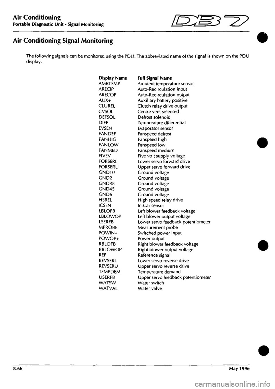
Air Conditioning
Portable Diagnostic Unit - Signal Monitoring 3^^?
Air Conditioning Signal Monitoring
The following signals can be monitored using the PDU. The abbreviated name of the signal is shown on the PDU
display.
Display Name Full Signal Name
AMBTEMP Ambient temperature sensor
ARECIP Auto-Recirculation input
ARECOP Auto-Recirculation output
AUX+ Auxiliary battery positive
CLUREL Clutch relay drive output
CVSOL Centre vent solenoid
DEFSOL Defrost solenoid
DIFF Temperature differential
EVSEN Evaporator sensor
FANDEF Fanspeed defrost
FANHIG Fanspeed high
FAN LOW Fanspeed low
FANMED Fanspeed medium
FIVEV Five volt supply voltage
FORSERL Lower servo forward drive
FORSERU Upper servo forward drive
GND10 Ground voltage
GND2 Ground voltage
GND38 Ground voltage
GND45 Ground voltage
GND6 Ground voltage
HSREL High speed relay drive
ICSEN In-Car sensor
LBLOFB Left blower feedback voltage
LBLOWOP Left blower output voltage
LSERFB Lower servo feedback potentiometer
MPROBE Measurement probe
POWIN+ Switched power input
POWOP+ Power output
RBLOFB Right blower feedback voltage
RBLOWOP Right blower output voltage
REF Reference signal
REVSERL Lower servo reverse drive
REVSERU Upper servo reverse drive
TEMPDEM Temperature demand
USERFB Upper servo feedback potentiometer
WATSW Water switch
WATVAL Water valve
8-66 May 1996
Page 345 of 421

Air Conditioning
Portable Diagnostic Unit - Signal Definitions ^27
Defrost Solenoid
(DEFSOL)
Temperature Differential
(DIFF)
Evaporator Sensor
(EVSEN)
Fanspeed Defrost
(FANDEF)
Fanspeed High
(FANHIG)
Fanspeed Low
(FAN LOW)
A/CCM Pin 11 ref Pin 6
The defrost solenoid controls the operation ofthe screen vents. When the solenoid
is energised, the screen vents will be held closed by the vacuum created. To open
the vents the solenoid is de-energised.
The solenoid is energised when a ground supply is provided to pin 11. The
solenoid is de-energised when the ground supply is removed, at which point 10+
volts can be read at pin 11.
A/CCM Pin 28 ref Pin 6
This sets the differential between the position ofthe upper and lower flaps. With
minimum differential selected, pin 28 should read between 0 and 100 millivolts.
The voltage at pin 28 will rise smoothly as the differential is increased, up to a
maximum of 2.885 volts.
A/CCM Pin 5 ref Pin 6
This sensor monitors the temperature of the evaporator matrix, the output is used
to trigger the compressor circuit via the A/CCM pin 20. Operating conditions are
2.732 volts at 0 degrees Celsius ±0.01 volts for every degree Celsius above or
below zero.
A/CCM Pin 27 ref Pin 6
This signal is normal ly held at 3.6 ±0.8 volts by the control module. When Defrost
is selected from the control panel, the line is pulled down to 0.6 volts or below.
This will cause the defrost flaps to open by applying system voltage (approx 11
volts) to pin
11.
In addition, both fans will go to full speed i.e. high speed fan relay
energised .
A/CCM Pin 15 ref Pin 6
This signal is generated from the fan speed control switch.
Switch at High, pin
1
5 should read 0.6 volts.
Switch at Off, L, M or D positions, pin 15 should read 3.6 ±0.8 volts.
A/CCM Pin 13 ref Pin 6
This signal is generated from the fanspeed control switch.
Switch at Low, pin 13 should read 0.6 volts.
Switch at Off, M, H or D positions, pin 13 should read 3.6 ±0.8 volts.
8-68 May 1996