window ASTON MARTIN DB7 1997 Workshop Manual
[x] Cancel search | Manufacturer: ASTON MARTIN, Model Year: 1997, Model line: DB7, Model: ASTON MARTIN DB7 1997Pages: 421, PDF Size: 9.31 MB
Page 9 of 421
[Em^^^?
Electrics
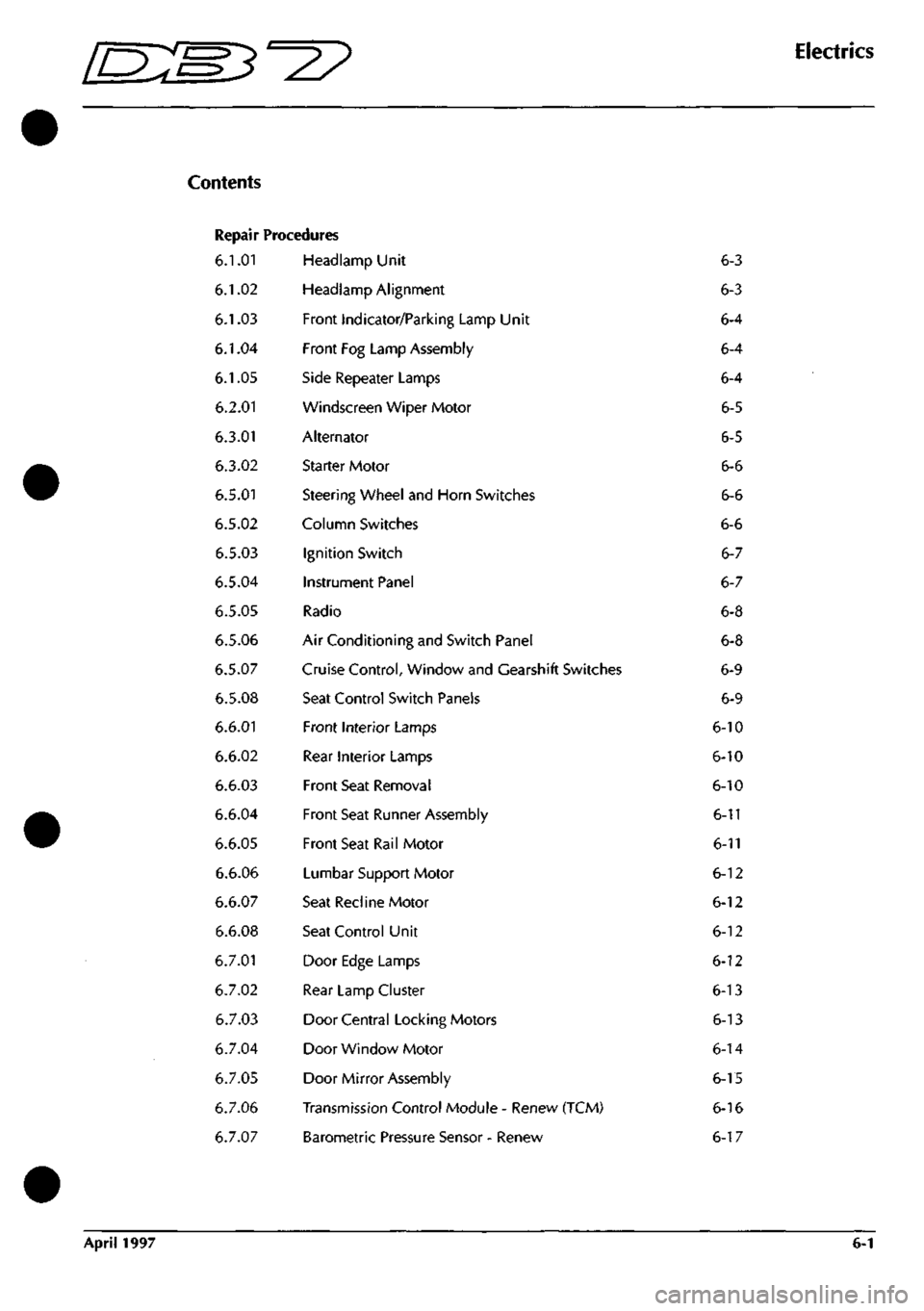
Repair Procedures
6.1.01
6.1.02
6.1.03
6.1.04
6.1.05
6.2.01
6.3.01
6.3.02
6.5.01
6.5.02
6.5.03
6.5.04
6.5.05
6.5.06
6.5.07
6.5.08
6.6.01
6.6.02
6.6.03
6.6.04
6.6.05
6.6.06
6.6.07
6.6.08
6.7.01
6.7.02
6.7.03
6.7.04
6.7.05
6.7.06
6.7.07
Headlamp Unit
Headlamp Alignment
Front Indicator/Parking Lamp Unit
Front Fog Lamp Assembly
Side Repeater Lamps
Windscreen Wiper Motor
Alternator
Starter Motor
Steering Wheel and Horn Switches
Column Switches
Ignition Switch
Instrument Panel
Radio
Air Conditioning and Switch Panel
Cruise Control, Window and Gearshift Switches
Seat Control Switch Panels
Front Interior Lamps
Rear Interior Lamps
Front Seat Removal
Front Seat Runner Assembly
Front Seat Rail Motor
Lumbar Support Motor
Seat Recline Motor
Seat Control Unit
Door Edge Lamps
Rear Lamp Cluster
Door Central Locking Motors
Door Window Motor
Door Mirror Assembly
Transmission Control Module - Renew (TCM)
Barometric Pressure Sensor - Renew
6-3
6-3
6-4
6-4
6-4
6-5
6-5
6-6
6-6
6-6
6-7
6-7
6-8
6-8
6-9
6-9
6-10
6-10
6-10
6-11
6-11
6-12
6-12
6-12
6-12
6-13
6-13
6-14
6-15
6-16
6-17
April 1997 6-1
Page 17 of 421
lEM^-^?
Electrics
Control Switch - Removal Procedures
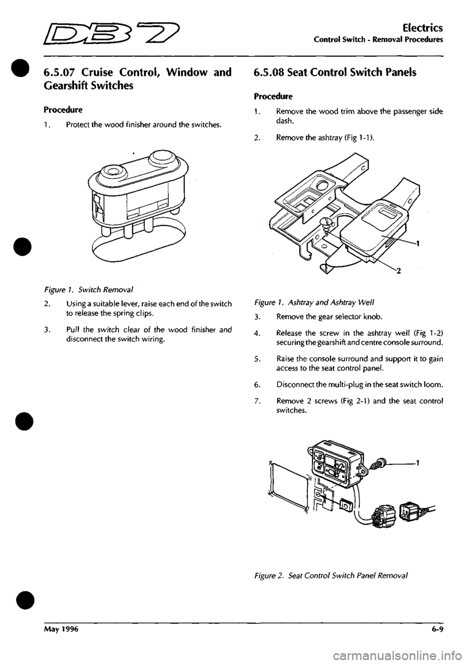
6.5.07 Cruise Control, Window and
Gearshift Switches
Procedure
1.
Protect the wood finisher around the switches.
6.5.08 Seat Control Switch Panels
Procedure
1.
Remove the wood trim above the passenger side
dash.
2.
Remove the ashtray (Fig
1
-1).
Figure 7. Switch Removal
2.
Using a suitable lever, raise each end of the switch
to release the spring clips.
3. Pull the switch clear oi the wood finisher and
disconnect the switch wiring.
Figure!. Ashtray and Ashtray Well
3. Remove the gear selector knob.
4.
Release the screw in the ashtray well (Fig 1-2)
securing the gearshift and centre console surround.
5. Raise the console surround and support it to gain
access to the seat control panel.
6. Disconnect the multi-plug in the seat switch loom.
7. Remove 2 screws (Fig 2-1) and the seat control
switches.
Figure 2. Seat Control Switch Panel Removal
May 1996 6-9
Page 22 of 421
Electrics
Electric Windows - Fault Analysis / Window Motor Removal
[n:m3^^
Electric Windows
Description
Power to the window wind circuits is available
when the ignition switch is on and is supplied
through a thermal cut-out to the left and right
window switches. The switches are double pole
plus earth so that the current through a window
motor may be switched in either direction to raise
or lower the window.
DB7 uses frameless door windows which seal
against rubber strips around the body shell door
opening.
To avoid damaging these seals during
door opening, the door glass must be lowered
before the door can be opened. This function is
controlled by the window control units. The units
are mounted on the inside of each door frame and
will sense if a door handle is pulled to open the
door. Before releasing the door lock, the control
unit will drive the window wind motor briefly to
lower the door window glass down until it clears
the window seals. Similarly, after closing a door,
the window motor will be run to raise the door glass
to seat the glass against the body seals.
Fault Analysis Procedure
a) If a window fails to operate, check for fuse failure
and the connectors for poor or open contacts.
b) Check the thermal cut-out by shorting across it and
operating either window. If the windows operate
with the short
ci rcu
it but not without, the cut-out is
faulty.
c) With the ignition on, battery voltage should be
available between the inputterminalsof the switches
and chassis. Operate each switch and ensure that
battery voltage is available between the switch
output terminals and chassis.
d) Measure voltagefrom each switch inputterminalto
the switch earth return terminal. If no voltage is
measured,
the earth return line is open circuit.
e) Measure continuity through the wiring from the
switches to each motor. If continuity is correct,
remove the motor for bench testing.
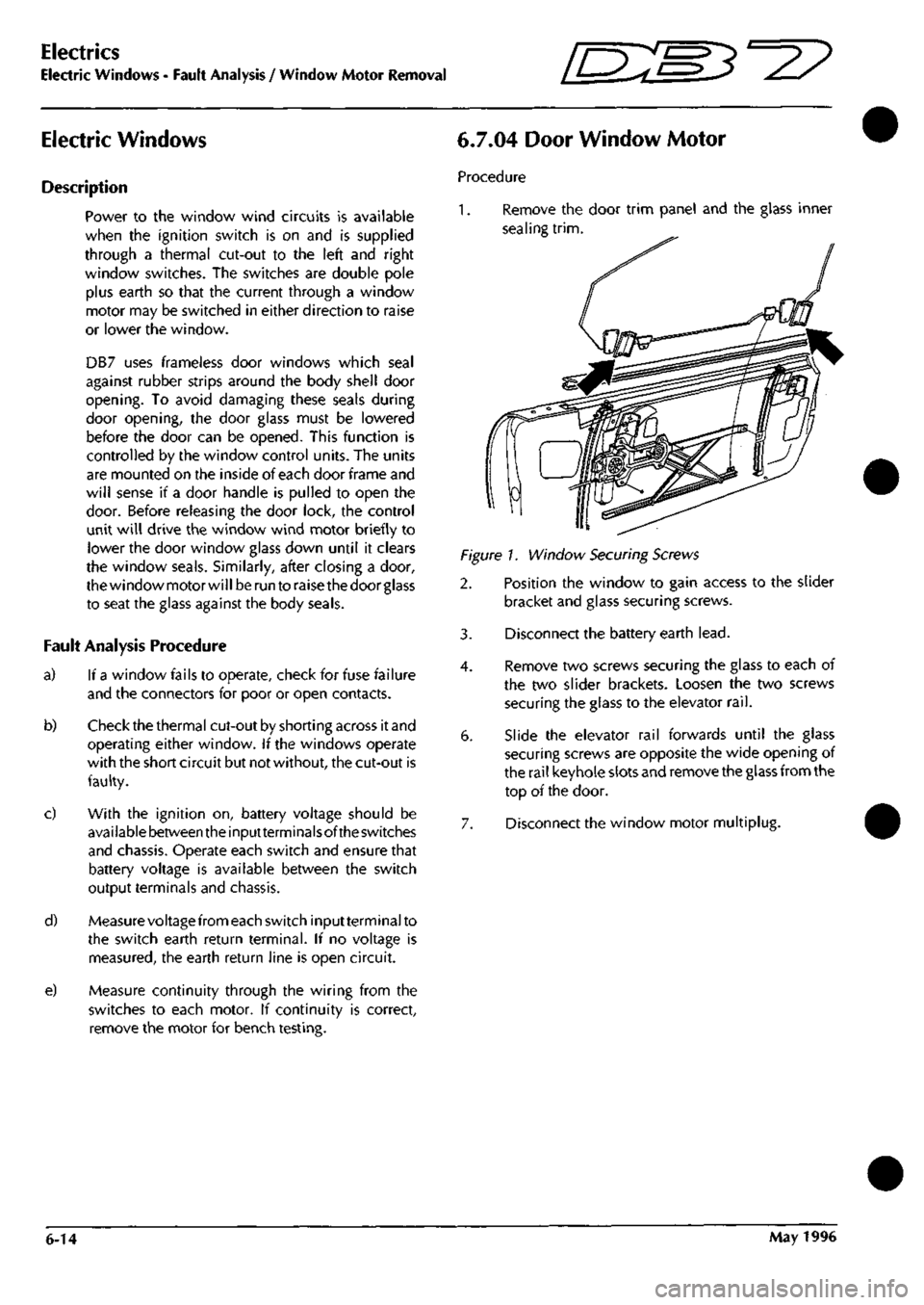
6.7.04 Door Window Motor
Procedure
1.
Remove the door trim panel and the glass inner
sealing
trim.
Figure!. Window Securing Screws
2. Position the window to gain access to the slider
bracket and glass securing screws.
3. Disconnect the battery earth
lead.
4.
Remove two screws securing the glass to each of
the two slider brackets. Loosen the two screws
securing the glass to the elevator
rail.
6. Slide the elevator rail forwards until the glass
securing screws are opposite the wide opening of
the rail keyhole slots and remove the glass from the
top of the door.
7. Disconnect the window motor multiplug.
6-14 May 1996
Page 29 of 421
[n:m3^y
Component Name
Microwave Sensor
Mode Switch
Multifunction Module
Number Plate Lamp - LH
Number Plate Lamp - RH
Oil Pressure Warning Light Transducer
Output Speed Sensor (Auto)
Park Switch (Auto)
Purge Valve 1
Purge Valve 2
Radio Aerial
Radio Telephone Connector
Radio Tweeter
Radio Tweeter
Radio
Rear & Number Plate Bulb Fail Unit
Rear Fog Lamp LH
Rear Fog Lamp RH
Rear Lamp - LH
Rear Lamp - RH
Recline Motor Potentiometer
Relay - ABS Pump
Relay - Air conditioning clutch
Relay - Air Pump
Relay - Auxiliary Load
Relay - Boot Release
Relay - Courtesy Lights
Relay - Cruise Control On/Off
Relay - Drivers Seat Heater
Relay - Fan 1
Relay - Fan 2
Relay - Fan Run On
Relay - Front Fog Lamps
Relay - Fuel Pump 1
Relay - Fuel Pump 2
Relay - Gearbox Failure Warning
Relay - Headlamp Dipped Beam
Relay - Headlamps
Relay - Heated Rear Window
Relay - Horns
Relay - Ignition Load
Relay - Main
)
Location
Reference
12-1
7-9
4-2
5-3
5-3
3-17
11-12
10-1
10-3
10-4
15-4
15-3
6-7
6-5
6-6
15-11
14-2
14-5
14-1
14-6
9-7
4-8
1-17
4-14
4-4
15-9
4-11
6-1
12-3
1-20
1-19
1-18
1-6
15-7
15-8
4-9
1-5
1-7
4-15
1-16
4-10
4-12
Relays - Drivers/Passengers Seat Heaters 12-3
Relay - Rear Fog Lamps
Relay - Reverse Lamps
Relay - Sidelamps
Relay - Starter Solenoid
Relay - Stop Lamps
Reversing Lamp Switch (Man)
Reversing Light Switch (Auto)
Screen Wash Pump
4-17
15-6
1-9
1-15
15-5
11-3
10-2
1-13
Electrics
Electrical Component Location Index - Up to 97 MY
Wiring Diag.
Reference
24-C2
4-A3
8-C4
27-84
27-B6
5-C5
7-B3
21-B1
5-A4
5-A5
24-D2
25-B2
8-C3
14-C4
10-A2
25-C3
17-D2
18-D2
24-A5
24-C4
22-81
9-C4
3-A3
13-A5
9-D1
26-D3
13-A2
20-B1
16-D3
3-B6
3-B6
3-A5
1-B5
26-A2
26-A3
13-A1
1-B5
1-84
13-A4
3-A4
13-A2
13-A3
15-D3
13-A5
25-A4
1-B4
3-A4
25-A5
7-C5
21-C2
3-D1
Rep.
Op. Notes
Reference
6.6.14.2
6.5.07.4
6.4.12.1
6.9.03.1
6.9.03.1
1.5.08.1
3.4.02.2
Auto only
6.5.13.1
Auto only
6.1.14.1
6.1.14.2
6.9.08.1
6.9.09.1
6.5.17.1
6.5.17.1
6.5.05.1
6.9.10.1
6.7.02.1
6.6.07.1
5.1.15.1
6.2.06.1
6.4.13.1
6.4.14.1
6.9.11.1
6.4.15.1
6.5.18.1
6.6.15.1
1.7.16.3
1.7.16.3
1.7.16.4
6.1.04.3
6.9.12.1
6.9.12.1
6.4.16.1
Auto only
6.1.15.1
6.1.16.1
6.4.17.1
6.2.07.1
6.4.18.1
6.4.19.1
6.6.15.2
6.4.20.1
6.9.13.1
6.1.17.1
6.2.08.1
6.9.14.1
6.2.09.1
6.2.09.2
6.3.06.1
May 1996 6-21
Page 30 of 421
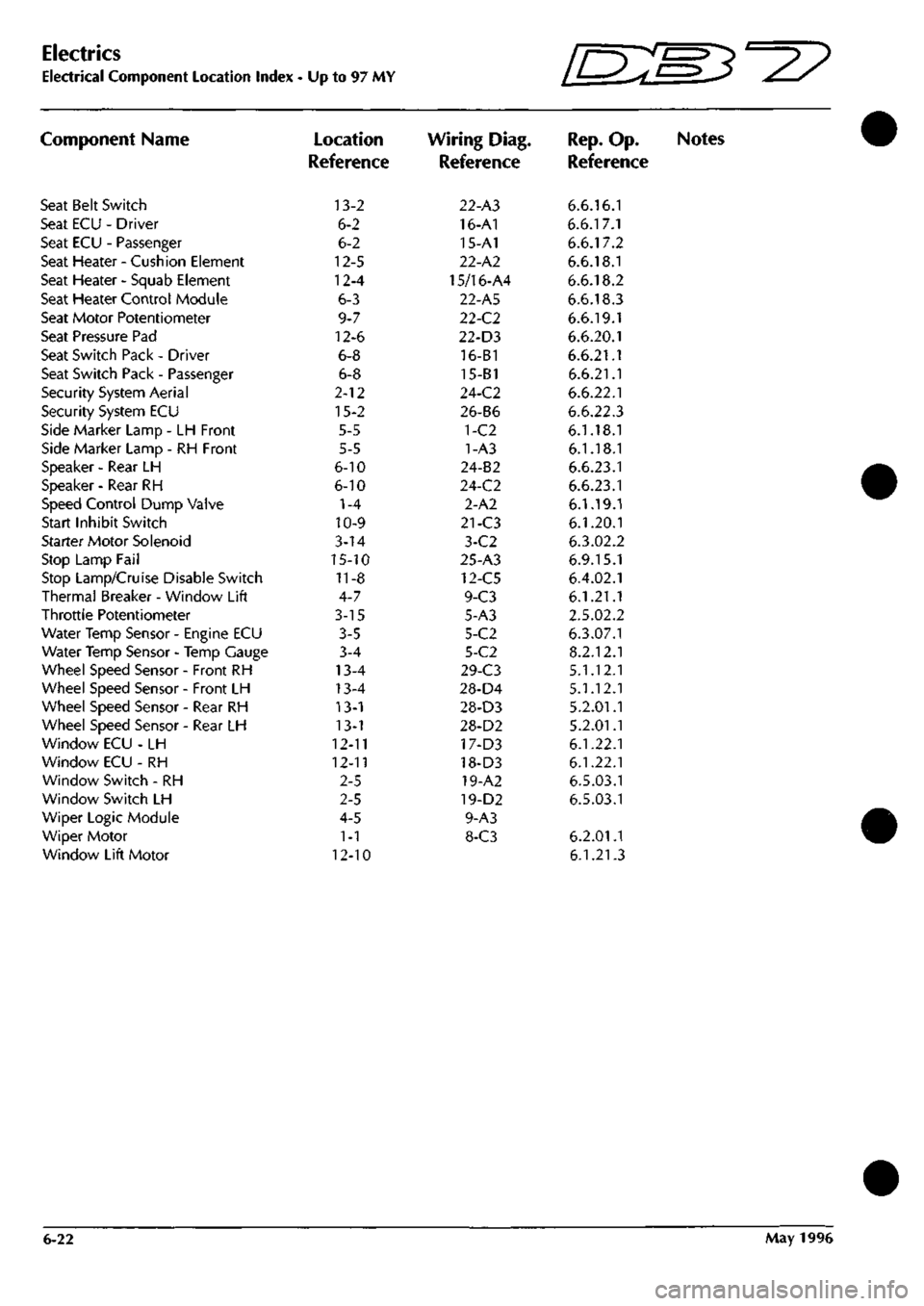
Electrics
Electrical Component Location Index - Up to 97 MY
Component Name
Seat Belt Switch
Seat ECU - Driver
Seat ECU - Passenger
Seat Heater - Cushion Element
Seat Heater - Squab Element
Seat Heater Control Module
Seat Motor Potentiometer
Seat Pressure Pad
Seat Switch Pack - Driver
Seat Switch Pack - Passenger
Security System Aerial
Security System ECU
Side Marker Lamp - LH Front
Side Marker Lamp - RH Front
Speaker - Rear LH
Speaker - Rear RH
Speed Control Dump Valve
Start Inhibit Switch
Starter Motor Solenoid
Stop Lamp Fail
Stop Lamp/Cruise Disable Switch
Thermal Breaker - Window Lift
Throttle Potentiometer
Water Temp Sensor - Engine ECU
Water Temp Sensor - Temp Gauge
Wheel Speed Sensor - Front RH
Wheel Speed Sensor - Front LH
Wheel Speed Sensor - Rear RH
Wheel Speed Sensor - Rear LH
Window ECU - LH
Window ECU - RH
Window Switch - RH
Window Switch LH
Wiper Logic Module
Wiper Motor
Window Lift Motor
Location
Reference
13-2
6-2
6-2
12-5
12-4
6-3
9-7
12-6
6-8
6-8
2-12
15-2
5-5
5-5
6-10
6-10
1-4
10-9
3-14
15-10
11-8
4-7
3-15
3-5
3-4
13-4
13-4
13-1
13-1
12-11
12-11
2-5
2-5
4-5
1-1
12-10
Wiring Diag.
Reference
22-A3
16-A1
15-A1
22-A2
15/16-A4
22-A5
22-C2
22-D3
16-B1
15-B1
24-C2
26-B6
1-C2
1-A3
24-B2
24-C2
2-A2
21-C3
3-C2
25-A3
12-C5
9-C3
5-A3
5-C2
5-C2
29-C3
28-D4
28-D3
28-D2
17-D3
18-D3
19-A2
19-D2
9-A3
8-C3
Rep.
Op.
Reference
6.6.16.1
6.6.17.1
6.6.17.2
6.6.18.1
6.6.18.2
6.6.18.3
6.6.19.1
6.6.20.1
6.6.21.1
6.6.21.1
6.6.22.1
6.6.22.3
6.1.18.1
6.1.18.1
6.6.23.1
6.6.23.1
6.1.19.1
6.1.20.1
6.3.02.2
6.9.15.1
6.4.02.1
6.1.21.1
2.5.02.2
6.3.07.1
8.2.12.1
5.1.12.1
5.1.12.1
5.2.01.1
5.2.01.1
6.1.22.1
6.1.22.1
6.5.03.1
6.5.03.1
6.2.01.1
6.1.21.3
Notes
6-22 May 1996
Page 47 of 421
#
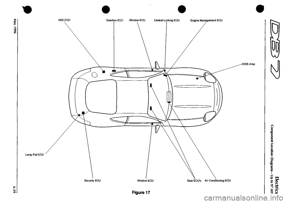
ABS ECU Gearbox ECU Window ECU Central Locking ECU Engine Management ECU
Lamp Fail ECU
EDIS Amp
Security ECU Window ECU Seat ECU'S Air Conditioning ECU
Figure 17
o
o 3 •a o 3 n 3 O n Si 5 3
ere
3
c
•o
o
-<
n
Page 67 of 421
NO COLOUR 4
NP
5
VS
14
WU
17
GW
51
RO
61
BR
65
UB
70
yw
71
YB
77
RS
79
RG
83
WK
66
BK
87
YR
90
OR
91
W
92
NR
95
R
94
RY
95
U
96
UW
97
OY
98
YP
99
YO
121
m
156 UB 138 RN 198 GN 207
NB
209
OK
222 OS 226 BH 248
NS
249
LGO
250
WS
252
WY
253
UG
255
G
258
KB
259
OR
260
0
261
NR
262 BLG 263
WR
520
P
321 PW 322 RU 323
GU
324
Y
325
LG
328
RN
330 YC 331
YU
336 W 340 B 346 NW 347 NY 351 V«U 352
W
354
W
355
WR
AREA 03 A6 A6 A6 A6 B5-88 A6 A6 B6 C2-7I C2-7I B6 B6 B4-84 86 B4-66 86 B5-87 86 B6 86 86 86 B6 B6 B6 B6 86 B6 86 86 86 B6 83-77 C6 C6 C6 C6 C6 C6 C6 C6 C6 02 83-75 C6 C6 C6 C6 C6 C6 C6 C6 B4-86 A3 02 B3-76 C6 B4-ee C6 CG
NO COLOUB 356
WLG
357 8LC 558
BR
559 0
561 NK 362 RW 363 P 364 NG 366 WK 367 OW 366 OS 369 OU 372
BR
374
WR
575
NR
377
BG
578
BS
379
BY
380 PG 581 BP 582
WB
585 K 584
WP
385 8U 386 CO 387 BW 388 PS 405 NU 407 B 411
B
419 NB 430 P 447 KB 471 BW 472
B
473
B
510
B
536 8 551
B
552
B
565
B
604 NB 618
8
622
KB
699 NU 715
BK
717
OU
718 OW
AREA A2 A2 A2 82-72
C2 C6 B3-75 C4 03-80 02 C6 C6 85-88 64-86 06 06 06 06 06 06 06 06 06 06 A6 A6 A6 C5 01 01 A2 02 04 86 B6 86 C6 C6 C6 C6 C6 C6 C6 C6 06 B4-85 D6 06
NO COLOUn 596 BK 397 W 398 N 399 NY
PIN 85 86 87 }0
AREA B4-85 84-86 A2
6?-m
AUX LOAD RELAY
^5^
HEATED FRONT SCREEN CONTROLER
N6
toLwk
l>lli
IRET
400 N
I B4
jiaaii
2__s!
HEATED FRONT SCREEN FOSE
40A
I
HI>
cALbUR AREA
I "PI if «t
WIPER LOGIC MODULE NO CdLOUt 340 B 415
0
416 LGG 417 LGW 418 LGN 357 BLG 356 WLG 358 BR 109 LGB
419 NB 420 LGP 421
LG
422
LGR
t2?B5
PIN 1 2 3 4 5 6 7 8 9 10 II 12 15 14 IS
'i
AREA
a
B2-72 B6 86 B6 Al Al Al 86
81 B6 86 86 86
-«•
SHEET
8
AREA
6
NO COLOUF 407 B 408 WK 409 WO
410
N
l>IH 85 86 87 87A
W
AREA Bl C5-80 B2-74
B?-'?
AUX LOAD RELAY
t_jRH
Fl
IFAIL
I
I I I
SPL
72
SPL
75
SPL
74 SPL 75
wmmrmr^m'
424
WP
U
C3-ei
SUM W H
1
H FRONT BULB FAIL MODULE
NO COLOUR 402 WS 405 R 404 RG
PIN AREA 86 85-87 «-7l
NO COLOUR AREA 405
NU
Bl
406 N
B4
SPL
86
SPL
88
I
I I I
NO COLOUR 400 N 406 N 428
N
444 N 465 N 465 N 466 N 467 N
AREA A2 C2 D2 02 04 84-83 B3-78 B3-79
SHEET
10
AREA
I
5>
6»
NO COLOUR 468 WP 469 WK 470 NU 464 NO
PIN 85 86 87
??
AREA C3-8I C3-80 B6 04
WINDOW LIFT THERMAL BREAKER
NO COLOUR 411
B
412 WK 413 WK
414
N
PIN 85 86 87 87A
59
AREA 81 C3-80 82-75
n.-.n
NO COLOUR
PIN
428 N 361 NK 429
N
450 P 451 N 346 NW 452 N 435 P 434 WO 435 WU 436 WK 437 LG 438 W 263
WR
439 W
4400
441
WO
367
OW
442 W 172 G 444 N ilLNL.
I 2 3 4 5 6 7 8 9 10 II 12 13 14 15 16 17 18 19 20 21 -22-
TRpr
B4 Al B3-79 81 83-82 CI B3-78 86 82-74 86 82-73 86 B6
CI
B6
82-72 B2-74 Al
B4-86
Be C4 .M-
M
3! n>
<^
3 oj
Ol
2 W
:*^
"^
— n>
"w
mm I^IN
446 N 464 NG 447 KB 174
KB
448 W 449WK 450 WK 451 LG 452
WX
453 GP 454
N
455 NP 456 N 457 NP 458 W 459 G 460 N 461
P
462 N 4
NP
463 N 464 NO
23 24 25 26 27 28 29 30 31 32 33 34 35 36 37 38 39 40 41 42 45 44
ARTT
B4-83 C6 81 86 B4-86 86 82-73 86 82-73 86 B3-82 86 83-79 B6 84-86 86 83-82 86 83-82 Al C4 C4
COLOUR YS WU GW RO
65
UB 70
YW
71
YB
83
WK
86
BK
90
GR
92
NR
94
RY
95
U
96
UW
97
GY
98
YP
99
YO
109 LGB 121
WR
131
YR
136 UB 138 RN 163 BK 172
G
174
KB
198 GN 207
NB
209
OK
222 OS 226 BN 248
NS
250
WS
252
WY
253
UG
255
G
258
KB
259
OR
260 0 261 NR 262 BLG 321
PW
322 RU
323
GU 324 Y
325
LG
328
RN
330 YG 331
YU
351 WU 354
W
355
WR
AREA 81 81 81 81 Bl 81 81 81 81 Bl 81 81 81 81 81 81 81 AS
CI
B4-84 CI CI C4-85 D3 04 CI CI CI CI
CI
CI CI CI CI CI CI CI CI CI CI CI CI CI CI Bl 81 81 81 Bl 81 Bl
362
RW
368 OS 369 OU 375
BY
377
BG
378 8S 379 BY 380 PG 381 BP 362
WB
383 K 384 WP
Bl CI CI CI CI CI CI Bl Bl 81 Bl 81
NO COLOUR 385 BU 586 00 587
GW
388 PS 401 BY 402 WS
416
LGG 417
LGN
418
LGN
420 LGR 421
LG
422
LOP
423
BS
425
WP
433 P 435 WU 437 LG 438 W 439 W 445 NG 449 WK 451 LG 455 GP 455 NP 457 NP 459 6 461
P
470 NU 471 BW 472
B
473 B 494 BR 498 P 505 LGO 510
B
522
YR
528
BK 536 6 537
W
551
8
552
B
555
W
565 B
566 NY 586 LGO 604 NB 608 0 616
P
618 B 622
KB
649 P 662 N 665 P 668 WO 687 NY 695 P 699 NU 710 R 712 W 714 WK
717
OU
718
OW
JD
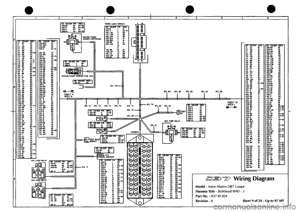
Wiring Diagram
Model
-
Aston Martin DB7 Coupe
Harness Title
-
Bulkhead RHD
- 2
Part No.-B37-81304
TRfT
Bl 81 82 C2 A2 A2 A2 A2 A2 A2 A2 C2 02 D2 02 D2 02 02 04 D4 04 D4 04 04 04 04
Bl Bl Bl
B5-88
85-75
85-77 CI B4-84 84-85 CI 84-86 CI CI
84-86
CI
85-76
B3-77
CI B4-72
83-75
CI CI B3-75 C4-83
B3-75
82-74
83-76
83-75
CI
B5-87
84-86
C3-80 CI .il
Revision -
0
Sheet
9
of 29
-
Up to 97 MY
Page 87 of 421
NO COLOUR
PIN
ARTT
492
YW
I B6
2 782
B ;
C3-I62 SECURITY SYSTEM VALET SWITCH
ffi
NO
COLOUf
786 8 787
RW
788 B 948 RG 549 CR
PIN 1
1
5 6
.7...
tittA
C3-I62 85-161
C3-I62
B6
-Si
RH WINDOW SWITCH
LH WINDOW SWITCH NO COLOUR
PIN
763 B 784
RW
785
8
322 RU 3g3GU
AREA
C3-I62 85-161
C3-I62
B6
-££.
c^
®
CIGAR LIGHTER
GEAR SELECTOR ILLUMINATION
NO COLOUR
PIN
ABEA"
778
RW I
B5-I6I
iI2J
2
tM?2l
NO COLOUR
PIN
ARET
I
548 RG
549 6R
322 RU
323
GU
453 GP
550
RW
2 3 4 5 6 7 6 9 10 II 12 13 14 15
JS-
A2 A2 02 02 D3 BS-I6I
NO COLOUR
PIN 780
B
I 453 GP 2
781
RW
AREA C3-162
B6
B5-I6I
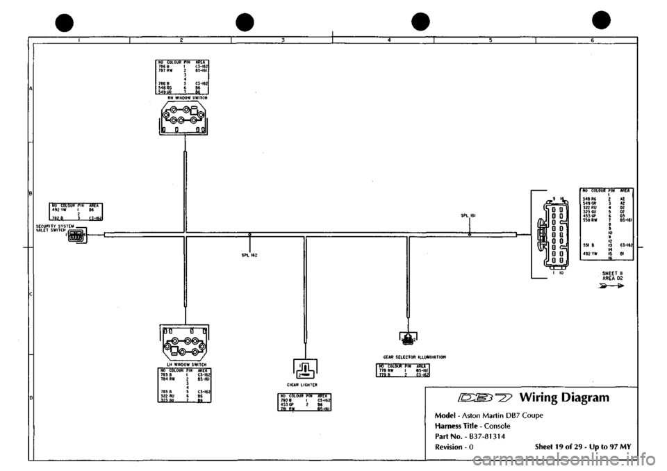
°27 Wiring Diagram
Model
-
Aston Martin
DB7
Coupe
Harness Title
-
Console
PartNo.-B37-81314
Revision
- 0
Sheet
19 of 29 - Up to 97 MY
Page 110 of 421
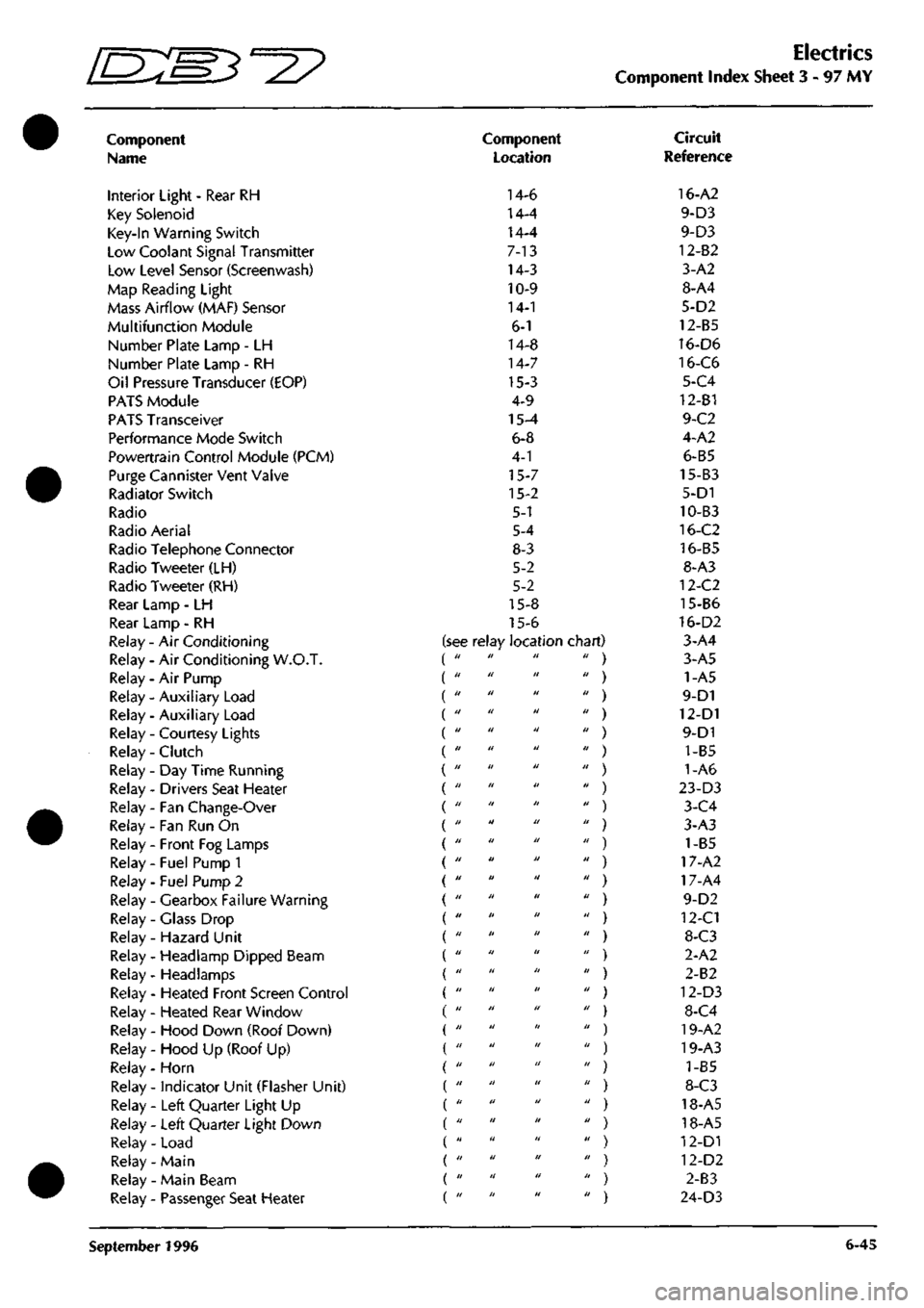
Electrics
Component Index Sheet 3 - 97
MY
Component
Name
Interior Light - Rear RH
Key Solenoid
Key-In Warning Switch
Low Coolant Signal Transmitter
Low Level Sensor (Screenwash)
Map Reading Light
Mass Airflow (MAF) Sensor
Multifunction Module
Number Plate Lamp - LH
Number Plate Lamp - RH
Oil Pressure Transducer (EOP)
PATS Module
PATS Transceiver
Performance Mode Switch
Powertrain Control Module (PCM)
Purge Cannister Vent Valve
Radiator Switch
Radio
Radio Aerial
Radio Telephone Connector
Radio Tweeter (LH)
Radio Tweeter (RH)
Rear Lamp - LH
Rear Lamp - RH
Relay - Air Conditioning
Relay - Air Conditioning W.O.T.
Relay - Air Pump
Relay - Auxiliary Load (
Relay - Auxiliary Load (
Relay - Courtesy Lights (
Relay - Clutch (
Relay-Day Time Running (
Relay - Drivers Seat Heater (
Relay - Fan Change-Over (
Relay - Fan Run On
Relay - Front Fog Lamps
Relay - Fuel Pump 1
Relay - Fuel Pump 2
Relay - Gearbox Failure Warning
Relay - Glass Drop
Relay - Hazard Unit
Relay - Headlamp Dipped Beam
Relay- Headlamps
Relay - Heated Front Screen Control
Relay - Heated Rear Window
Relay - Hood Down (Roof Down)
Relay - Hood Up (Roof Up)
Relay - Horn
Relay - indicator Unit (Flasher Unit)
Relay - Left Quarter Light Up
Relay - Left Quarter Light Down
Relay - Load
Relay- Main
Relay - Main Beam
Relay - Passenger Seat Heater
Component
Location
14-6
14-4
14-4
7-13
14-3
10-9
14-1
6-1
14-8
14-7
15-3
4-9
15-4
6-8
4-1
15-7
15-2
5-1
5-4
8-3
5-2
5-2
15-8
15-6
see relay location chart) di II II II
II II II II
II II II II
11 II II II
II II II II
II II II II
II II II II
II II II II
II II II II
11 II II II
II II II II
II II II II
II II It II
II II II II
11 II II II
II II II II
II II II II
II II II II
II II II II
II It II II
II II II II
11 II II II
II II II II
11 II II II
11 II II II
II II II II
II II II II
II II II II
II II II II
II II II II
Circuit
Reference
16-A2
9-D3
9-D3
12-82
3-A2
8-A4
5-D2
12-B5
16-D6
16-C6
5-C4
12-B1
9-C2
4-A2
6-B5
15-B3
5-D1
10-B3
16-C2
16-B5
8-A3
12-C2
15-B6
16-D2
3-A4
3-A5
1-A5
9-D1
12-D1
9-D1
1-B5
1-A6
23-D3
3-C4
3-A3
) 1-B5
) 17-A2
) 17-A4
9-D2
) 12-C1
) 8-C3
2-A2
) 2-B2
) 12-D3
) 8-C4
) 19-A2
) 19-A3
) 1-85
) 8-C3
) 18-A5
) 18-A5
) 12-D1
) 12-D2
) 2-83
) 24-D3
September 1996 6-45
Page 111 of 421
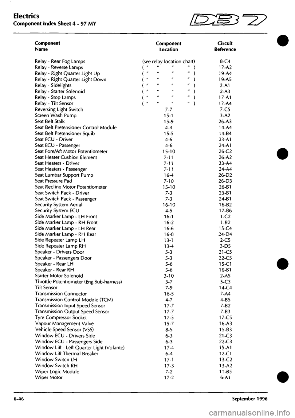
Electrics
Component Index Sheet 4-97 MY ^7
Component
Name
Relay - Rear Fog Lamps
Relay - Reverse Lamps
Relay - Right Quarter Light Up
Relay - Right Quarter Light Down
Relay - Sidelights {
Relay - Starter Solenoid
Relay - Stop Lamps
Relay- Tilt Sensor
Reversing Light Switch
Screen Wash Pump
Seat Belt Stalk
Seat Belt Pretensioner Control Module
Seat Belt Pretensioner Squib
Seat ECU - Driver
Seat ECU - Passenger
Seat Fore/Aft Motor Potentiometer
Seat Heater Cushion Element
Seat Heaters - Driver
Seat Heaters - Passenger
Seat Lumbar Support Pump
Seat Pressure Pad
Seat Recline Motor Potentiometer
Seat Switch Pack - Driver
Seat Switch Pack - Passenger
Security System Aerial
Security System ECU
Side Marker Lamp - LH Front
Side Marker Lamp - RH Front
Side Marker Lamp - LH Rear
Side Marker Lamp - RH Rear
Side Repeater Lamp LH
Side Repeater Lamp RH
Speaker - Drivers Door
Speaker - Passengers Door
Speaker - Rear LH
Speaker - Rear RH
Starter Motor Solenoid
Throttle Potentiometer (Eng Sub-harness)
Tilt Sensor
Transmission Connector
Transmission Control Module (TCM)
Transmission Input Speed Sensor
Transmission Output Speed Sensor
Tyre Compressor Socket
Vapour Management Valve
Vehicle Speed Sensor (VSS)
Window ECU - Drivers Side
Window ECU - Passengers Side
Window Lift - Left Quarter Light (Volante)
Window Lift Thermal Breaker
Window Switch LH
Window Switch RH
Wiper Logic Module
Wiper Motor
6-46
Component
Location
Circuit
Reference
(see relay location chart) 8-C4 it ti It
II H U
tl 11 U
a II 11
II II II
II Ji II
II II II
7-7
15-1
15-9
4-4
15-5
4-6
4-6
15-10
7-11
7-n
7-11
16-4
7-10
15-10
7-3
7-3
16-10
4-5
16-1
16-2
16-6
16-8
13-1
13-4
5-3
5-3
5-6
5-6
3-10
3-7
7-9
16-5
4-7
17-7
17-7
17-5
15-7
8-5
6-3
6-3
17-4
6-4
17-1
17-3
7-2
17-2
' ) 17-A2
' ) 19-A4
' ) 19-A5
' ) 2-A1
' ) 2-A3
' ) 17-A1
' ) 17-A4
7-C5
3-A2
26-A3
14-A4
14-B4
23-A1
24-A1
26-C2
26-A2
23-A4
24-A4
26-D2
26-D3
26-B1
23-B1
24-B1
16-B2
17-B6
1-C2
1-82
15-C4
24-D4
2-C5
3-D5
21-C5
22-C5
15-Cl
16-B1
2-A5
5-C3
14-C4
7-A4
4-B5
7-B2
7-B3
17-C5
16-A3
15-B3
21-C3
22-C3
15-A1
12-Cl
13-C2
13-A2
11-B5
6-A1
September 1996