differential ASTON MARTIN DB7 1997 Workshop Manual
[x] Cancel search | Manufacturer: ASTON MARTIN, Model Year: 1997, Model line: DB7, Model: ASTON MARTIN DB7 1997Pages: 421, PDF Size: 9.31 MB
Page 278 of 421
in:!M3^^?
Air Conditioning
Contents
Contents
General Description 8-5
Specifications 8-5
Climate Control System 8-6
System Description 8-7
Special Servicing Tools and Equipment 8-7
Working Practices 8-8
General 8-8
Handling Refrigerant 8-8
Handling Lubricating Oil 8-8
System Maintenance 8-8
Temperature Distribution System 8-9
Fan Speed Control (Mode Switch) 8-10
Face Level Temperature Differential 8-10
Temperature Rotary Control 8-10
Refrigeration Cycle 8-11
System Protection 8-12
General System Procedures 8-12
Leak Test 8-12
Charge Recovery (System Depressurisation) 8-12
Evacuating the System 8-13
Adding Compressor Lubricating Oil 8-13
Adding Refrigerant 8-14
Functional Check 8-15
System Trouble Shooting 8-1 7
Electronic Control Module (ECM) 8-19
In Car Controls 8-21
Temperature Demand Switch 8-21
Face Level Differential Controller 8-21
Air Conditioning Function Switch 8-22
Fan Speed Control Switch (Mode Switch) 8-23
Temperature Sensors 8-23
Evaporator Sensor 8-24
Motorised In-Car Aspirated Sensor 8-24
Water Temperature Switch 8-25
Blower Motors 8-25
Potentiometers 8-26
Servo Motors 8-27
Vacuum System 8-28
Pressure-Temperature Graphs 8-29
May 1996 8-1
Page 287 of 421
Air Conditioning
Temperature Distribution System
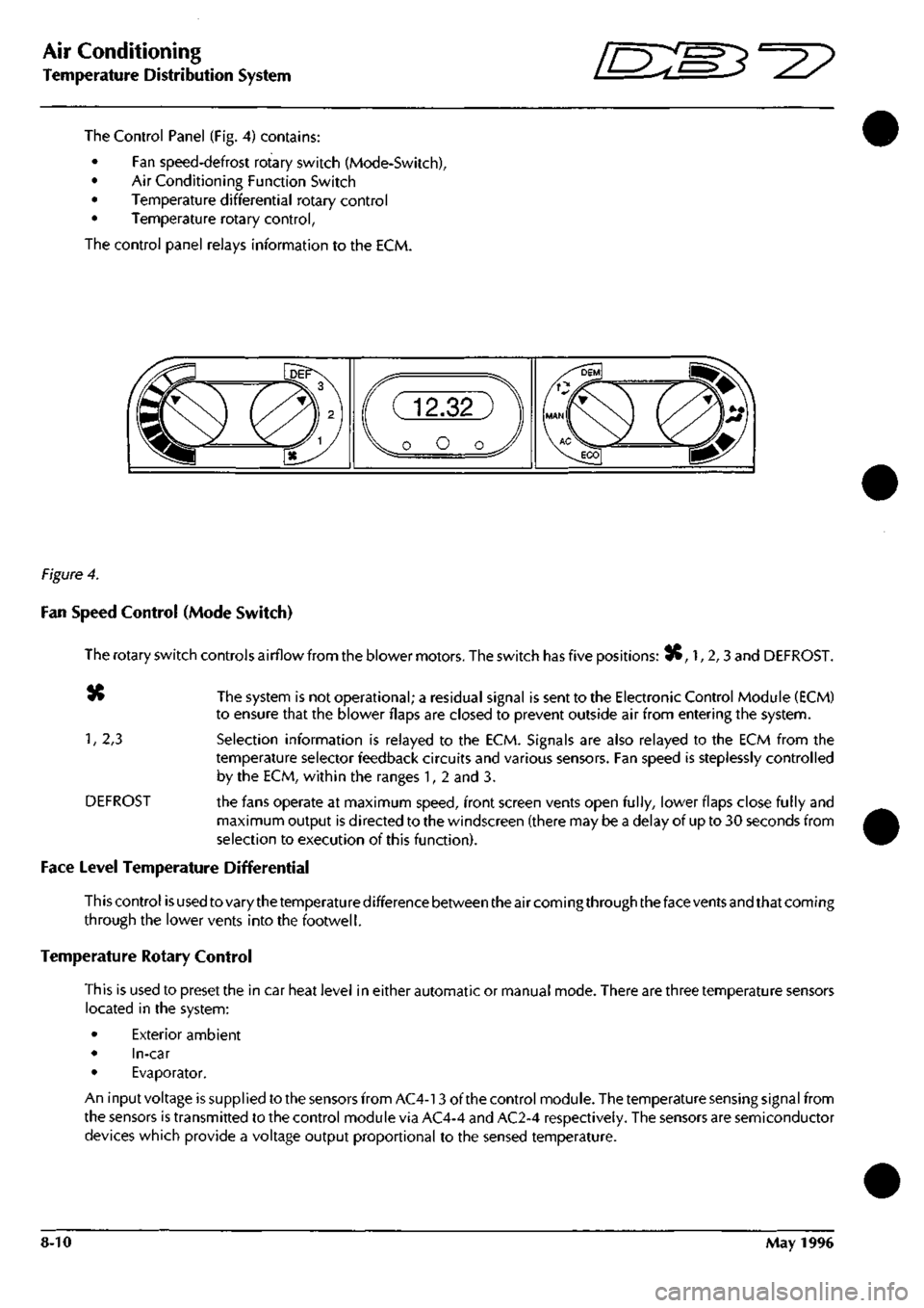
The Control Panel (Fig. 4) contains:
• Fan speed-defrost rotary switch (Mode-Switch),
• Air Conditioning Function Switch
• Temperature differential rotary control
• Temperature rotary control,
The control panel relays information to the ECM.
Figure 4.
Fan Speed Control (Mode Switch)
The rotary switch controls airflow from the blower motors. The switch has five positions: 3C, 1, 2,3 and DEFROST.
«» The system is not operational; a residual signal is sent to the Electronic Control Module (ECM)
to ensure that the blower flaps are closed to prevent outside air from entering the system.
1,
2,3 Selection information is relayed to the ECM. Signals are also relayed to the ECM from the
temperature selector feedback circuits and various sensors. Fan speed is steplessly controlled
by the ECM, within the ranges 1, 2 and 3.
DEFROST the fans operate at maximum speed, front screen vents open fully, lower flaps close fully and
maximum output is directed to the windscreen (there may be a delay of up to 30 seconds from
selection to execution of this function).
Face Level Temperature Differential
This control is used to vary the temperature difference between the air coming through the face vents and that coming
through the lower vents into the footwell.
Temperature Rotary Control
This is used to preset the in car heat level in either automatic or manual mode. There are three temperature sensors
located in the system:
• Exterior ambient
• In-car
• Evaporator.
An input voltage is supplied to the sensors from AC4-13 of the control module. The temperature sensing signal from
the sensors is transmitted to the control module via AC4-4 and AC2-4 respectively. The sensors are semiconductor
devices which provide a voltage output proportional to the sensed temperature.
8-10 May 1996
Page 289 of 421
Air Conditioning //~-->> ^/zz:^^ • ^ ^
General Svstem Procedures ' —"^ ^ '^ General System Procedures
From the condenser the liquid passes into the Receiver-Drier which has three functions:
• Storage vessel for varying system refrigerant demands.
• Filter to remove system contaminants.
• Moisture removal via the desiccant.
With the passage through the receiver-drier completed the, still high pressure liquid refrigerant, enters the Expansion
Valve where it is metered through a controlled orifice which has the effect of reducing the pressure and temperature.
The refrigerant, now in a cold atomised state, flows into the Evaporator and cools the air which is passing through
the matrix.
As heat is absorbed by the refrigerant it once again changes state, into a vapour, and returns to the compressor for
the cycle to be repeated (Fig. 5).
There is an automatic safety valve incorporated in the compressor which operates should the system pressure be
in excess of
41
bar. The valve re-seats when the pressure drops below 35 bar.
Note: The division of HIGH and LOW side is simply the
system pressure
differential created by the
compressor
discharge
(pressure),
suction
(inlet)
ports and
the
relative inlet and outlet
ports
of the
expansion
valve.
This
differential is critical to
system
fault
diagnosis
and efficiency checks.
System Protection
The trinary pressure switch, located in the liquid line, cuts electrical power to the compressor clutch if the system
pressure is outside of the range of 2 Bar
(1
st Function) to 27 Bar (2nd Function). The third function is to switch on
the cooling fans when pressure exceeds 20 bar.
General System Procedures
Leak Test
Faults associated with low refrigerant charge weight and low pressure may be caused by leakage. Leaks traced to
mechanical connections may be caused by torque relaxation or joint face contamination. Evidence of oil around
such areas is an indicator of leakage. When checking for non visible leaks use only a dedicated Refrigerant El 34A
electronic analyser and apply the probe all round the joint connection. Should a leak be traced to a joint, check that
the fixing is secured to the correct tightening torque before any other action is taken.
Do not forget to check the compressor shaft seal and evaporator.
Note: Never
use
a dedicated
CFC 12
or
naiced
flame type
analyser.
Charge Recovery (System Depressurisation)
The process of refrigerant recovery depends on the basic characteristics of your chosen recovery-recycle-recharge
equipment, therefore, follow the manufacturers instructions carefully. Remember that compressor oil may be drawn
out of the system by this process, take note of the quantity recovered so that it may be replaced.
CAUTION: Observe all relevant safety requirements.
• Do not vent refrigerant directly to atmosphere and always use approved recovery-recycle-recharge
equipment.
• Wear suitable eye and skin protection.
• Do not mix the refrigerant with CFC 12.
• Take note of the amount of recovered refrigerant, it indica
tes the
state of the
system
and
thus the
magnitude
of any problem.
8-12 May 1996
Page 292 of 421
Air Conditioning
Functional Check
Functional Check
This functional check procedure is provided as a simple system validation and is structured to augment the Portable
Diagnostic Unit (PDU).
Stage 1 (Cold engine only, if not proceed to Stage 2)
Procedure Normal System Reaction
1.
Ignition ON
Select MIN temperature, MAN, speed 3, Mid face.
(Engine Stationary) Fans Start
2.
Select MAX temperature Fans continue to run
3. Ignition OFF
Select MAX temperature and defrost
Ignition ON Fans start at maximum speed
4.
Select fan speed
1
Fan speed adjusts accordingly - system OK
Stage 2
Procedure Normal System Reaction
1.
Start up engine and warm up
Select fan speed 1, MAN, MAX TEMPERATURE
and mid face
2.
Open all vents Fans start after 3 seconds
2.
Select fan speed 2 Fan speed increases then stabilises
3. Select fan speed 3 Fan speed increases then stabilises
4.
Select defrost Fan speed steady at high
All air at screen and dash end
5. Re-select fan speed 1
Select AUX ignition key position
6. Slowly select MIN temperature Solenoids switch 1. centre vent
2.
water valve
3. Re-circulation
7. Re-select MID temperature
8. Select DEM Solenoid clicks
Air at screen
9. Select manual re-circulation Solenoid click
10.
Check flap for position
11.
Run Engine to normal temperature
12.
Select: MAN, 3/4 MAX heat and fan speed 2 Air from door vents
cool,
air temp from foot outlet slightly warm
13.
Select MAX temperature and air differential to hot face All vent outlets max temp except screen vent
14.
Select temperature
approx. 1/4 MAX heat and mid face level Cool air from centre vents
15.
Select MIN temperature Blower flaps at re-circulation position
All outlets blowing cold air except screen vent
May 1996 8-15
Page 296 of 421
^2?
Air Conditioning
Electronic Control Module
Electronic Control Module (ECM)
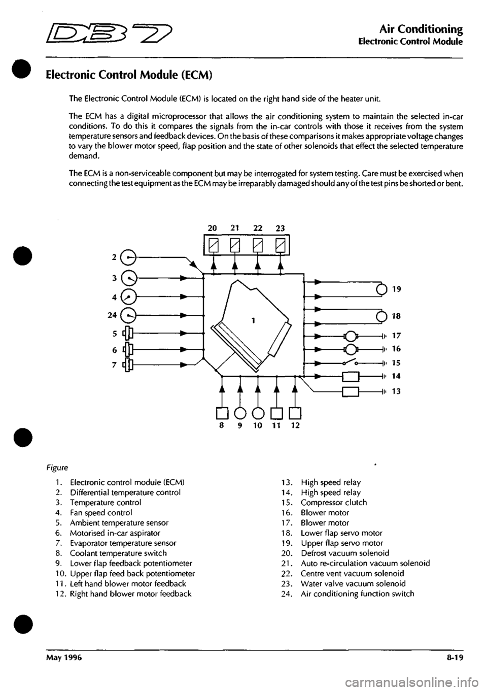
The Electronic Control Module (ECM) is located on the right hand side of the heater unit.
The ECM has a digital microprocessor that allows the air conditioning system to maintain the selected in-car
conditions. To do this it compares the signals from the in-car controls with those it receives from the system
temperature sensors and feedback
devices.
On the basis of these comparisons it makes appropriate voltage changes
to vary the blower motor
speed,
flap position and the state of other solenoids that effect the selected temperature
demand.
The ECM is a non-serviceable component but may be interrogated for system
testing.
Care must be exercised when
connecting
the test
equipment
as the ECM
may
be
irreparably
damaged
should any ofthe
test
pins
be
shorted or bent.
20 21 22 23
Q
A / A \/
Em
10 11
1.
Electronic control module (ECM)
2.
Differential temperature control
3. Temperature control
4.
Fan speed control
5. Ambient temperature sensor
6. Motorised in-car aspirator
7. Evaporator temperature sensor
8. Coolant temperature switch
9. Lower flap feedback potentiometer
10.
Upper flap feed back potentiometer
11.
Left hand blower motor feedback
12.
Right hand blower motor feedback
13.
High speed relay
14.
High speed relay
15.
Compressor clutch
16.
Blower motor
17.
Blower motor
18.
Lower flap servo motor
19.
LIpper flap servo motor
20.
Defrost vacuum solenoid
21.
Auto re-circulation vacuum solenoid
22.
Centre vent vacuum solenoid
23.
Water valve vacuum solenoid
24.
Air conditioning function switch
May 1996 8-19
Page 298 of 421
^n:m^^^
Air Conditioning
In Car Controls
In Car Controls
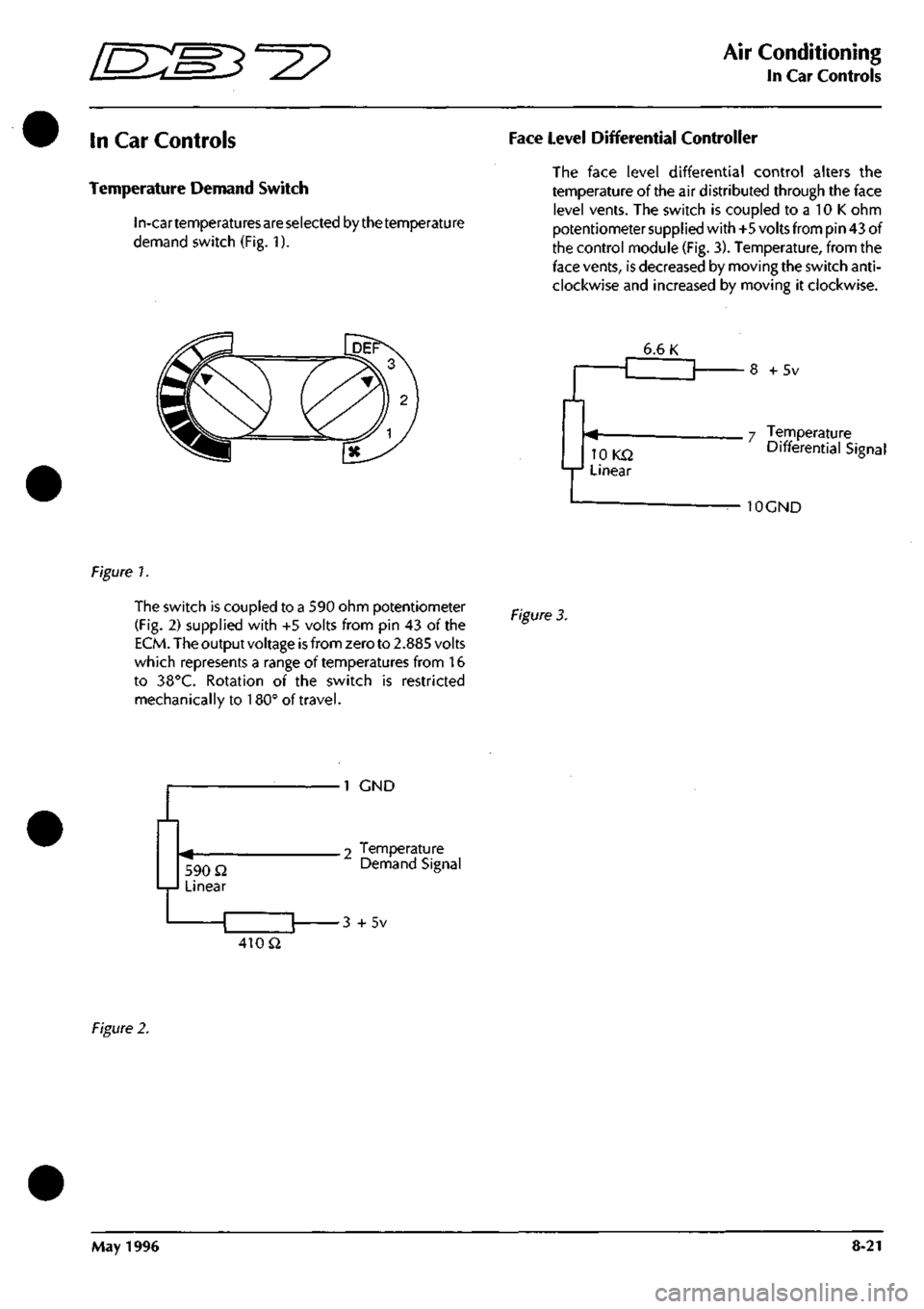
Temperature Demand Switch
In-cartemperatu
res are selected by
the temperature
demand switch (Fig. 1).
Face Level Differential Controller
The face level differential control alters the
temperature of the air distributed through the face
level vents. The switch is coupled to a 10 K ohm
potentiometersupplied with+5 volts
from
pin 43 of
the control module
(Fig.
3). Temperature, from the
face
vents,
is
decreased by moving the switch
anti
clockwise and increased by moving it clockwise.
6.6 K
lOKQ
Linear
+ 5v
7 Temperature
Differential Signal
10CND
Figure 1.
The switch is coupled to
a
590 ohm potentiometer
(Fig.
2) supplied with +5 volts from pin 43 of the
ECM.
The output voltage
is
from zero to
2.885
volts
which represents a range of temperatures from 16
to 38°C. Rotation of the switch is restricted
mechanically to 180° of travel.
Figure
3.
590 Q Linear
1 GND
.2 Temperature Demand Signal
•3 +5v
410 Q
Figure
2.
May 1996 8-21
Page 308 of 421
"3^2?
Air Conditioning
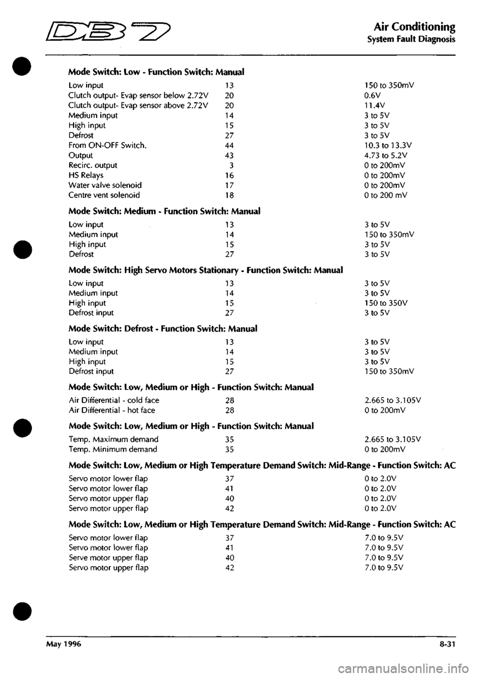
System Fault Diagnosis
Mode Switch: Low - Function Switch: Manual
Low input 13
Clutch output- Evap sensor below 2.72V 20
Clutch output- Evap sensor above 2.72V 20
Medium input 14
High input 15
Defrost 27
From ON-OFF Switch. 44
Output 43
Recirc. output 3
HS Relays 16
Water valve solenoid 17
Centre vent solenoid 18
Mode Switch: Medium - Function Switch: Manual
Low input
Medium input
High input
Defrost
13
14
15
27
Mode Switch: High Servo Motors Stationary - Function Switch: Manual
Low input 13
Medium input 14
High input 15
Defrost input 27
Mode Switch: Defrost - Function Switch: Manual
Low input
Medium input
High input
Defrost input
13
14
15
27
Mode Switch: Low, Medium or High - Function Switch: Manual
Air Differential - cold face 28
Air Differential - hot face 28
Mode Switch: Low, Medium or High - Function Switch: Manual
Temp.
Maximum demand 35
Temp.
Minimum demand 35
150 to 350mV
0.6V
11.4V
3to5V
3to5V
3to5V
10.3 to 13.3V
4.73 to 5.2V
0 to 200mV
0 to 200mV
0 to 200mV
0 to 200 mV
3to5V
150 to 350mV
3to5V
3to5V
3to5V
3to5V
150 to 350V
3to5V
3to5V
3to5V
3to5V
150 to 350mV
2.665 to 3.105V
0 to 200mV
2.665 to 3.105V
0 to 200mV
Mode Switch: Low, Medium or High Temperature Demand Switch: Mid-Range - Function Switch: AC
Servo motor lower flap 37 0 to 2.0V
Servo motor lower flap 41 0 to 2.0V
Servo motor upper flap 40 0 to 2.0V
Servo motor upper flap 42 0 to 2.0V
Mode Switch: Low, Medium or High Temperature Demand Switch: Mid-Range - Function Switch: AC
Servo motor lower flap 37 7.0 to 9.5V
Servo motor lower flap 41 7.0 to 9.5V
Serve motor upper flap 40 7.0 to 9.5V
Servo motor upper flap 42 7.0 to 9.5V
May 1996 8-31
Page 309 of 421
Air Conditioning
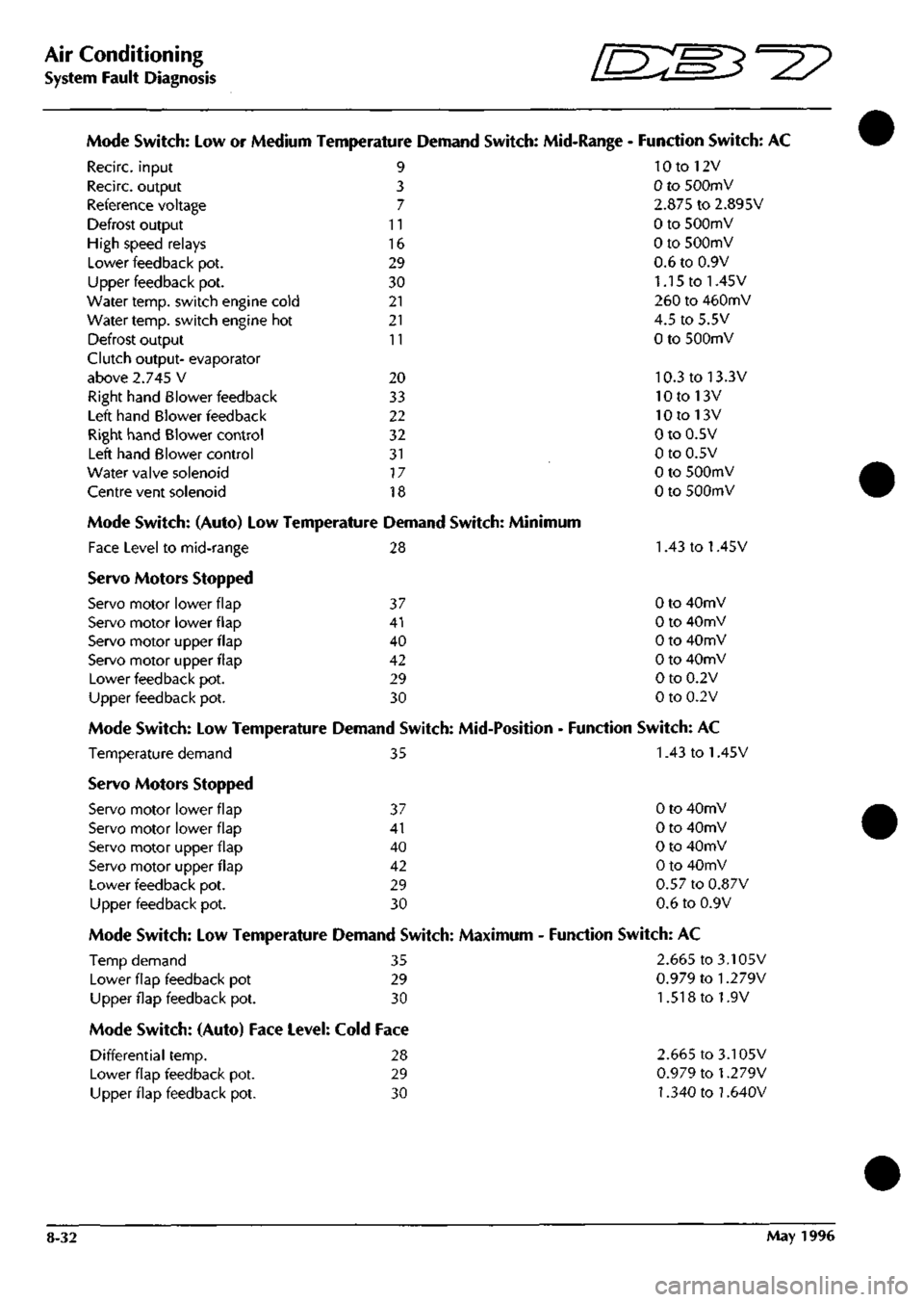
System Fault Diagnosis D^
Mode Switch: Low or Medium Temperature Demand Switch: Mid-Range - Function Switch: AC
10 to 12V
0 to SOOmV
2.875 to 2.895V
0 to 500mV
0 to 500mV
0.6 to 0.9V
1.15 to 1.45V
260 to 460mV
4.5 to 5.5V
0 to 500mV
10.3 to 13.3V
10 to 13V
10 to 13V
0 to 0.5V
0 to 0.5V
0 to 500mV
0 to SOOmV
Recirc. input
Recirc. output
Reference voltage
Defrost output
High speed relays
Lower feedback pot.
Upper feedback pot.
Water temp, switch engine cold
Water temp, switch engine hot
Defrost output
Clutch output- evaporator
above 2.745 V
Right hand Blower feedback
Left hand Blower feedback
Right hand Blower control
Left hand Blower control
Water valve solenoid
Centre vent solenoid
9
3
7
11
16
29
30
21
21
11
20
33
22
32
31
17
18
Mode Switch: (Auto) Low Temperature Demand Switch: Minimum
Face Level to mid-range 28 1.43 to 1.45V
Servo Motors Stopped
Servo motor lower flap 37 0 to 40mV
Servo motor lower flap 41 0 to 40mV
Servo motor upper flap 40 0 to 40mV
Servo motor upper flap 42 0 to 40mV
Lower feedback pot. 29 0 to 0.2V
Upper feedback pot. 30 0 to 0.2V
Mode Switch: Low Temperature Demand Switch: Mid-Position - Function Switch: AC
Temperature demand 35 1.43 to 1.45V
Servo Motors Stopped
Servo motor lower flap 37 0 to 40mV
Servo motor lower flap 41 0 to 40mV
Servo motor upper flap 40 0 to 40mV
Servo motor upper flap 42 0 to 40mV
Lower feedback pot. 29 0.57 to 0.87V
Upper feedback pot. 30 0.6 to 0.9V
Mode Switch: Low Temperature Demand Switch: Maximum - Function Switch: AC
Temp demand 35 2.665 to 3.105V
Lower flap feedback pot 29
Upper flap feedback pot. 30
0.979 to
1.279V
1.518 to 1.9V
Mode Switch: (Auto) Face Level: Cold Face
Differential temp. 28
Lower flap feedback pot. 29
Upper flap feedback pot. 30
2.665 to 3.105V
0.979 to
1.279V
1.340 to
1.640V
8-32 May 1996
Page 310 of 421
^7?
Air Conditioning
System Fault Diagnosis
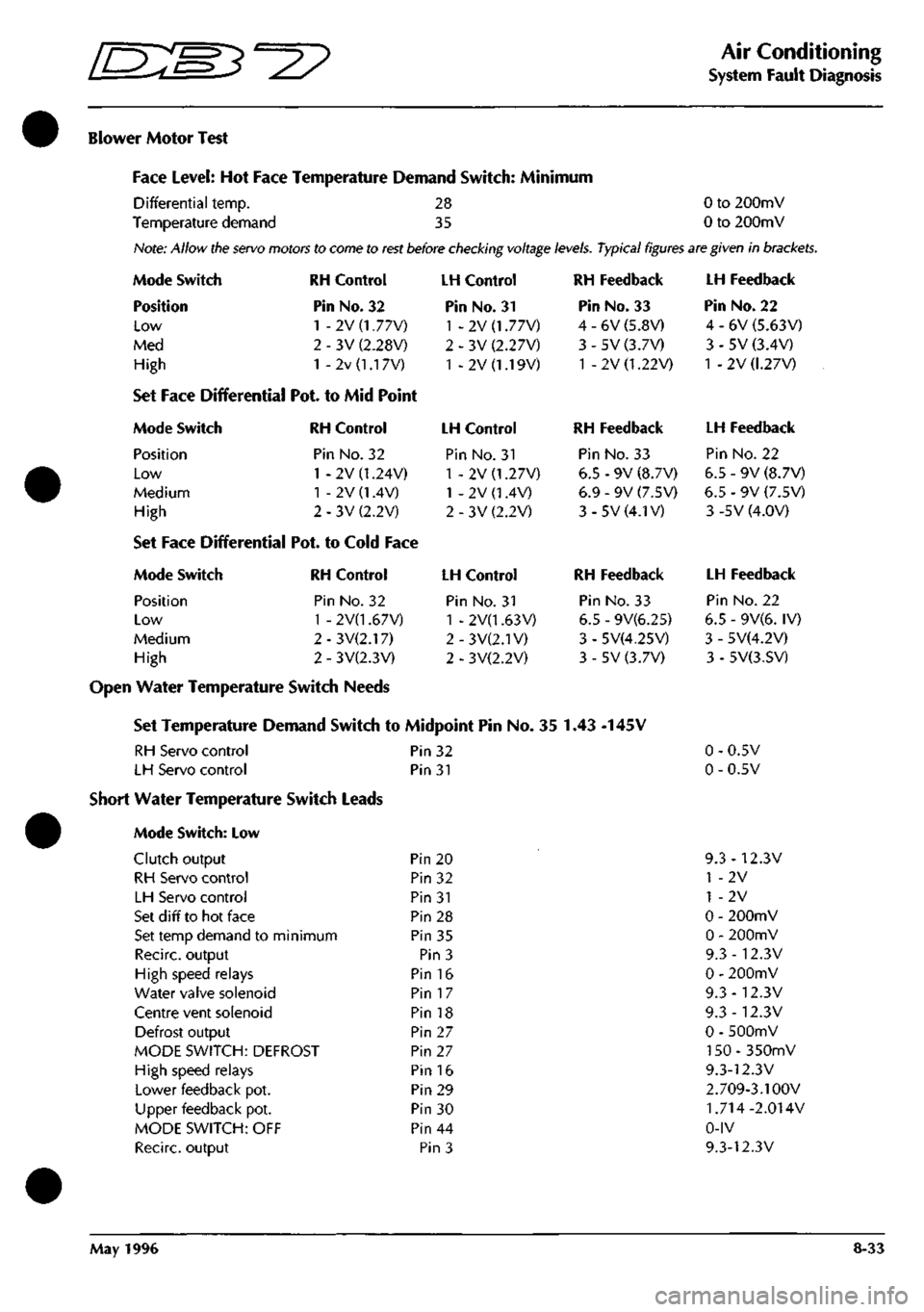
Blower Motor Test
Face Level: Hot Face Temperature Demand Switch: Minimum
Differential temp. 28 0 to 200mV
Temperature demand 35 0 to 200mV
Hote:
Allow
the servo motors
to
come to rest before checking voltage
levels.
Typical figures are given
in
brackets.
Mode Switch
Position
Low
Med
High
RH Control
Pin No. 32
1 - 2V (1.77V)
3V (2.28V)
2v
(1.1
7V)
Set Face Differential Pot. to Mid Point
Mode Switch RH Control
Position Pin No. 32
Low 1 - 2V (1.24V)
Medium 1 - 2V (1.4V)
High 2-3V(2.2V)
Set Face Differential Pot. to Cold Face
Mode Switch
Position
Low
Medium
High
RH Control
Pin No. 32
1 - 2V(1.67V)
2 - 3V(2.17)
2 - 3V(2.3V)
LH Control
Pin No. 31
1 -2V(1.77V)
2 - 3V (2.27V)
1 - 2V (1.19V)
LH Control
Pin No. 31
1 - 2V (1.27V)
1 - 2V (1.4V)
2 - 3V (2.2V)
LH Control
Pin No. 31
1 - 2V(1.63V)
2-3V(2.1V)
2 - 3V(2.2V)
RH Feedback
Pin No. 33
4 - 6V (5.8V)
3 - 5V (3.7V)
1 - 2V (1.22V)
RH Feedback
Pin No. 33
6.5 - 9V (8.7V)
6.9 - 9V (7.5V)
3-5V(4.1V)
RH Feedback
Pin No. 33
6.5 - 9V(6.25)
3 - 5V(4.25V)
3 - 5V (3.7V)
Open Water Temperature Switch Needs
Set Temperature Demand Switch to Midpoint Pin No. 35 1.43 -145V
RH Servo control Pin 32
LH Servo control Pin 31
Short Water Temperature Switch Leads
Mode Switch: Low
Clutch output
RH Servo control
LH Servo control
Set d iff to hot face
Set temp demand to minimum
Recirc. output
High speed relays
Water valve solenoid
Centre vent solenoid
Defrost output
MODE SWITCH: DEFROST
High speed relays
Lower feedback pot.
Upper feedback pot.
MODE SWITCH: OFF
Recirc. output
Pin 20
Pin 32
Pin 31
Pin 28
Pin 35
Pin 3
Pin 16
Pin 17
Pin 18
Pin 27
Pin 27
Pin 16
Pin 29
Pin 30
Pin 44
Pin 3
LH Feedback
Pin No. 22
4 - 6V (5.63V)
3 - 5V (3.4V)
1 -2V (1.27V)
LH Feedback
Pin No. 22
6.5 - 9V (8.7V)
6.5 - 9V (7.5V)
3 -5V (4.0V)
LH Feedback
Pin No. 22
6.5 - 9V(6. IV)
3 - 5V(4.2V)
3 - 5V(3.SV)
0.5V
0.5V
9.3-12.3V
1 -2V
1 -2V
0 - 200mV
0 - 200mV
9.3-12.3V
0 - 200mV
9.3-12.3V
9.3-12.3V
0 - 500mV
150-350mV
9.3-12.3V
2.709-3.1 OOV
1.714-2.014V
0-IV
9.3-12.3V
May 1996 8-33
Page 314 of 421
^?
Air Conditioning
Sanden Compressor SD7H15
Sanden Compressor SD7H15
The Sanden SD7H15 compressor
is a 7
cylinder
machine with
a
bore
of
29.3
mm (1.15 in) and a
stroke
of
32.8
mm (1.29
inches).
The displacement
per
revolution
is
155cc
(9.5
cubic inches).
The magnetic clutch
is
engineered with
the
compressor
as a
complete assembly resulting
in a
relatively small unit
of
lightweight construction.
The compressor may be mounted up to 90° from
its
upright position.
The compressor incorporates
a
lubrication system
which reduces the
oil
circulation ratio
to a
level
of
less than
2% at 1800 rpm.
An
oil
deflector
and
positive pressure differential
lubrication system promotes oiling
to the
cylinder
wall,
piston
rod
assemblies, main bearings
and
shaft
seal,
and
ensures that
oil
circulation
to the
refrigeration circuit
is
kept
to a
minimum.
The
compressor ischarged
with!
35 cc(4.6fluid ounces)
ofSunico NoSGSoil at the factory. Only this oil
or
oneoftheequivalentoilsdetailed below should
be
used.
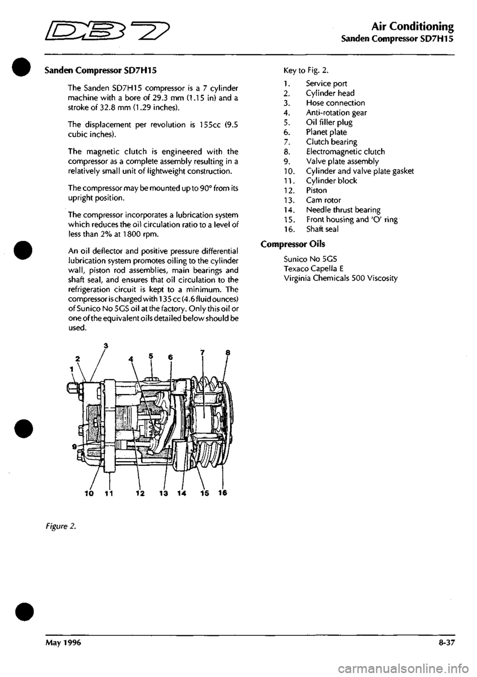
Key
1.
2.
3.
4.
5.
6.
7.
8.
9.
10.
11.
12.
13.
14.
15.
16.
to Fig. 2.
Service port
Cylinder head
Hose connection
Anti-rotation gear
Oil filler plug
Planet plate
Clutch bearing
Electromagnetic clutch
Valve plate assembly
Cylinder and valve plate gasket
Cylinder block
Piston
Cam rotor
Needle thrust bearing
Front housing and 'O' ring
Shaft seal
Compressor Oils
Suni
CO
No 5GS
Texaco Capella E
Virginia Chemicals 500 Viscosity
13
14 15 16
Figure
2.
May
1996
8-37