door ASTON MARTIN DB7 1997 User Guide
[x] Cancel search | Manufacturer: ASTON MARTIN, Model Year: 1997, Model line: DB7, Model: ASTON MARTIN DB7 1997Pages: 421, PDF Size: 9.31 MB
Page 108 of 421
^7
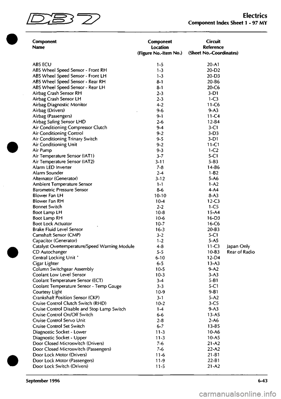
Electrics
Component Index Sheet 1-97 MY
Component
Name
ABS ECU
ABS Wheel Speed Sensor - Front RH
ABS Wheel Speed Sensor - Front LH
ABS Wheel Speed Sensor - Rear RH
ABS Wheel Speed Sensor - Rear LH
Airbag Crash Sensor RH
Airbag Crash Sensor LH
Airbag Diagnostic Monitor
Airbag (Drivers)
Airbag (Passengers)
Airbag Safing Sensor LHD
Air Conditioning Compressor Clutch
Air Conditioning Control
Air Conditioning Trinary Switch
Air Conditioning Unit
Air Pump
Air Temperature Sensor (IAT1)
Air Temperature Sensor (IAT2)
Alarm LED Inverter
Alarm Sounder
Alternator (Generator)
Ambient Temperature Sensor
Barometric Pressure Sensor
Blower Fan LH
Blower Fan RH
Bonnet Switch
Boot Lamp LH
Boot Lamp RH
Boot Lock Actuator
Brake Fluid Level Sensor
Camshaft Sensor (CMP)
Capacitor (Generator)
Catalyst Overtemperature/Speed Warning Module
CD Autochanger
Central Locking Unit '
Cigar Lighter
Column Switchgear Assembly
Coolant Low Level Sensor
Coolant Temperature Sensor (ECT)
Coolant Temperature Sensor - Temp Gauge
Courtesy Light
Crankshaft Position Sensor (CKP)
Cruise Control Clutch Switch (RHD)
Cruise Control Disable and Stop Lamp Switch
Cruise Control On/Off Switch
Cruise Control Servo Unit
Cruise Control Set Switch
Diagnostic Socket - Lower
Diagnostic Socket - Upper
Door Closed Microswitch (Drivers)
Door Closed Microswitch (Passengers)
Door Lock Motor (Drivers)
Door Lock Motor (Passengers)
Door Lock Switch (Drivers)
Component
Location
(Figure No.-ltem No.)
1-5
1-3
1-3
8-1
8-1
2-3
2-3
4-2
9-6
9-1
2-6
9-4
9-2
9-5
9-2
9-3
3-7
3-11
7-8
2-4
3-12
1-1
8-6
10-10
10-4
2-2
10-8
10-6
10-7
16-3
3-2
1-2
4-8
5-5
6-10
6-5
10-5
10-3
3-4
3-3
10-9
3-1
10-2
1-4
6-6
2-8
6-7
11-3
11-3
7-6
7-6
11-6
11-9
11-5
Circuit
Reference
(Sheet No.-Coordinates)
20-A1
20-D2
20-D3
20-B6
20-C6
3-D1
1-C3
11-C6
9-A3
11-C4
12-B4
3-C1
3-D3
3-D1
11-CI
1-C2
5-C1
5-B3
14-B6
1-B2
5-A6
1-A2
4-A4
8-A3
12-C3
1-C5
15-A4
16-D3
16-C6
20-B3
5-C1
5-A5
11-C3 Japan Only
10-B3 Rear of Radio
12-D4
13-A3
9-A2
3-A3
5-B1
5-C1
9-B1
5-A2
3-C5
9-A3
13-A5
2-A6
13-B5
10-A6
10-A5
21-A2
22-A2
21-B1
22-Bl
21-A2
September 1996 6-43
Page 109 of 421
Electrics
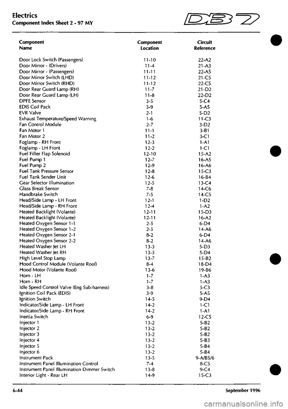
Component Index Sheet 2 - 97 MY
Component
Name
Door Lock Switch (Passengers)
Door Mirror - (Drivers)
Door Mirror - (Passengers)
Door Mirror Switch (LHD)
Door Mirror Switch (RHD)
Door Rear Guard Lamp (RH)
Door Rear Guard Lamp (LH)
DPFE Sensor
EDIS Coil Pack
EVR Valve
Exhaust Temperature/Speed Warning
Fan Control Module
Fan Motor 1
Fan Motor 2
Foglamp - RH Front
Foglamp - LH Front
Fuel Filler Flap Solenoid
Fuel Pump 1
Fuel Pump 2
Fuel Tank Pressure Sensor
Fuel Tank Sender Unit
Gear Selector Illumination
Glass Break Sensor
Handbrake Switch
Head/Side Lamp - LH Front
Head/Side Lamp - RH Front
Heated Backlight (Volante)
Heated Backlight (Voiante)
Heated Oxygen Sensor
1
-1
Heated Oxygen Sensor
1
-2
Heated Oxygen Sensor 2-1
Heated Oxygen Sensor 2-2
Heated Washer Jet LH
Heated Washer Jet RH
High Level Stop Lamp
Hood Control Module (Volante Roof)
Hood Motor (Volante Roof)
Horn - LH
Horn - RH
Idle Speed Control Valve (Eng Sub-harness)
Ignition Coil Pack (EDIS)
Ignition Switch
Indicator/Side Lamp - LH Front
Indicator/Side Lamp - RH Front
Inertia Switch
Injector 1
Injector 2
Injector 3
Injector 4
Injector 5
Injector 6
Instrument Pack
Instrument Panel Illumination Control
Instrument Panel Illumination Dimmer Switch
Interior Light - Rear LH
6-44
Component
Location
11-10
n-4
11-11
11-12
11-12
11-7
11-8
3-5
3-9
2-1
1-6
2-7
11-1
11-2
12-3
12-2
12-10
12-7
12-9
12-8
12-6
12-5
7-8
7-5
12-1
12-4
12-11
12-11
2-5
2-5
8-2
8-2
13-3
13-3
13-7
8-4
13-6
1-7
1-7
3-8
3-9
14-5
14-2
14-2
6-9
13-2
13-2
13-2
13-2
13-2
13-2
13-5
7-4
13-8
14-9
fEB^-^?
Circuit
Reference
22-A2
21-A3
22-A5
21-C5
22-C5
21-D2
22-D2
5-C4
5-A5
5-D2
11-C3
3-D2
3-B1
3-C1
1-A1
1-C1
15-A2
16-A5
16-A6
15-C3
16-B4
13-C4
14-C6
14-C5
1-D2
1-A2
15-D3
16-A2
6-D4
14-A6
6-D4
14-A6
5-D3
5-D4
15-82
18-D4
19-B6
1-A3
1-A3
5-C3
5-A5
9-D4
1-C1
1-A1
12-C5
5-B2
5-B2
5-B2
5-B3
5-B4
5-B4
9-A/B5/6
8-C5
9-C4
15-C3
September 1996
Page 111 of 421
Electrics
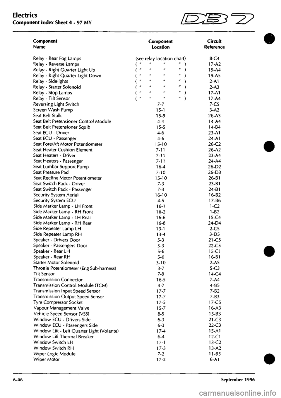
Component Index Sheet 4-97 MY ^7
Component
Name
Relay - Rear Fog Lamps
Relay - Reverse Lamps
Relay - Right Quarter Light Up
Relay - Right Quarter Light Down
Relay - Sidelights {
Relay - Starter Solenoid
Relay - Stop Lamps
Relay- Tilt Sensor
Reversing Light Switch
Screen Wash Pump
Seat Belt Stalk
Seat Belt Pretensioner Control Module
Seat Belt Pretensioner Squib
Seat ECU - Driver
Seat ECU - Passenger
Seat Fore/Aft Motor Potentiometer
Seat Heater Cushion Element
Seat Heaters - Driver
Seat Heaters - Passenger
Seat Lumbar Support Pump
Seat Pressure Pad
Seat Recline Motor Potentiometer
Seat Switch Pack - Driver
Seat Switch Pack - Passenger
Security System Aerial
Security System ECU
Side Marker Lamp - LH Front
Side Marker Lamp - RH Front
Side Marker Lamp - LH Rear
Side Marker Lamp - RH Rear
Side Repeater Lamp LH
Side Repeater Lamp RH
Speaker - Drivers Door
Speaker - Passengers Door
Speaker - Rear LH
Speaker - Rear RH
Starter Motor Solenoid
Throttle Potentiometer (Eng Sub-harness)
Tilt Sensor
Transmission Connector
Transmission Control Module (TCM)
Transmission Input Speed Sensor
Transmission Output Speed Sensor
Tyre Compressor Socket
Vapour Management Valve
Vehicle Speed Sensor (VSS)
Window ECU - Drivers Side
Window ECU - Passengers Side
Window Lift - Left Quarter Light (Volante)
Window Lift Thermal Breaker
Window Switch LH
Window Switch RH
Wiper Logic Module
Wiper Motor
6-46
Component
Location
Circuit
Reference
(see relay location chart) 8-C4 it ti It
II H U
tl 11 U
a II 11
II II II
II Ji II
II II II
7-7
15-1
15-9
4-4
15-5
4-6
4-6
15-10
7-11
7-n
7-11
16-4
7-10
15-10
7-3
7-3
16-10
4-5
16-1
16-2
16-6
16-8
13-1
13-4
5-3
5-3
5-6
5-6
3-10
3-7
7-9
16-5
4-7
17-7
17-7
17-5
15-7
8-5
6-3
6-3
17-4
6-4
17-1
17-3
7-2
17-2
' ) 17-A2
' ) 19-A4
' ) 19-A5
' ) 2-A1
' ) 2-A3
' ) 17-A1
' ) 17-A4
7-C5
3-A2
26-A3
14-A4
14-B4
23-A1
24-A1
26-C2
26-A2
23-A4
24-A4
26-D2
26-D3
26-B1
23-B1
24-B1
16-B2
17-B6
1-C2
1-82
15-C4
24-D4
2-C5
3-D5
21-C5
22-C5
15-Cl
16-B1
2-A5
5-C3
14-C4
7-A4
4-B5
7-B2
7-B3
17-C5
16-A3
15-B3
21-C3
22-C3
15-A1
12-Cl
13-C2
13-A2
11-B5
6-A1
September 1996
Page 129 of 421
Electrics
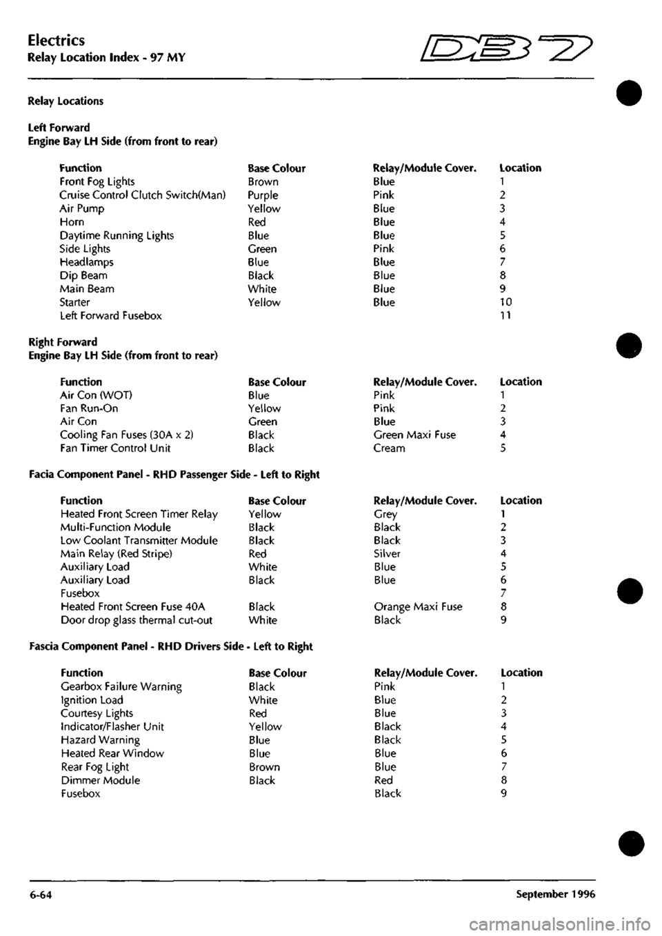
Relay Location Index - 97 MY 5^^?
Relay Locations
Left Forward
Engine Bay LH Side (from front to
Function
Front Fog Lights
rear)
Cruise Control Clutch Switch(Man)
Air Pump
Horn
Daytime Running Lights
Side Lights
Headlamps
Dip Beam
Main Beam
Starter
Left Forward Fusebox
Base Colour
Brown
Purple
Yellow
Red
Blue
Green
Blue
Black
White
Yellow
Relay/Module Cover.
Blue
Pink
Blue
Blue
Blue
Pink
Blue
Blue
Blue
Blue
Location
1
2
3
4
5
6
7
8
9
10
11
Right Forward
Engine Bay LH Side (from front to rear)
Function Base Colour
Air Con (WOT) Blue
Fan Run-On Yellow
Air Con Green
Cooling Fan Fuses (30A x 2) Black
Fan Timer Control Unit Black
Facia Component Panel - RHD Passenger Side - Left to Right
Function Base Colour
Heated Front Screen Timer Relay Yellow
Multi-Function Module Black
Low Coolant Transmitter Module Black
Main Relay (Red Stripe) Red
Auxiliary Load White
Auxiliary Load Black
Fusebox
Heated Front Screen Fuse 40A Black
Door drop glass thermal cut-out White
Fascia Component Panel - RHD Drivers Side - Left to Right
Function
Gearbox Failure Warning
Ignition Load
Courtesy Lights
Indicator/Flasher Unit
Hazard Warning
Heated Rear Window
Rear Fog Light
Dimmer Module
Fusebox
Base Colour
Black
White
Red
Yellow
Blue
Blue
Brown
Black
Relay/Module
Pink
Pink
Blue
Cover.
Green Maxi Fuse
Cream
Relay/Module
Grey
Black
Black
Silver
Blue
Blue
Cover.
Orange Maxi Fuse
Black
Relay/Module
Pink
Blue
Blue
Black
Black
Blue
Blue
Red
Black
Cover.
Location
1
2
3
4
5
Location
1
2
3
4
5
6
7
8
9
Location
1
2
3
4
5
6
7
8
9
6-64 September 1996
Page 131 of 421
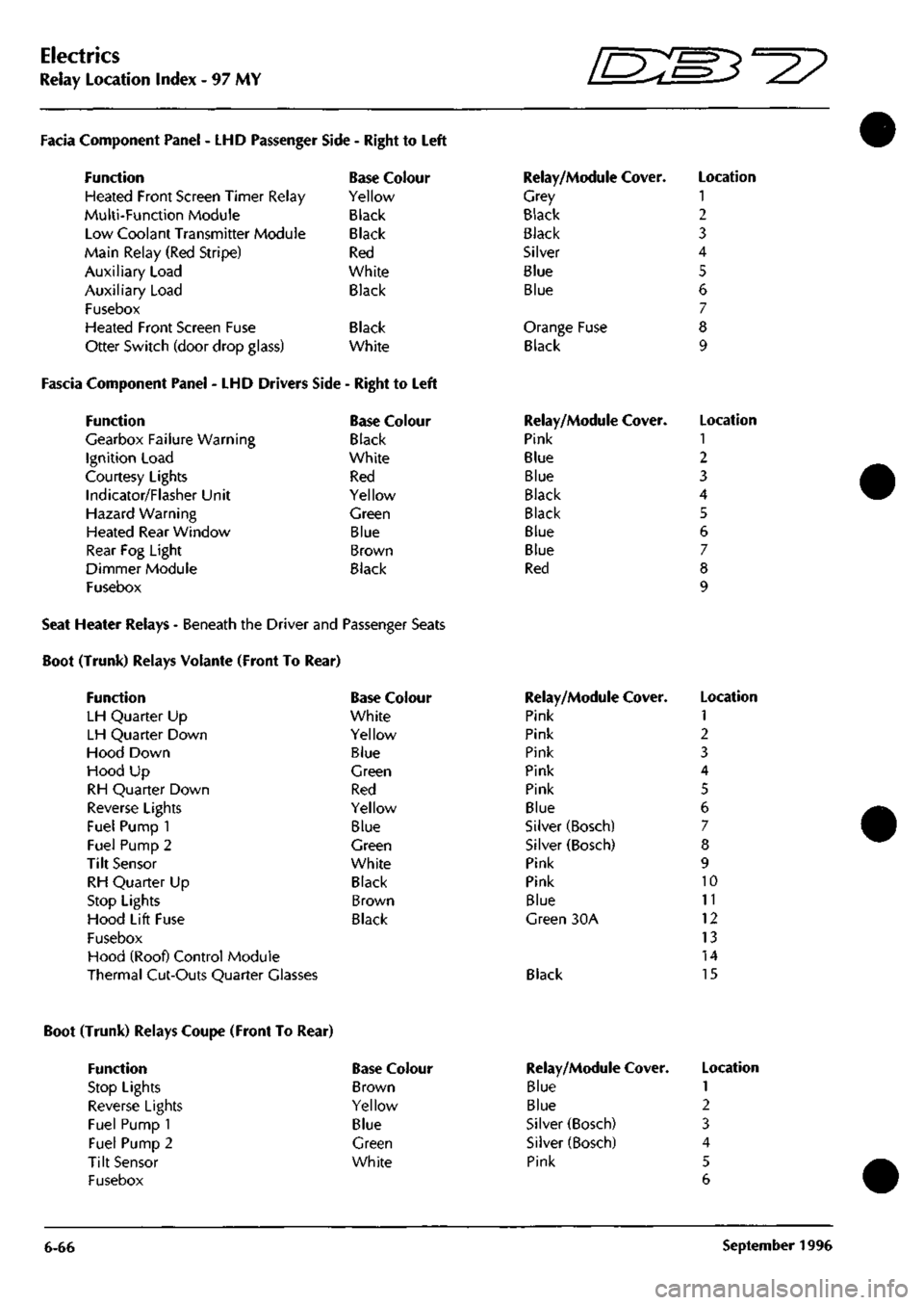
Electrics
Relay Location Index - 97 MY
D^^
Facia Component Panel
- LHD
Passenger
Function
Heated Front Screen Timer Relay
Multi-Function Module
Low Coolant Transmitter Module
Main Relay (Red Stripe)
Auxiliary Load
Auxiliary Load
Fusebox
Heated Front Screen Fuse
Otter Switch (door drop glass)
Side
-
Right
to
Left
Base Colour
Yellow
Black
Black
Red
White
Black
Black
White
Fascia Component Panel
- LHD
Drivers Side
-
Right
to
Left
Function
Gearbox Failure Warning
Ignition Load
Courtesy Lights
Indicator/Flasher Unit
Hazard Warning
Heated Rear Window
Rear
Fog
Light
Dimmer Module
Fusebox
Base Colour
Black
White
Red
Yellow
Green
Blue
Brown
Black
Relay/Module Cover.
Grey
Black
Black
Silver
Blue
Blue
Orange Fuse
Black
Relay/Module Cover.
Pink
Blue
Blue
Black
Black
Blue
Blue
Red
Location
1
2
3
4
5
6
7
8
9
Location
1
2
3
4
5
6
7
8
9
Seat Heater Relays - Beneath the Driver and Passenger Seats
Boot (Trunk) Relays Volante (Front To Rear)
Function
LH Quarter
Up
LH Quarter Down
Hood Down
Hood
Up
RH Quarter Down
Reverse Lights
Fuel Pump
1
Fuel Pump
2
Tilt Sensor
RH Quarter
Up
Stop Lights
Hood Lift Fuse
Fusebox
Hood (Roof) Control Module
Thermal Cut-Outs Quarter Glasses
Base Colour
White
Yellow
Blue
Green
Red
Yellow
Blue
Green
White
Black
Brown
Black
Relay/Module Cover.
Pink
Pink
Pink
Pink
Pink
Blue
Silver (Bosch)
Silver (Bosch)
Pink
Pink
Blue
Green
30A
Black
Location
1
2
3
4
5
6
7
8
9
10
11
12
13
14
15
Boot (Trunk) Relays Coupe (Front To Rear)
Function
Stop Lights
Reverse Lights
Fuel Pump 1
Fuel Pump 2
Tilt Sensor
Fusebox
Base Colour
Brown
Yellow
Blue
Green
White
6-66
Relay/Module
Blue
Blue
Silver (Bosch)
Silver (Bosch)
Pink
Cover. Location
1
2
3
4
5
6
September
1996
Page 156 of 421
in
NO COLOUF 711 UW
842 KB
836 8G
924 UIN
923 RIN
710 B 769 KB 709 W
925 N
712 OB 709 B
920 W
PIN 1 ? 3 4 5 6 1 8 9 1(1 II 1? 13 14 15 16 17 IS 19 20
ARE*
9.02
11X3
II.C3
I2.A3
I2.A3
9.02 10.01 9.02
II.B4-I23
9.02 I2.CI-I3I
I2.C2-I36
NO COLOUI 297 NS 294 R 304 YB 238 OK 325 WS 264 OS 268 NB 326 UIN 327 RIN 328 UG 13 RO 330 LGO 135 OY 54 C 333 P 334 KB 155 KB 290 KB 335 OB 336 0 337 RN 338 OY 339 m 340 OG
PIN 1 2 3 4 5 6 / 8 9 10 II 12 13 14 15 16 {I 18 19 20 21 22 23 24
AREA II.A3 10.04 10.04 9.A4 9.A4 9.A4 9.A4 I0.C5 I0.C5 9.A6 B.BI 10.04 B.BI B.BI ILB4-I22 I2.C2-I3; ii.a-lil 12.C2-I3; 10.04 10.04 10.04 10.01 II.Al lo.n
• SHEET 6 • AREA B/C2
D
• 0 0
a
D
DOd-,
0 D
1—
D D
n:
a a *— D • • D
o[nr 0 0 • G
a
•
•••npaa
ENGINE HARNESS
SHEET 6 AREA C4
NO COLOUf 341 BRD 926 BRD 186 BY 187 BU 189 SP 344 RIN 923 RIN 345 8G 346 UIN 924 UIN 194 YG 198 RN 348 YU 927 LGO 809 YH 316 B
PIN 1 I •/ 3 4 5 5 6 7 7 8 9 10 II 1? 13
AREA 12.82-132 10.83-112 II.BI II.BI II.BI 10.A4 I2.AI I0.B5-I06 I0.A4 I2.BI II.CI II.CI I0.A4 I0.B2-97 10.04 I0.A4
RED FOWARD 12 I
^
SHEET 3 AREA B6
NO COLOUf ISO
181
138 178 149
163
145
147
GW
NS
YR BK WR
GN
LGB
BS
PIN 1 2 3 4 5 6 1 8 9 10 II 12 13 14 15 16 17 18 19 20
AREA 10.82-91
11.Al
8.BI I2.C2-I4C I2.B2
CI.CI
11.86
M.B2-II6
NO COLOUf 932 B 933 BR 934 BS 935 W 936 NR
937 P 623 BC 938 BS 939 BY 715 PO 940 BP 854 WB 808 K 839 W>
941 BU 743 GO 942 BW 838 PS
PIN 1 ? 3 4 5 6 7 8 9 10 H 1? 13 14 15 16 17 18 19 20
AREA 12.03-143 I0.B2-96 I2C3-I46 I2.C2-I36
8.B5-70
I2.C2-I39 8.C4 II.B2-II6
9.A5-88
9.03
8.C2-60
11.03 10.04 1I.C3
II.B5-I27 9.Ae IO.B2-94 II.C3
AiR8&G SENSOR
MULTIFUNCTION MODULE
ir='fn)—II,
NO COLOUR PIN 866 ON I 873
KU
2 3 863 OP 4 II.C6
AREA II.C6 II.C6
DOOR HAflNESS SHEET 22 ;^ 1>. AREA B6 "^ *^ NO COLOUf 981 99? 983 984
986 987 988 989 818 819 381 38? 383
990 991 99? 99.1 994
OG OU OW OR
6 BW PG PW RG GR YG YU Y
LG NU BS RN B
PIN 1 2 3 4 5 6 7 8 9 10 11 12 13 14 15 16 If 18 19 20 21 22
AREA I2.C4-I4S 12.C3-I4S l2.C4-l4t 12.C3-I47
I2.C2-I37 I2.C3-I4I
8.82-61
8.83-65
I2.C2-I34 11.01 8.01 8.01 8.DI
8.B5-69
I2.C2-135 I2.C3-I46 IO.B5-I07 I2.C3-I42
NO COLOUt 891 NK
995 RW 996 PN
909 NG 997 BS 998 WK 904 OW 750 OS 749 OU 999 BK
PIN 1 2 3 4 5 6 7 8 9 10 11 1? 13 14 15 16
AREA
11.
Al
II.B2-1I4 11.82-113
ILA3 I2.C3-I46 II.B3-II7 II.AI 9.A6 9.A6 I2.C2-I40
LOAD RELAY NO COLOUR 94 7 B 948 W 949 W
950
N
PIN 85 86 87 87A 30
AREA I2.C2-I4;
e.B6-74
I2.C1-I29
II.A5-I25
AUX LOAD RELAY NO COLOUB 951 B 952
WK
953
WK
954
N
PIN 8.5 86 87 87A 30
AREA I2.C3-I42 II.B5-I17 11.85-128
II.B4-123
NO COLOUB 955 8 956
WR
957
KB
958
KB
899 NP
PIN 85 86 87 87A 30
AREA
B.B4-67
12.C2-I38 12.C2-I33 10.84-104 II.AI
HO COLOUR 959
BK
960 W 889 N 961 NY
PIN 85 86 8/ 30
AREA 10.85-10! I2.CI-I29 II.A6 I2.C3-I44
NO COLOUE 972 OG 973 OW 974 P 975 BK 976 W 977 OR 978 OU
PIN 1 2 3 4 5 6 7 8 9 10 II 12 13 14
AREA I2.C4-I49 l2.C4-l4t I2.C2-I39 I2.C2-I40 I2.C2-I36 I2.C3-I47 12.C3-145
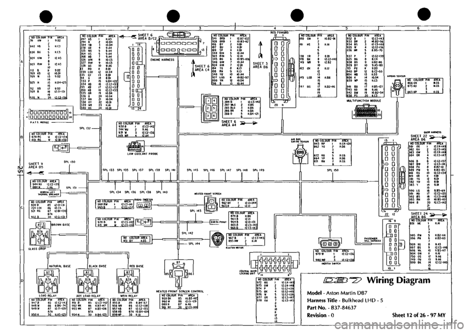
Wiring Diagram
Model - Aston Martin DB7
Harness Title - Bulkhead LHD
Part No. - B3
7-8463
7
Revision - 0 Sheet 12 of 26-97 MY
Page 174 of 421

NO COLOUR PIN AREA 1233 BP I 2LC4-2I3 1234 8 2 2I,A4-2I2 3
MICRO SWITCH NO COLOUR PIN AREA 371 OU I 2I.B6 373 OR 2 2I.B6 1235 B 3 2I.B5-209 LOCK SWITCH
NO COLOUR 1241 B 1242 RN 1243 1 1244 Y6 1245 YU
PIN 1 ? 3 4 5
AREA 2I.A4-2I2 2I.B4-2II 2I.B5-205 2I.C5-206 2LB5-207
NO COLOUR PIN 372 OW I 370
OG
2
AREA 2I.B6 2I.B6
LOCK MOTOR [am
L.H DOOR MIRROR NO COLOUR PIN 1236 B 1 1237 RM 2 1238 Y 3 1239 YR 4 1240 YB 5
AREA 2I,A4-2I2 2LB4-2II 21.85-205 2I.C5-20B 2LB4-2IO i0©j R.H OOOR MIRROR
NO COLOUR AREA 1246 B 2I.A4-2I2 1247 B 21.85-209
X
WINDOW ECU
(am
(-
("
1 13 • • Q 0 D D DOZ^ D D D D D D
• D DOZ D Q D 0 G 0
NO COLOUR PIN 966 8 I 967
BW
2
AREA 21.86 2I.B6
REAR GUARD LAMP
NO COLOUR PIN AREA 385 LG 1249 BP 379 R
380
G
1248
8
386
NU
A B C D E F 6
2I.C6 2LC4-2I3 2I.B6 2I.B6
2I.B5-209 2I.C6
DOOR MIRROR SWITCH
NO
COLOUR
1250
YR
1251
YG
1252
Y
1253
LG
1254
YU
1230
8
1255
YB
PIN 1 ? 3 4 5 6
7 8
AREA 21.05-209 2I.C5-206 2LB5-205 2I.C6 2LA4-207 2L85-2I2 21,04-210
NO
COLOUf
370
00
371
OU
372
OW
373
OR
375
8
376
BW
377
PG
376
PW
379
R
380
G
381
YG
362
YU
383
Y
1230
LG
385
LG
386
NU
387
BP
388
RN
389
8
1231
YR
1232
YB
PIN 1 2 i
4 5 6
7 8 9 10 II 12 13 14 15 16 17 IB 19 20 71 22
AREA
21.81
2I.A2
21.81
2I.BI
2I.A2 2I.C5 2I.D2
21.02
2I.D2
21.03
21.03-206 2I.C5-207 2I.B5-205 2I.D5 2I.D3 2I.D3 2LC4-2I3 2I.C4-2II 21,85-209 2I.C5-208 2I.C4-2I0
SHEET 8 AREA Dl
NO COLOUR PIN 377P 1 378 PW 2 3
AREA 21.86 21.86 Wiring Diagram
Model - Aston Martin DB7
Harness Title - Drivers Door
Part No. - B3
7-84646
Revision - 0 Sheet 21 of 26-97 MY
Page 176 of 421

NO COLOUR
PIN
ARE*
1222
BP I
22.CA-Z0A
1223 B 2 22*4-203 3
MICRO SWITCH
KO COLOUR
PIN
ARE* 9S2
OU I
22.B6
984
OR 2
22.B6 1224
B 3
22.B5-200 LOCK SWITCH
NO COLOUR 1207
6
1208
RN 1209 t 1210 TG 1211 YU
PIN 1 ? 3 4 5
AREA 22.A4-203 22.B4-202 22.85-196 22.C5-I97 22.85-198
NO COLOUR PIN AREA 391 OW I 22.B6 389
OG
2 22.86
in LOCK MOTOR g] [J
L.H DC NO COLOUR
1225
B
1226
RN
1227
Y
1228
YR 1229 YB
PIN 1 2 3 4 5
OR MIRROR AREA 22.A4-203 22.B4-202 22.85-196 22.C5-I99 22.84-201
R.H DOOR MIRROR
NO COLOUR AREA
1212
B
22.A4-203
1213 B 22.85-200
SHEET 12 ^2> C=. AREA C6 ^* 1**^
SPL 200 SPL 198
n n 'I "TT
SPL
201
SPL 199
¥mpD'
c
1"
1 13
D
D
D
a D 0 00=1 D 0 0 0 Q 0 Q Q DDC D 0 D 0 D 0
NO COLOUF 981
06
982
OU
983
OW
984
OR
986
B
987
BW
988
PO
989
PW
818
RG
819
CR
381
YG
382
YU
383
Y
1206
LC
990
LO
991
NU
992
8P
993
RN
994
B
1204
YR
1205
YB
PIN 1 2 3
4 5 6
1 8 9 10 II 12 13 14 15 16 17 18 19 20 21 22
AREA 22.BI 22.A2 22.BI 22.A2
22.C5 22.C5 22.02 22.02 22.03 22.03 22.C5-197 22.B5-I98 22.B5-I96 22.D3 22.D3 22.03 22.C4-204 22.C4-202 22.B5-200 22.C5-I99 22.C4-20I
NO COLOUR
PIN
AREA
986 8 I 22.B6 987
BW
2
22.B6
WINDOW ECU
REAR GUARD LAMP
NO COLOUR PIN 990 LG A
1221
BP B
818
R C
819
G D
220
B
991
NU
AREA 22.C6 22.C4-204 22.86 22.B6
22.B5-200 22.C6
DOOR MIRROR SWITCH
NO
1214 1215 1216 1217 1218
1206 1219
COLOUR YR YG Y LG YU B YB
PIN 1 ? 3 4 5 6 7 8
AREA 22.C5-I99 22.C5-I97 22.85-196 22.C6 22.A4-I98 22.B5-203 22.C4-20I
NO COLOUR PIN AREA 988 PG I 22.B6 989 PW 2 22.B6 3
[D:[B3-=2? Wiring Diagram
Model - Aston Martin DB7
Harness Title - Passengers Door
Part No. - B37-84647
Revision - 0 Sheet 22 of 26 - 97 MY
Page 188 of 421
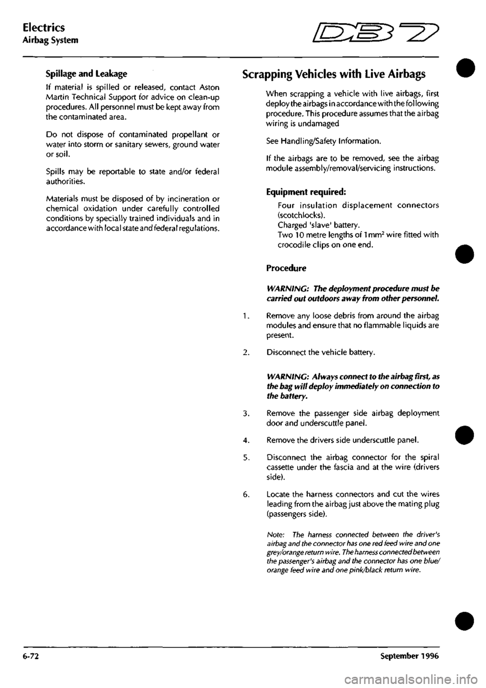
Electrics
Airbag System =7?
Spillage and Leakage
If material is spilled or released, contact Aston
Martin Technical Support for advice on clean-up
procedures. All personnel must be kept away from
the contaminated area.
Do not dispose of contaminated propellant or
water into storm or sanitary sewers, ground water
or
soil.
Spills may be reportable to state and/or federal
authorities.
Materials must be disposed of by incineration or
chemical oxidation under carefully controlled
conditions by specially trained individuals and in
accordancewith local stateandfederal regulations.
Scrapping Vehicles with Live Airbags
when scrapping a vehicle with live airbags, first
deploy the airbags in accordance with the following
procedure. This procedure assumes that the airbag
wiring is undamaged
See Handling/Safety Information.
If the airbags are to be removed, see the airbag
module assembly/removal/servicing instructions.
Equipment required:
Four insulation displacement connectors
(scotch locks).
Charged 'slave' battery.
Two 10 metre lengths of
1
mm^ wire fitted with
crocodile clips on one end.
Procedure
WARNING: The deployment procedure must be
carried out outdoors away from other personnel.
1.
Remove any loose debris from around the airbag
modules and ensure that no flammable liquids are
present.
2.
Disconnect the vehicle battery.
WARNING: Always connect to the airbag
first,
as
the bag will deploy immediately on connection to
the battery.
3. Remove the passenger side airbag deployment
door and underscuttle panel.
4.
Remove the drivers side underscuttle panel.
5. Disconnect the airbag connector for the spiral
cassette under the fascia and at the wire (drivers
side).
6. Locate the harness connectors and cut the wires
leading from the airbag just above the mating plug
(passengers side).
Note: The harness connected between the driver's
airbag
and the connector
has
one red
feed
wire and
one
grey/orange return
wire.
The
harness
connected between
the
passenger's
airbag and the connector
has
one blue/
orange
feed wire and one
pinl
return wire.
6-72 September1996
Page 189 of 421
^^
Electrics
Airbag System
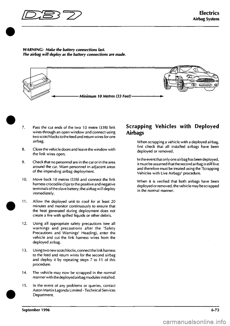
WARNING: Make the battery connections
last.
The airbag will deploy as the battery connections are made.
Minimum 10 Metres (33 Feet)-
7. Pass the cut ends of the two 10 metre (33ft) link
wires through an open window and connect using
two scotchlocks to the feed and return wires for one
airbag.
8. Closethe vehicle doors and leave the window with
the link wires open.
9. Check that no personnel are in the car or in the area
around the car. Warn personnel in adjacent areas
of the impending airbag deployment.
10.
Move back 10 metres (33ft) and connect the link
harness crocodile clips to the positive and negative
terminals ofthe slave battery; the airbag will deploy
immediately.
11.
Allow the deployed unit to cool for at least 20
minutes and monitor continuously to ensure that
the heat generated during deployment does not
create a fire with spilled liquids or other debris.
12.
Using all appropriate safety precautions (see all
warnings and precautions after the 'Safety
Precautions and Warnings' Heading), enter the
vehicle and cut the link harness wires from the
deployed airbag.
13.
Usingtwonewscotchlocks,connectthelinkharness
to the feed and return wires for the second airbag
and deploy it by repeating steps 7 to 11 of this
procedure.
14.
The vehicle may now be scrapped in the normal
manner with thedeployed airbag modules installed.
15.
In the event of any problems or queries, contact
Aston Martin Lagonda Limited - Technical Services
Department.
Scrapping Vehicles
Air bags
with Deployed
when scrapping a vehicle with a deployed airbag,
first check that all installed airbags have been
deployed or removed.
In the eventthatonly one airbag has beendeployed,
it must be assumed thatthe second airbag is still live
and therefore must be treated using the 'Scrapping
Vehicles with Live Airbags' procedure.
when it is verified that both airbags have been
deployed or removed, the vehicle may
be
scrapped
in the normal manner.
September 1996 6-73