torque ASTON MARTIN DB7 1997 User Guide
[x] Cancel search | Manufacturer: ASTON MARTIN, Model Year: 1997, Model line: DB7, Model: ASTON MARTIN DB7 1997Pages: 421, PDF Size: 9.31 MB
Page 326 of 421
^2?
Air Conditioning
System Recharging / Compressor Oil Check
Recharging the System
1.
Open the high side valve on the unit control panel.
If the messages PROGRAM and CHARGE are not
displayed press the CHG key to enter PROGRAM
mode.
2.
Key in the amount of refrigerant needed to recharge
the system and press ENTER.
3. Press the CHG key; the message AUTOMATIC and
the entered amount of refrigerant wi
11
be displayed.
The display counts down to zero as the charging
process proceeds. When the charging is complete
the message CPL is displayed.
If the refrigerant transfer is too slow the charging
unit emits a signal. If the message CHECK
REFRIGERANT is not displayed, close the high side
valve,
open the low side valve and start the air
conditioning system to pull the remainder of the
charge into the system.
If the refrigerant transfer will not complete and the
message CHECK REFRIGERANT is displayed, press
the HOLD/CONT key to interrupt the cycle then
reset the unit by pressing the RESET key. Recover
the refrigerant already charged into the system by
following the procedure for recovering the
refrigerant, add new refrigerant to the tank and
return to Step 1 to recharge the system.
4.
If the air conditioning system is not running start it
and let it run until the gauge pressure readings
stabilize (compare the gauge readings with the
system manufacturer's specifications).
Note:
Ensure
that the
readings
are accurate by closing
both the high and low side
valves
on the unit's control
panel.
5. Check the evaporator outlet temperature to make
sure that the air conditioning system is operating
properly (refer to the system manufacturer's
specifications for the proper temperature).
Compressor Oil Checic
Data
Special Tools
Sanden oil dipstick JD 149
Torque Figures
Oil filler plug 8-12 Nm
Procedure
Whenever a component has been replaced in the
refrigerator system or there is an obvious oil leak, the
following procedure should be carried out.
A Sanden oil dipstick and angle gauge are required in
order to carry out the check.
1.
Run the compressor for 10 minutes at engine idle
speed.
2.
Depressurise the system.
3. Lay the angle gauge across the flat surfaces of the
two front mounting lobes. Centre the bubble and
note the mounting angle.
4.
Remove the compressor from the vehicle.
3. Remove the plug from the oil filler hole
(1
Fig. 1).
4.
Rotate the counter weight (3 Fig. 1) on the front of
theclutchtoallowthedipstick(2 Fig. 1)to penetrate
to its fullest extent.
Figure 1.
5. Insert the dipstick to its stop position (4 Fig. 1). The
point of dipstick angle should be facing left.
6. Removethedipstickandchecktheoil levelagainst
the figures quoted in the chart below.
May 1996 8-49
Page 327 of 421
Air Conditioning
Compressor Oil Check ^^?
7.
Mounting
Degrees
0°
10°
20°
30°
40°
50°
60°
90°
Angle Acceptable
Increments
3-5
4-6
5-7
6-8
7-9
8-10
9-11
10-12
If the level indicated on the dipstick does not match
the increments given in the table for a particular
mounting angle, add or subtract oil to the midpoint
value.
Ensure that the "O" ring seal and seat are clean.
Coat the seal with compressor oil and refit the oil
filler
plug.
Torque tighten the plug to 8-12 Nm. Do not over
tighten the plug to stop a leak. If necessary, remove
the plug and fit a new oil
seal.
9. Refit the compressor.
10.
Recharge the system with refrigerant.
8-50 May 1996
Page 329 of 421
Air Conditioning Repair Procedures
Field Coil Renewal
/
Gasket Kit Renewal ffi^e^'^^
8.1.02.1 Field Coil Renewal 8.1.03.1 Renew Gasket
Kit
Procedure
1.
Open
the
bonnet
and fit a
wing cover.
2.
Depressurise
the air
conditioning system.
3. Remove
the
compressor.
4.
Remove
the
compressor drive clutch.
5. Remove
the
compressor pulley.
6. Slacken
the
field coil wire clamp screw
(Fig.
1) and
release
the
wire from
the
clamp.
10.
Remove
the
field coil retaining snap ring
and
detach
the
field
coil.
Clean
the
mating face
of the
compressor with
a
cloth moistened with
an
approved cleaning
fluid.
Position
the new
field coil
on the
compressor
and
fit
the
retaining snap
ring.
Route
the
wire
to the
compressor
and fit the
wire
clamp, tighten
the
securing screw.
11.
Fit the
compressor pulley.
12.
Fit the
compressor drive clutch.
13.
Fit the
compressor.
14.
Recharge
the air
conditioning system.
15.
Remove
the
wing cover
and
close
the
bonnet.
Data
Torque Figures
Cylinder head bolts 29.83
to 33.9 Nm.
Procedure
1.
Open
the
bonnet
and fit a
wing cover.
2.
Depressurise
the air
conditioning system.
3. Remove
the
compressor.
4.
Position
the
compressor
in a
vice, tighten
the
vice
onto
the
compressor body lugs.
5. Remove the outlet port blanking plate securing bolt
and detach
the
plate.
6. Remove
and
discard
the 'O'
ring seals from
the
outlet port.
7. Remove
the
compressor cylinder head securing
bolts,
detach
the
cylinder head.
8. Detach
the
valve plate from
the
compressor.
9. Remove
the
gaskets from
the
compressor.
10.
Remove
all
traces
of
gasket material from
the
mating surfaces
of the
cylinder head, valve plate
and cylinder block.
Figure
1.
11.
Position
new
gaskets (Fig.
1 -1
and 3) on the
valve
plate
(Fig. 1-2) and
then place
it on the
cylinder
block.
8-52 May
1996
Page 330 of 421
ES3^^
Air Conditioning Repair Procedures
Valve Plate Renewal
Figure
2.
12.
Position the cylinder head (Fig. 2-1) on the cylinder
block (Fig. 2-2), fit and tighten the securing bolts in
the sequence shown in Fig. 3.
8.1.04.1 Valve Plate Renewal
Data
Torque Figures
Cylinder head bolts 29.83 - 33.9 Nm
Procedure
1.
Open the bonnet and fit a wing cover.
2.
Depressurise the air conditioning system.
3. Remove the compressor.
4.
Position the compressor in a vice, tighten the vice
onto the compressor body lugs.
5. Remove the outlet port blanking plate securing bolt
and detach the plate.
6. Remove the 'O' ring seals from the compressor
outlet port.
figure 3.
13.
Fit new 'O' ring seals in the compressor outlet port,
position the outlet port blanking plate and fit and
tighten the securing bolt.
14.
Check and top up compressor oil
15.
Refit the compressor.
16.
Recharge the air conditioning system.
Figure 1.
7. Removethecylinder head securing boltsand detach
the cylinder head (Fig. 1-1) from the cylinder block.
8. Remove valve plate
(Fig.
1
-2) from the compressor.
9. Remove all traces of gasket material from the
mati
ng
surfaces of the cy
I
i nder
head
and compressor.
10.
Apply clean refrigerant oil to the gaskets and then
position them on the valve plate.
May 1996 8-53
Page 388 of 421

^
The Aston Martin Lagonda Diagnostic System
Users Guide
Signal Description
lACDTCY Idle Air Control Duty Cycle (% open)
lAT Intake Air Temperature - °C or raw input counts
lAT STAT Air Temperature - Temperature sensor failure
lAT-V Intake Air Temperature - Volts or raw counts
IGN Desired Ignition Timing - ° BTDC
INDS Input from manual lever position sensor (counts)
IPWA Injector Pulse Width in mS- Bank A (Cylinders
1
-3)
IPWB Injector Pulse Width in mS- Bank B (Cylinders 4-6)
LAMSE1 Current Short Term Fuel Trim 1, adjustment from stoich - (% of range)
LAMSE2 Current Short Term Fuel Trim 2, adjustment from stoich - (% of range)
LFC Low Speed Fan Status
LOOP Fuel Control -1 = Open Loop, 0 = Closed Loop
MAF MAX Maximum Mass Air Flow signal during normal running
MAF Raw MAF sensor output (A/D counts)
MAF STAT Mass Air Flow Meter - MAF sensor failure
MIL Mali Indicator Lamp Status -1 = Lamp On
Mis HI Cumulative misfires detected by misfire test (Hi bit).
Mis LO Cumulative misfires detected by misfire test (Lo bit).
Mis nc HI Cumulative misfires detected by a misfire test (Hi bit).
Mis nc LO Cumulative misfires detected by a misfire test.
Misi HI Cumulative misfires detected by cylinder
1
misfire test (Hi bit).
Misi LO Cumulative misfires detected by cylinder
1
misfire test (Lo bit).
Mis2 HI Cumulative misfires detected by cylinder 2 misfire test (Hi bit).
Mis2 LO Cumulative misfires detected by cylinder 2 misfire test (Lo bit).
Mis3 HI Cumulative misfires detected by cylinder 3 misfire test (Hi bit).
Mis3 LO Cumulative misfires detected by cylinder 3 misfire test (Lo bit).
Mis4 HI Cumulative misfires detected by cylinder 4 misfire test (Hi bit).
Mis4 LO Cumulative misfires detected by cylinder 4 misfire test (Lo bit).
Mis5 HI Cumulative misfires detected by cylinder 5 misfire test (Hi bit).
Mis5 LO Cumulative misfires detected by cylinder 5 misfire test (Lo bit).
Mis6 HI Cumulative misfires detected by cylinder 6 misfire test (Hi bit).
Mis6 LO Cumulative misfires detected by cylinder 6 misfire test (Lo bit).
MISF Misfire Monitor - 1 = Currently misfiring
ODCODES Total number of on-demand codes currently stored.
PGM CVS DC Purge Management Duty Cycle (% on)
PIP Profile ignition Pick-Up - PIP input level
PNP Park Neutral Position Switch
R-BIAS1 Rear bias trim (Bank 1, cylinders
1
-3)
R-BIAS2 Rear bias trim (Bank 2, cylinders 4-6)
RATCH Lowest TP reading during driving
TP MAX Maximum Throttle Potentiometer signal during normal running
TP STAT Throttle Position Sensor - TP sensor failure
TP Throttle Potentiometer - Volts or counts
TPR-V Raw counts from sensor
TQ-NET Net torque into the torque convertor
TRIP OBDII Drive Cycle Complete (except cat monitor) - 1 = Trip completed
TRIPCNT Number of Completed OBDII Trips
VS MAX Maximum Vehicle Speed signal during normal running
VS STAT Vehicle Speed Sensor mode flag
VS Vehicle Speed - MPH
WAC Wide Open Throttle A/C Cut-Off -1 = High (WOT Relay)
September 1996 9-37
Page 391 of 421
The Aston Martin Lagonda Diagnostic System
Users Guide ^=2?
Transmission Diagnostics
Automatic transmission DB7s are fitted with a GM4L80-
E gearbox electronically controlled by a Transmission
Control Unit (TCM)
The TCM is mounted on the rear left wheel
arch.
It may be
electronically accessed from the upper diagnostic socket.
The TCM continuously monitors requests made by the
driver via the gear selector, throttle pedal, mode switch,
etc. This data is used in conjunction with speed input from
the transmission unit to calculate the optimum shift points
undercurrentconditions.Shiftpressureand ignition retard
are also controlled from this data to enhance shift quality
and reduce transmission wear.
TheTCM also detects faults within the transmission system
and stores the relevant fault codes for later analysis.
Gearshifts are controlled by two solenoid valves and a
pressure regulator within the transmission valve block
assembly.
If a serious fault occurs, the TCM removes all electrical
power from these valves and the transmission defaults to
a 'limp home' condition. In this state, only mechanical
selection of either reverse or second gear is available.
Gearshift Timing
Inputs from the performance mode switch (Sport, Normal
or 1st Gear Inhibit) and the throttle position sensor are
used to modify transmission gearshift operation
as
required
by the driver.
Sport mode raises the roadspeed at which gearshifts occur
enabling higher acceleration rates for the vehicle.
1st gear inhibit prevents engagement of first gear to reduce
the risk of wheel slip in icy conditions.
The throttle position sensor signal is continuously
monitored by the TCM to detect a rapid throttle opening.
If the throttle position sensor signal rises rapidly to above
4.5 volts, a 'Kickdown' condition is initiated. In this
condition,
upshifts are delayed to higher road speeds to
provide the higher acceleration required for overtaking
etc.
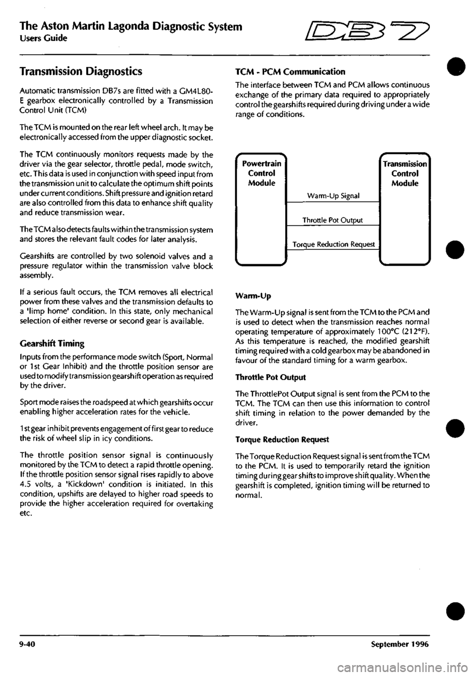
TCM - PCM Communication
The interface between TCM and PCM allows continuous
exchange of the primary data required to appropriately
control the gearshifts required during driving under
a
wide
range of conditions.
Powertrain
Control
Module
^.. ^
Warm-Up Signal
Throttle Pot Output
Torque Reduction Request
^ •- -^ Transmission
Control
Module
Warm-Up
The Warm-Up signal is sent from the TCM to the PCM and
is used to detect when the transmission reaches normal
operating temperature of approximately 100°C (212"'F).
As this temperature is reached, the modified gearshift
timing required with a cold gearbox may be abandoned in
favour of the standard timing for a warm gearbox.
Throttle Pot Output
The ThrottlePot Output signal is sent from the PCM to the
TCM.
The TCM can then use this information to control
shift timing in relation to the power demanded by the
driver.
Torque Reduction Request
The Torque Reduction Requestsignai
is
sent from the TCM
to the PCM. it is used to temporarily retard the ignition
timing during gear shifts to improve shift quality. When the
gearshift is completed, ignition timing will be returned to
normal.
9-40 September 1996
Page 392 of 421
^^?
The Aston Martin Lagonda Diagnostic System
Users Guide
Transmission Diagnostics
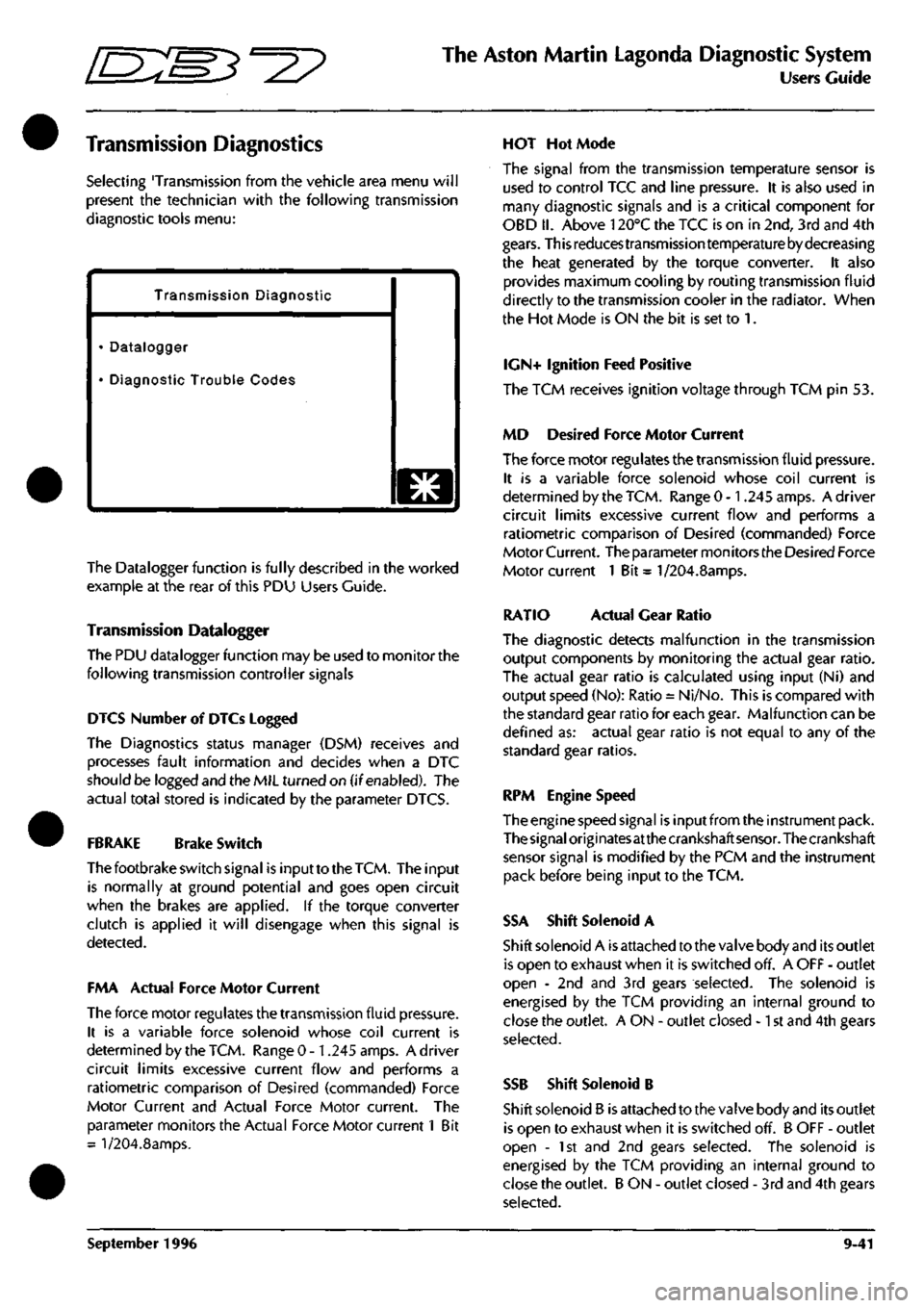
Selecting 'Transmission from the vehicle area menu will
present the technician with the following transmission
diagnostic tools menu:
Transmission Diagnostic
• Datalogger
• Diagnostic Trouble Codes
o
The Datalogger function is fully described in the worked
example at the rear of this PDU Users Guide.
Transmission Datalogger
The PDU datalogger function may be used to monitor the
following transmission controller signals
DIGS Number of DTCs Logged
The Diagnostics status manager (DSM) receives and
processes fault information and decides when a DTC
should be logged and the MIL turned on (if enabled). The
actual total stored is indicated by the parameter DTCS.
FBRAKE Brake Switch
The footbrake switch signal is input to the
TCM.
The input
is normally at ground potential and goes open circuit
when the brakes are applied. If the torque converter
clutch is applied it will disengage when this signal is
detected.
FMA Actual Force Motor Current
The force motor regulates the transmission fluid pressure.
It is a variable force solenoid whose coil current is
determined by the TCM. Range 0 -1.245 amps. A driver
circuit limits excessive current flow and performs a
ratiometric comparison of Desired (commanded) Force
Motor Current and Actual Force Motor current. The
parameter monitors the Actual Force Motor current 1 Bit
= l/204.8amps.
HOT Hot Mode
The signal from the transmission temperature sensor is
used to control TCC and line pressure. It is also used in
many diagnostic signals and is a critical component for
OBD II. Above 120°C the TCC is on in 2nd, 3rd and 4th
gears.
This reduces transmission temperature by decreasing
the heat generated by the torque converter. It also
provides maximum cooling by routing transmission fluid
directly to the transmission cooler in the radiator. When
the Hot Mode is ON the bit is set to 1.
IGN+ Ignition Feed Positive
The TCM receives ignition voltage through TCM pin 53.
MD Desired Force Motor Current
The force motor regulates the transmission fluid pressure.
It is a variable force solenoid whose coil current is
determined by the TCM. Range 0 -1.245 amps. A driver
circuit limits excessive current flow and performs a
ratiometric comparison of Desired (commanded) Force
Motor Current. The parameter mon itors the Desired Force
Motor current 1 Bit = 1/204.8amps.
RATIO Actual Gear Ratio
The diagnostic detects malfunction in the transmission
output components by monitoring the actual gear ratio.
The actual gear ratio is calculated using input (Ni) and
output speed (No): Ratio = Ni/No. This is compared with
the standard gear ratio for each gear. Malfunction can be
defined as: actual gear ratio is not equal to any of the
standard gear ratios.
RPM Engine Speed
The engine speed signal is input from the instrument pack.
The
signal
origi
nates
at the crankshaft
sensor.
The crankshaft
sensor signal is modified by the PCM and the instrument
pack before being input to the TCM.
SSA Shift Solenoid A
Shift solenoid A is attached to the valve body and its outlet
is open to exhaust when it is switched off. A OFF - outlet
open - 2nd and 3rd gears selected. The solenoid is
energised by the TCM providing an internal ground to
close the outlet. A ON - outlet closed -1 st and 4th gears
selected.
SSB Shift Solenoid B
Shift solenoid B is attached to the valve body and its outlet
is open to exhaust when it is switched off. B OFF - outlet
open - 1st and 2nd gears selected. The solenoid is
energised by the TCM providing an internal ground to
close the outlet. B ON - outlet closed - 3rd and 4th gears
selected.
September 1996 9-41
Page 393 of 421
The Aston Martin Lagonda Diagnostic System
Users Guide ^7
TCCS Torque Convertor Clutch Solenoid
The torque converter clutch solenoid is mounted on the
valve body. The signal is Pulse Width Modulated at 32Hz
to provide closed loop control of the pressure across the
converter clutch plates. 1 bit = 0.39% Range 0 to 100%
TP Throttle Position
This is provided by the EECV Engine Management System
as a Pulse Width Modulated signal derived from the
throttle position signal read by that module from the
throttle position sensor.
TCS Torque Convertor Slip
Torque converter slip is defined
as
the difference between
the Input/turbine (ni) speed and the Engine speed (Ne):
Slip = Ne-Ni. The PWM duty cycle may increase from 0
to 100% when TCC is fully applied. In practice a 100%
duty cycle will be achieved only if
a
large slip is detected.
Normal ly only a 50 to 95% duty cycle will be required for
full application of the TCC. Slip is expressed in rpm. 1 Bit
- 1/8 rpm. Range -4096 to +4096 rpm.
TCSW Transmission Control Switch
A three position switch allows the driver to select Sport,
Normal or 1st Gear Inhibit mode. When 'Sport' is selected
gearshifts take place at higher engine revs. When '1st
Gear Inhibit' is selected, the transmission only operates in
the higher forward ratios to prevent wheel slip in icy
conditions.
TISSA Turbine Input Shaft Speed
Turbine speed is the speed of the input shaft of the
transmission measured by the input speed sensor mounted
on the transmission. An alternating waveform is induced
in the sensor by 31 serrations on the forward clutch
housing as it rotates. The waveform frequency and
amplitude is low at low speeds and high at high speeds.
The TCM changes this signal into a digital signal. 1 bit =
1/8 RPM. Range: 0 - 8192 RPM.
TOS+ Transmission Output Speed
The output speed sensor is mounted on the transmission
case and measures the speed of the output shaft. As the
shaft rotates an alternating waveform is induced in the
sensor which varies in frequency and voltage. The wave
form is converted into
a
digital signal by the TCM and used
to control TCC, line pressure, shift timing and torque
management. 1 bit = 1/8 RPM. Range 0-8192 RPM
TRX Transmission Control Switch X
TRY Transmission Control Switch Y
TRZ Transmission Control Switch Z
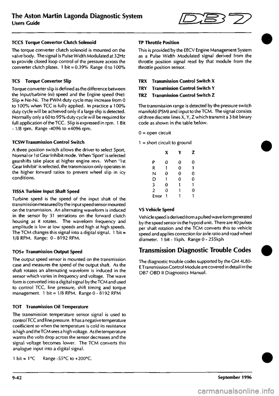
The transmission range is detected by the pressure switch
manifold (PSM) and input to the
TCM.
The signal consists
of three discrete lines X, Y, Z which transmit a 3 bit binary
code as shown in the table below.
0 = open circuit
1 = short circuit to ground
X Y Z
p
R
N
D
3
2
Error
0
1
0
1
0
0
1
0
0
0
0
1
1
1
0
1
0
0
1
0
1
VS Vehicle Speed
Veh icie speed
is
derived from
a pu Ised
wave form generated
by the speed sensor in the hypoid unit. There are 40 pulses
per shaft rotation and the TCM converts this to vehicle
speed and applies correction for axle ratio and road wheel
diameter. 1 bit -
1
kph. Range 0 - 255kph
Transmission Diagnostic Trouble Codes
The diagnostic trouble codes supported by the CM 4L80-
E
Transmission Control Module are covered indetail inthe
DB7 OBD II Diagnostics Manual.
TOT Transmission Oil Temperature
The transmission temperature sensor signal is used to
control TCC and line
pressure.
It
has a
negative temperature
coefficient so when the temperature is cold its resistance
is high and the TCM sees
a
high voltage. Asthe temperature
warms the volts drop across the sensor decreases and the
signal voltage becomes lower. The TCM converts this
analogue input into a digital signal.
1 bit =
1
°C Range -55°C to +200°C.
9-42 September 1996