tow ASTON MARTIN DB7 1997 Workshop Manual
[x] Cancel search | Manufacturer: ASTON MARTIN, Model Year: 1997, Model line: DB7, Model: ASTON MARTIN DB7 1997Pages: 421, PDF Size: 9.31 MB
Page 5 of 421

//—-^
^^^^5~^
' -^ ^ Introduction
Safety Precautions
Safety Precautions (continued)
Electrical Equipment
1.
Ensure that electrical equipment is in safe working order before use.
2.
Inspect power leads of all mains electrical equipment for damage and security, and check that it is properly
earthed.
3. Ensure that electrical equipment is protected by a fuse of the correct current rating.
4.
Disconnect the battery before commencing repair operations to the electrical system, fuel system and engine
or when working beneath the vehicle.
Exhaust Fumes
Engines should not be run in confined spaces, exhaust fumes contain harmful and toxic substances including carbon
monoxide which can prove fatal if inhaled. Engines must only be run where there is fume extraction equipment in
operation or where there is adequate ventilation.
Fire Precautions
1.
Ensure that a suitable form of fire extinguisher is conveniently located near the work area.
2.
Keep oils, solvents and combustible materials away from naked flames and other sources of ignition.
3. Ensure that NO SMOKING signs are posted around areas where combustible materials and vapour may be
present and ensure that the warnings are strictly observed.
4.
Ensure that dry sand is available to soak up any spillage of fuel or other flammable solutions.
5. Fume extraction equipment must be available and in full working order to remove combustible and toxic
vapours.
6. All personnel should be aware of the fire drill procedures and precautions.
Jacking and Lifting
1.
The recommended procedures for lifting, jacking and towing are included latefin this seetion-and must be
strictly observed to ensure personal safety.
2.
Always use a vehicle hoist, ramp or pit for working beneath the car in preferencetd^&^cking
3. Never rely on a jack to support a car independently, use axle stands or blocks carefully pJaQed at the jacking
points to provide rigid support.
4.
When working beneath a vehicle, chock the wheels as well as applying the handbrake.
5. Ensure that the vehicle is standing on firm level ground before jacking or lifting.
5. Check any lifting equipment used has adequate capacity for the load being lifted and is ih"fdll working order.
Tools and Equipment
1.
Do not leave tools, equipment, spilt oil, etc. around or on the work area.
2.
Ensure that tools and equipment used are in good condition; do not use damaged or defective tools or
equipment.
3. Do not apply heat in an attempt to free stiff nuts or fittings; as well as causing damage to protective coatings,
there is a risk of damage to electronic equipment and brake lines from stray heat.
4.
Use the recommended service tool where instructed to do so.
April 1997 v
Page 266 of 421
^=2?
Body and Trim
Roof Hydraulic Control System
9. Position the rear edge of the roof to the body.
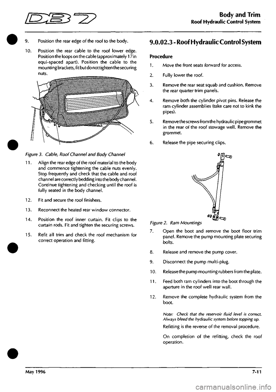
10.
Position the rear cable to the roof lower edge.
Position the loops on the cable (approximately 17in
equi-spaced apart). Position the cable to the
mou nti ng
brackets,
fit but do not tighten the
secu
ring
nuts.
Figure 3. Cable, Roof Channel and Body Channel
11.
Align the rear edge of the roof material to the body
and commence tightening the cable nuts evenly.
Stop frequently and check that the cable and roof
channel
are
correctly bedding into the body channel.
Continue tightening and checking until the roof is
fully seated in the body channel.
12.
Fit and secure the roof finishers.
13.
Reconnect the heated rear window connector.
14.
Position the roof inner curtain. Fit clips to the
curtain rods. Fit and tighten the securing screws.
15.
Refit all trim and check the roof mechanism for
correct operation and fitting.
9.0.02.3 - Roof Hydraulic
Control
System
Procedure
1.
Move the front seats forward for access.
Fully lower the roof.
2.
3.
4.
6.
Remove the rear seat squab and cushion. Remove
the rear quarter trim panels.
Remove both the cylinder pivot pins. Release the
ram cylinder assemblies (take care not to kink the
pipes).
Remove the screws from the hydraulicpipegrommet
in the rear of the roof stowage
well.
Remove the
grommet.
Release the pipe securing clips.
Figure 2. Ram Mountings
7. Open the boot and remove the boot floor trim
panel.
Remove the pump mounting plate securing
bolts.
8. Release and remove the pump cover.
9. Disconnect the pump multi-plug.
10.
Releasethe pump mounting rubbers from the plate.
11.
Feed both ram cylinders into the boot through the
aperture in the roof well rear
wall.
12.
Remove the complete hydraulic system from the
boot.
Note: Check that the reservoir fluid level is correct.
Always bleed the hydraulic
system
before topping up.
Refitting is the reverse of the removal procedure.
On completion of the refitting, check the roof
operation.
May 1996 7-11
Page 276 of 421
"^7
Body and Trim
Cleaning of Alcantara Trim
Cleaning of Alcantara Trimmed Roof Lining and Interior Components
Recommendations
1.
Clean the stain immediately.
Clean the stain working from the edge to the centre of the spot to prevent a ring forming.
Delicately remove most of the dirt with a blunt scraper and immediately blot the spot with a clean white cloth.
Once you've identified the type of stain, follow the instructions in the spot removal chart.
Never pour a solvent directly on the spot; instead pour the solvent on a clean cloth.
After you've applied the spot remover, remove it with a dry clean cloth. Afterwards, brush the area against the
material nap.
7. Let the spot dry. Do not sit on a humid part. Afterwards, vacuum the spot with a vacuum cleaner.
Spot Removal Chart
Type of
Stain
Alcohol-Liquors
Beer
Coffee, Tea, Milk
Chocolate, Confectionary
Paints
Cosmetics
Grass, Plants
Chewing Gum
Ink
Marmalade, Syrup, Fruit Juice
Oil,
Grease
Ballpoint Pen
Wine Beverages
Cleaning Product and
Cleaning Method
Wash with mild soap, then blot with denatured alcohol
Blot with lukewarm water (max 50°C) and denatured alcohol at 3%
Washwithmildsoap. If the stain persists, blot with denatured alcohol or ammonia diluted
at 10%.
Blot with lukewarm water (max 50°C) or with ammonia diluted at 5%.
Oil Paint - Blot with ethyl alcohol then wash with mild soap.
Water Based Paint - If the stain is fresh, blot with cold water. An old stain is very difficult
to remove, consult a specialist.
Apply ethyl alcohol or perchloroethylene, then wash with mild soap. If the stain persists,
use ammonia diluted at 5% or denatured alcohol.
Blot with lukewarm water (max 50°C) then wash with mild soap.
Blot with acetone.
Remove as much as possible with a paper towel. Blot with a solution of 30% denatured
alcohol and 70% water, then wash with mild soap. Lemon juice also gives good results.
Blot with lukewarm water (max 50°C). If the stain persists, use ethyl alcohol or
perchloroethylene
Blot with denatured alcohol, then wash with mild soap.
Blot with perchloroethylene and denatured alcohol.
Blot with water and vinegar (50%), then wash with mild soap.
May 1996 7-21
Page 355 of 421
The Aston Martin Lagonda Diagnostic System
Installation Instructions "^P
Component Identification
Base Station (Fig
1
-16)
The Base Station is a wall or bench mounted steel
unit on which up to two Portable Diagnostic Units
and a Vehicle Interface Adaptor can be stored.
Portable Diagnostic Unit (PDU) (Fig 1-15)
The PDU is a hand held diagnostic tool utilising a
touch sensitive screen and serial communications
capability
Electronics Module
The Electronics Module is located behind the base
station door (Fig
1
-17) and facilitates the charging
of the PDU battery. Also contained in the module
is
the CD-ROM drive (Fig
1
-23) for the storage of
al I
system software. The PDU must be connected to
the electronic modu le whenever it is located on the
base station.
Vehicle interface Adaptor (VIA) (Fig
1
-14)
The VIA enables the PDU to interface with vehicle
systems not equipped with serial communications.
Vehicle Battery Adaptor (VBA)
The VBA provides the correct voltage to power the
PDU from the vehicle battery and also protects the
PDU from any interference from the vehicles
electrical systems.
Controls
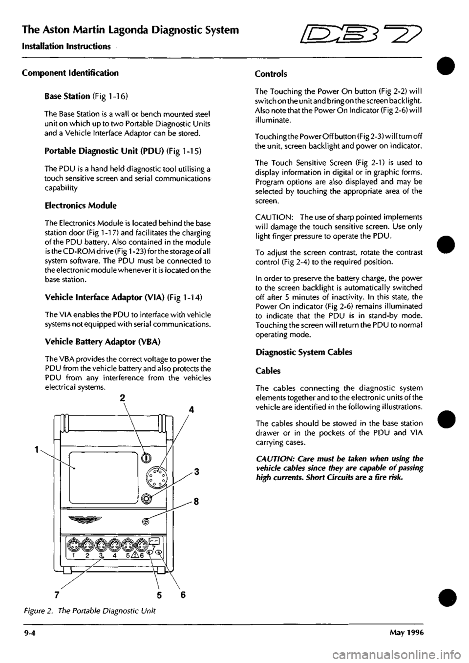
The Touching the Power On button (Fig 2-2) will
switch on the unit and bringon the screen backlight.
Also note that the Power On Indicator (Fig 2-6) will
illuminate.
Touching the Power Off button (Fig 2-3) will turn off
the unit, screen backlight and power on indicator.
The Touch Sensitive Screen (Fig 2-1) is used to
display information in digital or in graphic forms.
Program options are also displayed and may be
selected by touching the appropriate area of the
screen.
CAUTION:
The use of sharp pointed implements
will damage the touch sensitive screen. Use only
light finger pressure to operate the PDU.
To adjust the screen contrast, rotate the contrast
control (Fig 2-4) to the required position.
In order to preserve the battery charge, the power
to the screen backlight is automatically switched
off after 5 minutes of inactivity. In this state, the
Power On indicator (Fig 2-6) remains illuminated
to indicate that the PDU is in stand-by mode.
Touching the screen will return the PDU to normal
operating mode.
Diagnostic System Cables
Cables
The cables connecting the diagnostic system
elements together and to the electronic units of the
vehicle are identified in the following illustrations.
The cables should be stowed in the base station
drawer or in the pockets of the PDU and VIA
carrying cases.
CAUTION: Care must be taken when using the
vehicle cables since they are capable of
passing
high currents. Short Circuits are a fire
risk.
7 5 6
Figure 2. The Portable Diagnostic Unit
9-4 May 1996
Page 374 of 421
^?
The Aston Martin Lagonda Diagnostic System
Installation Instructions
1.
Switch off the PDU and remove all cables.
2.
Remove the cover screw (Fig 23) and remove the cover.
3. If damaged, remove the old foam gasket from the cover and replace with the new one supplied.
4.
Note the orientation of the connector. Disconnect the connector and remove the old battery pack.
5. Fit and connect the new battery pack (Fig 24) with the black cable towards the touch screen.
6. Refit the cover and cover screw.
7. Refer to the Battery Charging instructions for recharging times.
Changing the Dust Filter
The electronic module has a dust filter fitted to the underside of the module. Every three months a new filter wil
be supplied. To change the filter, proceed as follows:
1.
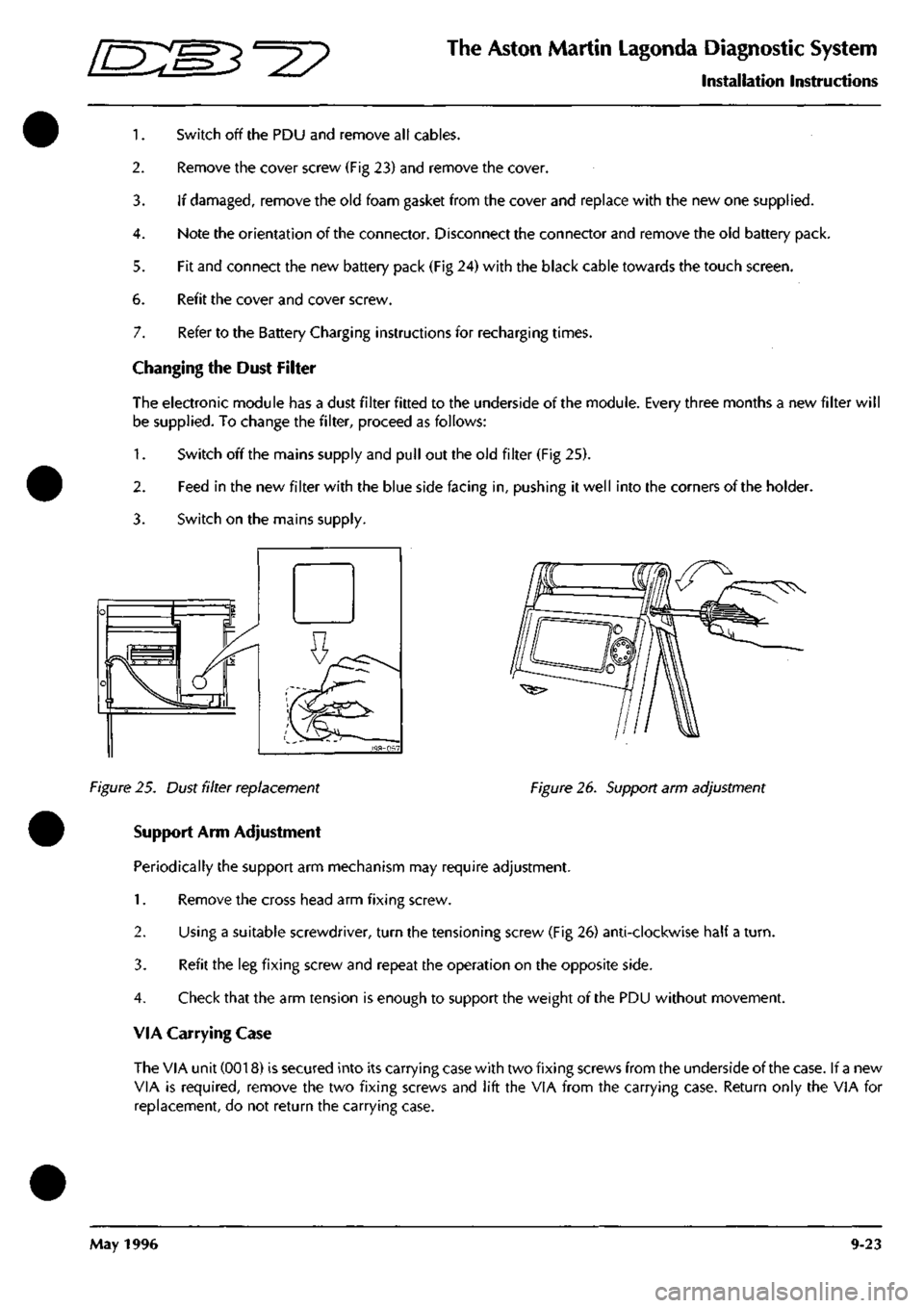
Switch off the mains supply and pull out the old filter (Fig 25).
2.
Feed in the new filter with the blue side facing in, pushing it well into the corners of the holder.
3. Switch on the mains supply.
Figure 25. Dust filter replacement Figure 26. Support arm adjustment
Support Arm Adjustment
Periodically the support arm mechanism may require adjustment.
1.
Remove the cross head arm fixing screw.
2.
Using a suitable screwdriver, turn the tensioning screw (Fig 26) anti-clockwise half a
turn.
3. Refit the leg fixing screw and repeat the operation on the opposite side.
4.
Check that the arm tension is enough to support the weight of the PDU without movement.
VIA Carrying Case
The VIA unit (0018) is secured into its carrying case with two fixing screws from the underside of the case. If a new
VIA is required, remove the two fixing screws and lift the VIA from the carrying case. Return only the VIA for
replacement, do not return the carrying case.
May 1996 9-23