compressor ASTON MARTIN DB7 1997 Owner's Manual
[x] Cancel search | Manufacturer: ASTON MARTIN, Model Year: 1997, Model line: DB7, Model: ASTON MARTIN DB7 1997Pages: 421, PDF Size: 9.31 MB
Page 311 of 421
Air Conditioning
Refrigeration /s:s^°27
Refrigeration
Safety Precautions
The air conditioning system is designed to use only
Refrigerant E134A (dichlorodifluoromethane). Extreme
care must betaken NOT to use
a
methylchloride refrigerant.
The chemical reaction between methylchloride and the
aluminium parts ofthe compressor results in the formation
ofproductswhich burn spontaneously on exposure toair,
or decompose with violence in the presence of moisture.
The suitable refrigerant is supplied under the following
names.
El 34A KLEA or equivalent
Warning: Take care when handling refrigerant. Serious
damage will occur if it is allowed to come into
contact with the eyes. Always wear with goggles
and gloves when working with refrigerant
First Aid
If refrigerant should come into contact with the
eyes or
skin,
splash the eyes or affected area with
cold water for several minutes. DO NOT RUB. As
soon as possible thereafter, obtain treatment from a
Doctor or an eye specialist.
Good Practice
1.
Protective sealing plugs must be fitted to all
disconnected pipes and units.
2.
Theprotectivesealingpiugsmustremain inposition
on ail replacement components and pipes until
immediately before assembly.
3. Any part arriving for assembly without sealing
plugs in position must be returned to the supplier as
defective.
4.
It is essential that a second backing spanner is
always used when tightening or loosening all joints.
This minimises distortion or strain on components
or connecting hoses.
5. Components must not be lifted by connecting
pipes,
hoses or capillary tubes.
6. Care must be taken not to damage fins on the
condenser or evaporator matrices. Any damage
must be rectified by the use of fin combs.
7. Before assembly oftube and hosejoints, use
a
small
amount of clean new refrigerant oil on the sealing
seat.
8. Refrigerant oil for any purpose must be kept very
clean and capped at all times. This prevents the oil
absorbing moisture.
9. Before assembly the condition of joints and flares
must be examined. Dirt and even minor damage
will cause leaks at the high pressure points
encountered in the system.
10.
Dirty end fitting can only be cleaned using a cloth
wetted with alcohol.
11.
Afterremovingsealingplugsand immediatelybefore
assembly, visually check the bore of pipes and
components. Where any dirt or moisture is
discovered,
the part must be rejected.
12. Ail components must be allowed to reach room
temperature before sealing plugs are removed.
This prevents condensation should the component
be cold initially.
13.
Before finally tightening hose connections ensure
that the hose lies in the correct position, is not
kinked or twisted and will not be trapped by
subsequent operations, e.g., refitting or closing
bonnet.
14.
Check that hoses are correctly fitted in clips or
straps.
15.
The compressor must be stored horizontally with
the sump down. It must not be rotated before fitting
and charging. Do not remove the shipping plate
until immediately before assembly. Always use
new "O" ring seals in those joints that incorporate
them.
"O" ring seals should be coated with
compressor oil before fitting.
16.
Components or hoses removed must be sealed
immediately after removal.
1 7. Afterthe system has been opened the receiver-drier
must be renewed.
18.
Before
testing,
run the engine until normal running
temperature is reached. This ensures that sufficient
vacuum is available for test. For cooling tests the
engine must be running for the compressor clutch
to operate.
8-34 May 1996
Page 312 of 421
'^T?
Air Conditioning
Compressors
Compressors
Compressor Clutch Control
The compressor
pu I
ley
is
driven continuously when
the engine is running. An electromagnetic clutch
allows the compressortobeengagedordisengaged.
The clutch is energised by battery supply voltage
when the clutch relay RF3 is closed by a signal from
the ECM (pin 21) via the engine management
system.
6^
o>o 1
4
Figure 1
Figure 2
Key to Fig. 2
1.
2.
3.
4.
5.
Condenser
Clutch relay supply
Compressor clutch
HSLP switch
Protection diode
Earth-ground
Key to Fig. 1
1.
+ve battery supply
2.
Clutch relay
3. Compressor clutch
4.
Pin 20 ECM supply to clutch relay solenoid
5. Earth-Ground
6. Earth-Ground
Trinary Switch
High Side Low Pressure Switch
The high side low pressure switch (HSLP) is
connected in the earth-ground return lead of the
compressor clutch
coil.
The switch is a function of
the trinary switch and monitors the pressure on the
high side of the refrigeration system. If the pressure
drops below 25 psi (+ 5 psi) the contacts open to de-
energise the clutch coil and disengage the clutch.
Low pressure occurs when there is a fault in the
system,
and the HSLP switch contacts remain open
until the fault has been rectified.
The condenser (Fig, 3) consists of a refrigerant coil
mounted in a series of thin cooling fins to provide
maximum heat transfer in the minimum amount of
space.
It is mounted directly behind the car radiator
and receives the fu
11
flow of ram air induced by the
forward motion of the car and the suction of the
cool ing
fan.
Refrigerant enters the inlet at the top of
the condenser as a high pressure hot vapour. As the
vapour passes down through the condenser coils
cooled by ram air, a large quantity of heat is
transferred to the outside air and the refrigerant
changes to a high pressure warm liquid.
May 1996 8-35
Page 313 of 421
Air Conditioning
Compressors ^?
Evaporator
Figure 3.
Receiver-Drier
The receiver drier (Fig. 1) accepts high pressure
warm refrigerant liquid from the condenser and
del ivers it via an expansion valve to the evaporator.
It contains a quantity of molecular sieve desiccant
to remove moisture from the refrigerant, and
a
fi Iter
to removecontaminants.lt also
a
providesa reservoir
of refrigerant for the evaporator under varying
operating conditions.
The evaporator consists of a refrigerant coil mounted
in a series of thin fins to provide a maximum
amount of heat transfer in a minimum amount of
space.
It is housed in the air conditioning unit and
all air entering the system passes across its
coil.
The evaporator receives refrigerant from the
thermostatic expansion valve as a low pressure
cold atomised liquid. As this cold liquid passes
through the evaporator coils, it absorbs heat from
the surrounding air and changes into
a
low pressure
warm vapour.
Expansion Valve
The expansion valve is the dividing point between
the high and low pressure sides of the system. It
automatically meters high pressure, warm liquid
refrigerant via a metering orifice into the low
pressure, cold side of the evaporator matrix. The
valve senses outlet pipe temperature, inlet pipe
pressure and regulates the flow of refrigerant into
the evaporator to ensure that only vaporised
refrigerant appears at the outlet.
Figure 1.
8-36 May 1996
Page 314 of 421
^?
Air Conditioning
Sanden Compressor SD7H15
Sanden Compressor SD7H15
The Sanden SD7H15 compressor
is a 7
cylinder
machine with
a
bore
of
29.3
mm (1.15 in) and a
stroke
of
32.8
mm (1.29
inches).
The displacement
per
revolution
is
155cc
(9.5
cubic inches).
The magnetic clutch
is
engineered with
the
compressor
as a
complete assembly resulting
in a
relatively small unit
of
lightweight construction.
The compressor may be mounted up to 90° from
its
upright position.
The compressor incorporates
a
lubrication system
which reduces the
oil
circulation ratio
to a
level
of
less than
2% at 1800 rpm.
An
oil
deflector
and
positive pressure differential
lubrication system promotes oiling
to the
cylinder
wall,
piston
rod
assemblies, main bearings
and
shaft
seal,
and
ensures that
oil
circulation
to the
refrigeration circuit
is
kept
to a
minimum.
The
compressor ischarged
with!
35 cc(4.6fluid ounces)
ofSunico NoSGSoil at the factory. Only this oil
or
oneoftheequivalentoilsdetailed below should
be
used.
Key
1.
2.
3.
4.
5.
6.
7.
8.
9.
10.
11.
12.
13.
14.
15.
16.
to Fig. 2.
Service port
Cylinder head
Hose connection
Anti-rotation gear
Oil filler plug
Planet plate
Clutch bearing
Electromagnetic clutch
Valve plate assembly
Cylinder and valve plate gasket
Cylinder block
Piston
Cam rotor
Needle thrust bearing
Front housing and 'O' ring
Shaft seal
Compressor Oils
Suni
CO
No 5GS
Texaco Capella E
Virginia Chemicals 500 Viscosity
13
14 15 16
Figure
2.
May
1996
8-37
Page 316 of 421
^=2?
Air Conditioning
System Checking with the Manifold Gauge Set
System Checking with the Manifold
Gauge Set
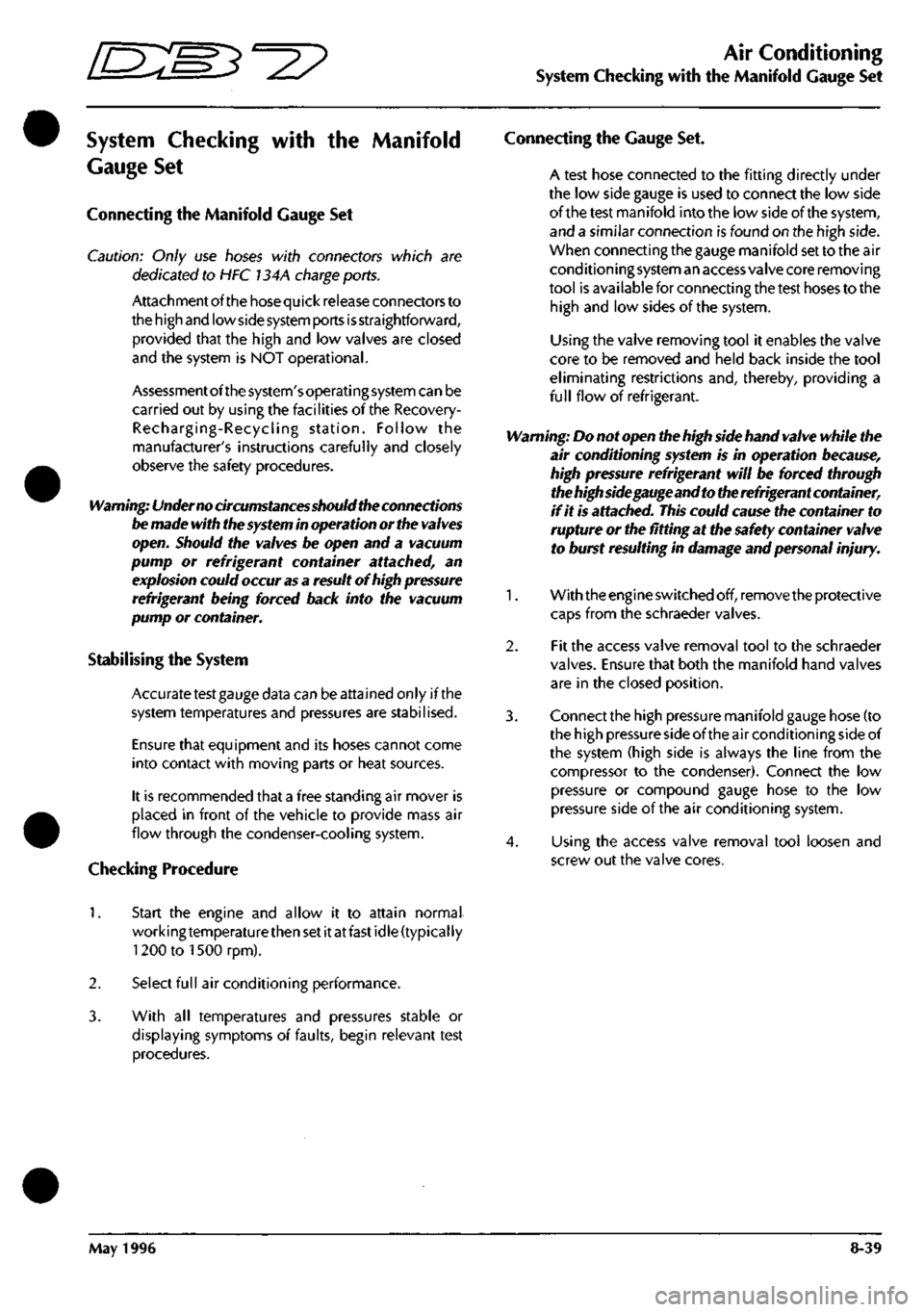
Connecting the Manifold Gauge Set
Caution: Only use hoses with connectors which are
dedicated to HFC 134A charge ports.
Attachmentofthehosequick release connectors to
the high and low side
system
ports
is
straightforward,
provided that the high and low valves are closed
and the system is NOT operational.
Assessment ofthe system's operating system can be
carried out by using the facilities ofthe Recovery-
Recharging-Recycling station. Follow the
manufacturer's instructions carefully and closely
observe the safety procedures.
Warning: Under no circumstances should the connections
be made with the
system
in operation or the
valves
open. Should the valves be open and a vacuum
pump or refrigerant container attached, an
explosion could occur
as
a result of high pressure
refrigerant being forced back into the vacuum
pump or container.
Stabilising the System
Accurate test gauge data can be attained only if the
system temperatures and pressures are stabilised.
Ensure that equipment and its hoses cannot come
into contact with moving parts or heat sources.
It is recommended that a free standing air mover is
placed in front of the vehicle to provide mass air
flow through the condenser-cooling system.
Checking Procedure
Connecting the Gauge Set.
A test hose connected to the fitting directly under
the low side gauge is used to connect the low side
ofthe test manifold into the low side ofthe system,
and a similar connection is found on the high side.
When connecting the gauge manifold set to the air
cond ition i ng system an access va Ive core removi ng
tool is available for connecting the test hoses to the
high and low sides ofthe system.
Using the valve removing tool it enables the valve
core to be removed and held back inside the tool
eliminating restrictions and, thereby, providing a
full flow of refrigerant.
Warning: Do not open the high side hand valve while the
air conditioning system is in operation because,
high pressure refrigerant will be forced through
the high side gauge and to the refrigerant container,
if it is attached.
This
could cause the container to
rupture or the fitting at the safety container valve
to burst resulting in damage and personal injury.
1.
With theengineswitched off, remove the protective
caps from the schraeder valves.
2.
Fit the access valve removal tool to the schraeder
valves. Ensure that both the manifold hand valves
are in the closed position.
3. Connect the high pressure manifold gauge hose (to
the high pressure side of the air conditioning side of
the system (high side is always the line from the
compressor to the condenser). Connect the low
pressure or compound gauge hose to the low
pressure side ofthe air conditioning system.
4.
Using the access valve removal tool loosen and
screw out the valve cores.
1.
Start the engine and allow it to attain normal
working temperature then set it at fast idle (typically
1200 to ISOOrpm).
2.
Select full air conditioning performance.
3. With all temperatures and pressures stable or
displaying symptoms of faults, begin relevant test
procedures.
May 1996 8-39
Page 318 of 421
=2?
Air Conditioning
System Checking with the Manifold Gauge Set
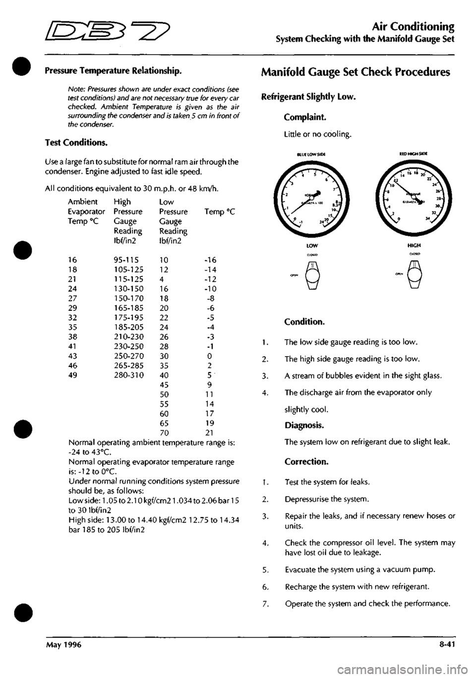
Pressure Temperature Relationship.
Note:
Pressures
shown are under exact conditions
(see
test
conditions) and
are
not
necessary
true for every
car
checked.
Ambient Temperature is given as the air
surrounding the
condenser
and
is
taken 5 cm in front of
the
condenser.
Test Conditions.
Use a large fan to substitute for normal ram air through the
condenser. Engine adjusted to fast idle speed.
All conditions equivalent to 30 m.p.h. or 48 km/h.
Ambient
Evaporator
Temp °C
16
18
21
24
27
29
32
35
38
41
43
46
49
High
Pressure
Gauge
Reading
Ibf/in2
95-115
105-125
115-125
130-150
1
50-170
165-185
175-195
185-205
210-230
230-250
250-270
265-285
280-310
Low
Pressure
Gauge
Reading
Ibf/in2
10
12
4
16
18
20
22
24
26
28
30
35
40
45
50
55
60
65
70
Ten
-16
-14
-12
-10
-8
-6
-5
-4
-3
-1
0
2
5
9
11
14
17
19
21
Normal operating ambient temperature range is:
-24 to 43°C.
Normal operating evaporator temperature range
is:-12toO°C.
Under normal running conditions system pressure
should be, as follows:
Lowside:1.05to2.10kgf/cm21.034to2.06bar15
to 30 ibf/in2
High side: 13.00 to 14.40 kgf/cm2 12.75 to 14.34
bar185to205lbf/in2
Manifold Gauge Set Check Procedures
Refrigerant Slightly Low.
Complaint.
Little or no cooling.
1.
2.
3.
4.
1.
2.
3.
4.
5.
6.
7.
BLUE LOW SIDE
KED
HIGH SIDE
Condition.
The low side gauge reading is too low.
The high side gauge reading is too low.
A stream of bubbles evident in the sight glass.
The discharge air from the evaporator only
slightly
cool.
Diagnosis.
The system low on refrigerant due to slight leak.
Correction.
Test the system for leaks.
Depressurise the system.
Repair the leaks, and if necessary renew hoses or
units.
Check the compressor oil level. The system may
have lost oil due to leakage.
Evacuate the system using a vacuum pump.
Recharge the system with new refrigerant.
Operate the system and check the performance.
May 1996 8-41
Page 319 of 421
Air Conditioning
System Checking with the Manifold Gauge Set [n::S3^^?
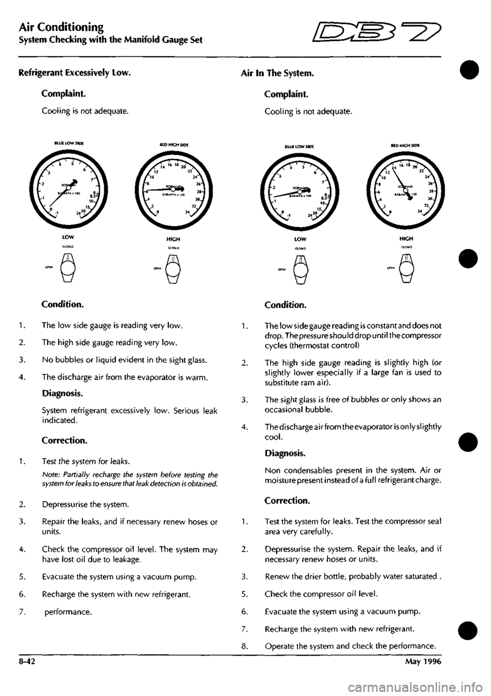
Refrigerant Excessively Low.
Complaint.
Cooling is not adequate.
Air In The System.
Complaint.
Cooling is not adequate.
BLU£ LOW SIDE SlUE LOW SIDE MD HIGH SIDE
5.
6.
7.
Condition.
1.
The low side gauge is reading very low.
2.
The high side gauge reading very low.
3. No bubbles or liquid evident in the sight glass.
4.
The discharge air from the evaporator is warm.
Diagnosis.
System refrigerant excessively low. Serious leak
indicated.
Correction.
1.
Test the system for leaks.
Note: Partially recharge the
system
before testing the
system
for
leaks
to
ensure that leak detection is
obtained.
Depressurise the system.
Repair the leaks, and if necessary renew hoses or
units.
Check the compressor oil level. The system may
have lost oil due to leakage.
Evacuate the system using a vacuum pump.
Recharge the system with new refrigerant.
performance.
2.
3.
5.
6.
7.
8-42
Condition.
The low side gauge reading
is
constant and does not
drop.
The pressure should drop until the compressor
cycles (thermostat control)
The high side gauge reading is slightly high (or
slightly lower especially if a large fan is used to
substitute ram air).
The sight glass is free of bubbles or only shows an
occasional bubble.
Thedischarge air from theevaporator
is
only slightly
cool.
Diagnosis.
Non condensables present in the system. Air or
moisturepresent instead of afullrefrigerantcharge.
Correction.
Test the system for leaks. Test the compressor seal
area very carefully.
Depressurise the system. Repair the leaks, and if
necessary renew hoses or units.
Renew the drier bottle, probably water saturated .
Check the compressor oil level.
Evacuate the system using a vacuum pump.
Recharge the system with new refrigerant.
Operate the system and check the performance.
May 1996
Page 320 of 421
^2?
Air Conditioning
System Checking with the Manifold Gauge Set
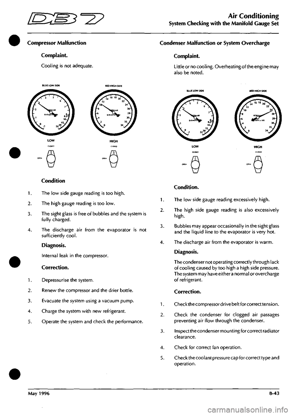
Compressor Malfunction
Complaint.
Cooling is not adequate.
Condenser Malfunction or System Overcharge
Complaint.
Little or no cooling. Overheating of the engine may
also be noted.
BLUE LOW SIDE
BLUE
LOW SIDE BED HICH SIDE
Condition
1.
The low side gauge reading is too
high.
2.
The high gauge reading is too low.
3. The sight glass is free of bubbles and the system is
fully charged.
4.
The discharge air from the evaporator is not
sufficiently
cool.
Diagnosis.
Internal leak in the compressor.
Correction.
1.
Depressurise the system.
2.
Renew the compressor and the drier bottle.
3. Evacuate the system using a vacuum pump.
4.
Charge the system with new refrigerant.
5. Operate the system and check the performance.
HIGH
Condition.
1.
The low side gauge reading excessively
high.
2.
The high side gauge reading is also excessively
high.
3. Bubbles may appear occasionally in the sight glass
and the liquid line to the evaporator is very hot.
4.
The discharge air from the evaporator is warm.
Diagnosis.
The condenser not operating correctly through lack
of cooling caused by too high a high side pressure.
The system may have either
a
normal or overcharge
of refrigerant.
Correction.
1.
Checkthecompressordrivebeltforcorrecttension.
2.
Check the condenser for clogged air passages
preventing air flow through the condenser.
3. Inspect the condenser mounting for correct radiator
clearance.
4.
Check for correct fan operation.
5. Check the coolant pressure capfor correct type and
operation.
May 1996 8-43
Page 323 of 421
Air Conditioning
System Checking with the Manifold Gauge Set ^^?
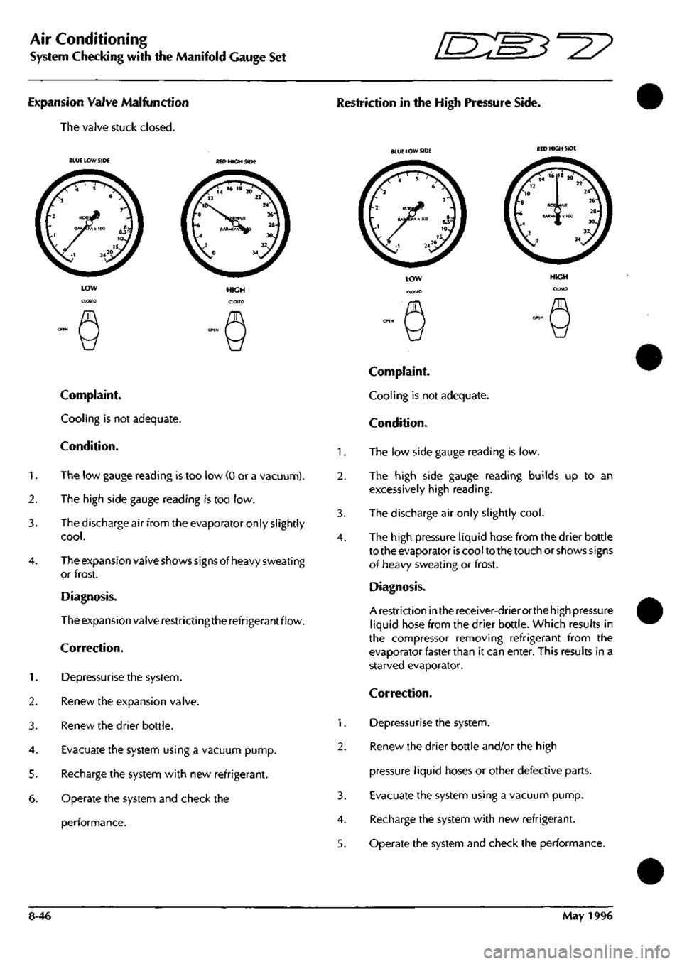
Expansion Valve Malfunction
The valve stuck closed.
Restriction in the High Pressure Side.
BLUE LOW SIDE SED HIGH SIDE
Complaint.
Cooling is not adequate.
Condition.
1.
The low gauge reading is too low (0 or a vacuunn).
2.
The high side gauge reading is too low.
3. The discharge air from the evaporator only slightly
cool.
4.
The expansion valve shows signs of heavy sweating
or frost.
Diagnosis.
The expansion valve restrictingthe refrigerant flow.
Correction.
1.
Depressurise the system.
2.
Renew the expansion valve.
3. Renew the drier bottle.
4.
Evacuate the system using a vacuum pump.
5. Recharge the system with new refrigerant.
6. Operate the system and check the
performance.
1.
2.
3.
4.
1.
2.
3.
4.
5.
BLUE LOW SIDE
Complaint.
Cooling is not adequate.
Condition.
The low side gauge reading is low.
The high side gauge reading builds up to an
excessively high reading.
The discharge air only slightly
cool.
The high pressure liquid hose from the drier bottle
to the evaporator is cool to the touch or shows signs
oi heavy sweating or frost.
Diagnosis.
A restriction in the receiver-drier orthe high pressure
liquid hose from the drier bottle. Which results in
the compressor removing refrigerant from the
evaporator faster than it can enter. This results in a
starved evaporator.
Correction.
Depressurise the system.
Renew the drier bottle and/or the high
pressure liquid hoses or other defective parts.
Evacuate the system using a vacuum pump.
Recharge the system with new refrigerant.
Operate the system and check the performance.
8-46 May 1996
Page 324 of 421
^?
Air Conditioning
Torque Settings / Depressurising the System
Torque Levels for the Hose Connections
COMPONENT TORQUE Nm
Evaporator Hose
Hose to Expansion Valve 32.0 ± 4.0
Hose to Compressor 34.0 ± 2.0
Condenser Hose
Hose to Compressor 34.0 ± 2.0
Hose to Compressor 25.0 ± 4.0
Condenser Pipe
Pipe to Drier Bottle 6.0 ± 1.5
Evaporator Pipe
Pipe to Expansion Valve 16.0 ± 1.5
Air Conditioning Procedures
Depressurising
Note:
Observe
all
safety
precautions and do not smoke
while carrying out the following
procedures.
1.
With the engine switched off, remove the protective
caps from the schraeder valves.
2.
Ensure the manifold gauge set hand valves are in
the closed position, then by using the access valve
core remover connect the manifold gauge set to the
system with the red hose to the high pressure side
and the blue hose to the low pressure side.
3. Screw out the valve core to allow the refrigerant to
flow.
4.
Place the centre hose of the manifold set into a
suitable container.
5. Slowly open the high or low side manifold hand
valve and adjust the valve for a smooth refrigerant
flow. Watch the refrigerant for any signsof escaping
oil and adjust the hand valve to prevent any oil
escaping.
6. If oil islostduringthedischarge,thecompressoroil
level must be checked and if necessary topped up.
7. As the discharge rate slows down, open the other
manifold hand valve so that refrigerant flows from
both high and low pressure sides of the system.
8. Constantly adjust the hand valves to ensure that oil
does not flow. When a zero reading is shown on
both high and low pressure gauges the system is
discharged.
8. Close both manifold hand valves.
Recovering Refrigerant
Caution: The
Recovery-Recycle-Recharging
equipment
has
special fittings to avoid
cross
contamination with
R-
12
systems.
Do not attempt to adapt
this
unit for
R-12
as
system
failure will
result.
Warning: Follow the safety procedures
as
defined at the
beginning of the section.
Caution: The unit's overfill limitation mechanism has
been
calibrated specifically for
use
with
the 50
lb.
(23 Kg)
refillable refrigerant
tank.
As the refrigerant is recovered it is passed through
an oil separator and
a
filter drier before it is allowed
to enter the refrigerant tank. When it is dry the
moisture indicator turns green.
May 1996 8-47