cooling ASTON MARTIN DB7 1997 Owner's Manual
[x] Cancel search | Manufacturer: ASTON MARTIN, Model Year: 1997, Model line: DB7, Model: ASTON MARTIN DB7 1997Pages: 421, PDF Size: 9.31 MB
Page 344 of 421
^=2?
Air Conditioning
Portable Diagnostic Unit - Signal Definitions
ThefollowingsignalsaresupportedontheAir-ConditioningControlModule. For each signal. The signal name, mnemonic
and background information are detailed.
Ambient Temperature Sensor
(AMBTEMP)
Auto-Recircuiation Input
(ARECIP)
Auto-Recirculation Output
(ARECOP)
Auxiliary Battery Positive
(AUX+)
Clutch Relay Drive Output
(CLUREL)
A/CCM Pin 34 ref Pin 6
This sensor is located in the right hand blower motor. This signal is used to enable
the A/C system to compensate for changes in ambient air temperature. The output
to pin 34 is 2.732 volts at 0 degrees Celsius and changes by 0.01 volts for each
degree Celsius above or below zero.
A/CCM Pin 9 ref Pin 6
This is effectively an On/Off switch for the A/C system and forms part of the fan
control switch.
Switch Off - Pin 9 should be at ground
Switch On - Pin 9 should be at 10+ volts.
When pin 9 is at ground, pin 3 will be at 10+ volts causing the recirculation flaps
to open.
A/CCM Pin 3 ref Pin 6
This signal will cause the recirculation flaps to close. Operating conditions should
be:
A/C Off - 10+ volts at pin 3, flaps open.
Temp demand minimum - 10+ volts at pin 3, flaps open.
Defrost - 0 volts at pin 3, flaps closed.
Temp demand max - 0 volts at pin 3, flaps closed.
A/CCM Pin 1 ref Vehicle Battery -ve
This signal istheauxiliary supply to the A/CCM. Pin
1
should read battery voltage
if the ignition switch is in the auxiliary or ignition on positions. Pin
1
should read
0 volts when the ignition switch is in the Off position or in position III whilst
cranking the engine. Loss of this supply will cause total failureof the A/C system.
A/CCM Pin 20 ref Pin 6
This signal responds to the input at pin 5 (evaporator sensor). When pin 5 is
between 2.715 and 2.725 volts, pin 20 should read below 1 volt, and the
compressor clutch will be switched off. When pin 5 is between 2.735 and 2.745
volts,
pin 20 will rise to 10+ volts and the compressor will re-engage.
Centre Vent Solenoid
(CVSOL) A/CCM Pin 18 ref Pin 6
The centre vent solenoid controls the operation of the centre vent flap. The centre
vent will open to increase the cooling capabilities of the vehicle when cooling is
selected.
In all other conditions, the centre vent will be closed.
Solenoid energised: pin 18 should read 10+volts and the centre vent will be open.
Solenoid de-energised; pin 18 should read below 0.5 volts and the centre vent
should be closed.
May 1996 8-67
Page 346 of 421
3^7?
Air Conditioning
Portable Diagnostic Unit - Signal Definitions
Fanspeed Medium
(FANMED)
Five Volt Supply
(FIVEV)
Flap Servo Drive Signals
Lower Servo Forward Drive
(FORSERL)
Upper Servo Forward Drive
(FORSERU)
Lower Servo Reverse Drive
(REVSERL)
Upper Servo Reverse Drive
(REVSERU)
Ground Voltage
(GND10)
A/CCMPin 14ref Pin6
This signal is generated from the fanspeed control switch.
Switch at Low, pin 14 should read 0.6 volts.
Switch at Off, L, H or D positions, pin 14 should read 3.6 ±0.8 volts.
A/CCM Pin 43 ref Pin 6
This 5 volt rail provides the power supply for all the sensors and the feedback
potentiometers. Any variation in this signal would totally upset the balance of the
whole system.
The servo drive signals control the position of the upper and lower
flaps.
The drive
signals work in pairs, two for the upper and two for the lower flaps.
A/CCM Pin 37 ref Pin 6
A/CCM Pin 40 ref Pin 6
A/CCM Pin 41 ref Pin 6
A/CCM Pin 42 ref Pin 6
When the flaps are stationary, all signals will be at 0.6 volts approximately. When
the flap(s) is being driven, the drive iine(s) will rise to approximately 6 volts.
As the flap approaches its final position, the drive signal will be pulsed to nudge
the flap to the exact position required.
Note: If
a
drive
signal rises to above
8.5
volts
and
the servo
motor
does
not
operate,
suspect
an open circuit within the servo.
A/CCM Pin 10 ref Pin 6
This is the ground supply from the A/CCM to the in-car sensor and should read
below 10 millivolts.
Failure of this line will cause the in-car sensor to believe the vehicle temperature
to be at maximum all the time, thus forcing the system into permanent cooling.
Under these circumstances, pin 4 (in-car sensor output) will be approximately 5
volts.
May 1996 8-69
Page 350 of 421
O" D'^?
Air Conditioning
Portable Diagnostic Unit - Signal Definitions
Reference Signal
(REF) A/CCM Pin 7 ref Pin 6
This is the main reference signal for the A/CCM. All the sensors reference against
this voltage. Drift in this signal will cause inconsistent temperature control.
Normal voltage should read 2.885 ±10 millivolts
Temperature Demand
(TEMPDEM)
Temperature demand control either selects the required temperature of the system
(auto mode) or the outlet temperature of the vents (manual mode). Pin 35 will vary
from 0 volts at full cooling up to 2.885 volts at full heating.
Note: When
defrost is
selected,
the
signal at pin 35
is
ignored.
The system
will go into full
heating through the upper flaps
only.
Upper Servo Feedback Potentiometer
(USERFB) A/CCM Pin 30 ref Pin 6
The feedback signal informs the control module ofthe exact position of the flaps,
enabling accurate control ofthe flap position.
Defrost - Lower flap signal should read 2.9 volts (flap closed, the upper flap
signal should read 1.9 volts.
Max Temperature - Lower flap signal should read 1.14 volts, upper flap signal
should read 1.9 volts.
Min Temperature - Both upper and lower flap signals should read
1
30 ±80
millivolts.
Note: If the
feedback sticks
low, with the
fan
continually running,
suspect an
open circuit
in the 5 volt supply to the feedback potentiometer or the potentiometer itself
Water Switch
(WATSW)
Water Valve
(WATVAL)
A/CCM Pin 21 ref Pin 6
The water switch monitors the temperature ofthe coolant and inhibits heating by
restricting fan operation at coolant temperatures below 30 degrees Celsius. This
enables the vehicle to warm up at a faster rate. It can be overridden by selecting
Defrost.
A/CCM Pin
1
7 ref Pin 6
The water valve controls thef low of hot coolant to the heater matrix. When manual
full cooling is selected, the valve will close inhibiting the heating effort ofthe
matrix, thus enhancing the cooling effect
Full cooling selected; pin
1
7 should read 10+volts and the water valve should be
closed.
All other conditions, pin
1
7 should read below 0.5 volts and the water valve should
be open.
May 1996 8-73
Page 359 of 421
The Aston Martin Lagonda Diagnostic System
Installation Instructions ^7
Base Station installation
It is recommended that the base station is wall
mounted (Fig 3). Alternatively it may be mounted
on a bench. The base station houses the CD-ROM
drive and power supplies.
Note: The electronic module should only be fitted
after
the base station has been installed.
Wall Mounting
It
is
importantthatthefollowing points be considered
before carrying out the mounting procedure.
The location should be close to the vehicle repair
bays.
The base station will require a power outlet
close by, such that the 2m mains lead will
comfortably reach the outlet.
Thewall plate should be attached with fourfasteners,
each of which has a minimum pull-out strength of
300 kg (662 lb). Thefourfasteners are not supplied,
as the type of fastening will depend on the wall
material.
The mounting holes in the wall plate are
8mm diameter with a maximum clearance for a
socket spanner of 30mm. It is recommended that
6mm diameter bolts are used to secure the wall
plate.
WARNING: The mains power outlet must be dose
to the equipment and be clearly recognisable as
the power source for safety reasons.
French Market
Only:
Do not connect the PDU
equipment
to
IT(lmpedante Terre) power systems.
r
900mm
Figure 3. Wall Mounted installation
WARNING: This equipment must be earthed via
the
mains
lead through the outlet socket. In markets
where three pin main power outlets are not
available, a separate earth point must be used
Procedure
1.
Select a suitable location.
2.
Mark a horizontal line on the wall 900mm above
the floor (Fig 3)
3. Removethetwoscrewssecuringthewall mounting
plate to the base station and remove the wall
mounting plate.
4.
Holdthewall mounting plate up to the marked line
and mark four hole positions for the wall mounting
plate bolts.
5. Drill the wall to the correct diameter and depth
required for the four bolts.
6. Securely fasten the wall mounting plate to the
wall.
Lift the base station onto the wall mounting plate,
fit and tighten the two screws/washers to secure the
base station to the mounting plate.
CAUTION: The gap beneath the base station
should be maintained free from obstructions to
allow a flow of air under the unit for cooling.
9-8 May 1996
Page 360 of 421
^^?
The Aston Martin Lagonda Diagnostic System
I nstal lation I nstructions
Bench Mounting
The base station may also be mounted on a bench, which
must be in a safe position, stable and protected form
hazards and impacts. The base station must be mounted
at the back of the bench. 'Z' clips are provided for
permanent mounting. The bench surface must be kept free
from dust at all times.
CAUTION:
A gap under the base station must be
maintained free from obstructions to allow a flow of air
under the unit for cooling.
Electronic Module installation
WARNING: The base station electronic module must be
disconnected from the mains supply prior to installation/
removal from the base station assembly. DO NOT
reconnect to the mains supply until the module is safely
fitted into the base station. This unit must be earthed.
Note:
Users in North America are advised to replace the
ceramic mains fuse in the electronic module with theglass
fuse supplied.
Procedure
1.
Unlock the base station door
2.
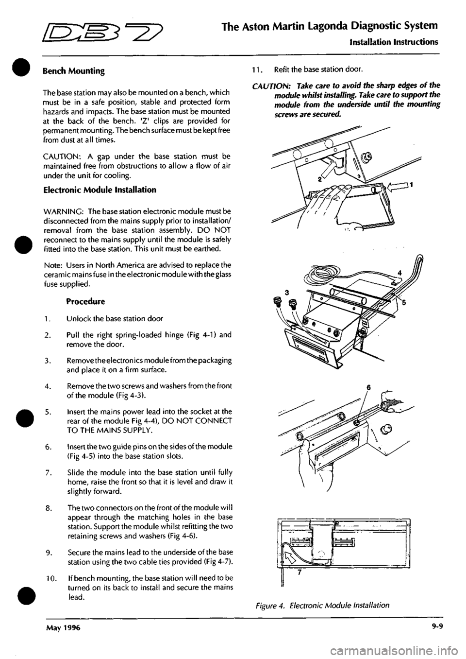
Pull the right spring-loaded hinge (Fig 4-1) and
remove the door.
3. Removetheelectronicsmodulefrom the packaging
and place it on a firm surface.
4.
Remove the two screws and washers from the front
of the module (Fig 4-3).
5. Insert the mains power lead into the socket at the
rear of the module Fig 4-4), DO NOT CONNECT
TO THE MAINS SUPPLY.
6. Insert the two guide pins on the sides of the module
(Fig 4-5) into the base station slots.
7. Slide the module into the base station until fully
home,
raise the front so that it is level and draw it
slightly forward.
8. The two connectors on the front of the module will
appear through the matching holes in the base
station.
Support the module whilst refitting the two
retaining screws and washers (Fig 4-6).
9. Secure the mains lead to the underside of the base
station using the two cable ties provided (Fig 4-7).
10.
If bench mounting, the base station will need to be
turned on its back to install and secure the mains
lead.
11.
Refit the base station door.
CAUTION: Take care to avoid the sharp edges of the
module whilst installing. Take care to support the
module from the underside until the mounting
screws are secured.
Figure 4. Electronic Module Installation
May 1996 9-9
Page 386 of 421
^^2?
The Aston Martin Lagonda Diagnostic System
Users Guide
Output State Control - 97 MY
This menu item provides a quick test of the basic electro
mechanical components controlled by the PCM. These
tests should be performed in a key on engine off state.
The selections available are:
• Low Speed Cooling Fans
• High Speed Cooling Fans
• Set Electromechanical Outputs
Low and High Speed Fans
Selecting and confirming either the low or high speed
cooling fans will run the fans at the selected speed for 5
seconds to verify their operation.
Electromechanical Outputs
This selection will cause the following electromechanical
devices to operate for five seconds
Air Pump
Fuel Pumps
Canister Purge Valve
Idle Air Control Valve
Observing each device in turn as the PCM outputs are
turned 'On' will enable the technician to verify correct
operation.
September 1996 9-35
Page 392 of 421
^^?
The Aston Martin Lagonda Diagnostic System
Users Guide
Transmission Diagnostics
Selecting 'Transmission from the vehicle area menu will
present the technician with the following transmission
diagnostic tools menu:
Transmission Diagnostic
• Datalogger
• Diagnostic Trouble Codes
o
The Datalogger function is fully described in the worked
example at the rear of this PDU Users Guide.
Transmission Datalogger
The PDU datalogger function may be used to monitor the
following transmission controller signals
DIGS Number of DTCs Logged
The Diagnostics status manager (DSM) receives and
processes fault information and decides when a DTC
should be logged and the MIL turned on (if enabled). The
actual total stored is indicated by the parameter DTCS.
FBRAKE Brake Switch
The footbrake switch signal is input to the
TCM.
The input
is normally at ground potential and goes open circuit
when the brakes are applied. If the torque converter
clutch is applied it will disengage when this signal is
detected.
FMA Actual Force Motor Current
The force motor regulates the transmission fluid pressure.
It is a variable force solenoid whose coil current is
determined by the TCM. Range 0 -1.245 amps. A driver
circuit limits excessive current flow and performs a
ratiometric comparison of Desired (commanded) Force
Motor Current and Actual Force Motor current. The
parameter monitors the Actual Force Motor current 1 Bit
= l/204.8amps.
HOT Hot Mode
The signal from the transmission temperature sensor is
used to control TCC and line pressure. It is also used in
many diagnostic signals and is a critical component for
OBD II. Above 120°C the TCC is on in 2nd, 3rd and 4th
gears.
This reduces transmission temperature by decreasing
the heat generated by the torque converter. It also
provides maximum cooling by routing transmission fluid
directly to the transmission cooler in the radiator. When
the Hot Mode is ON the bit is set to 1.
IGN+ Ignition Feed Positive
The TCM receives ignition voltage through TCM pin 53.
MD Desired Force Motor Current
The force motor regulates the transmission fluid pressure.
It is a variable force solenoid whose coil current is
determined by the TCM. Range 0 -1.245 amps. A driver
circuit limits excessive current flow and performs a
ratiometric comparison of Desired (commanded) Force
Motor Current. The parameter mon itors the Desired Force
Motor current 1 Bit = 1/204.8amps.
RATIO Actual Gear Ratio
The diagnostic detects malfunction in the transmission
output components by monitoring the actual gear ratio.
The actual gear ratio is calculated using input (Ni) and
output speed (No): Ratio = Ni/No. This is compared with
the standard gear ratio for each gear. Malfunction can be
defined as: actual gear ratio is not equal to any of the
standard gear ratios.
RPM Engine Speed
The engine speed signal is input from the instrument pack.
The
signal
origi
nates
at the crankshaft
sensor.
The crankshaft
sensor signal is modified by the PCM and the instrument
pack before being input to the TCM.
SSA Shift Solenoid A
Shift solenoid A is attached to the valve body and its outlet
is open to exhaust when it is switched off. A OFF - outlet
open - 2nd and 3rd gears selected. The solenoid is
energised by the TCM providing an internal ground to
close the outlet. A ON - outlet closed -1 st and 4th gears
selected.
SSB Shift Solenoid B
Shift solenoid B is attached to the valve body and its outlet
is open to exhaust when it is switched off. B OFF - outlet
open - 1st and 2nd gears selected. The solenoid is
energised by the TCM providing an internal ground to
close the outlet. B ON - outlet closed - 3rd and 4th gears
selected.
September 1996 9-41
Page 405 of 421
The Aston Martin Lagonda Diagnostic System
Users Guide
•=2?
Clear all Trouble Codes
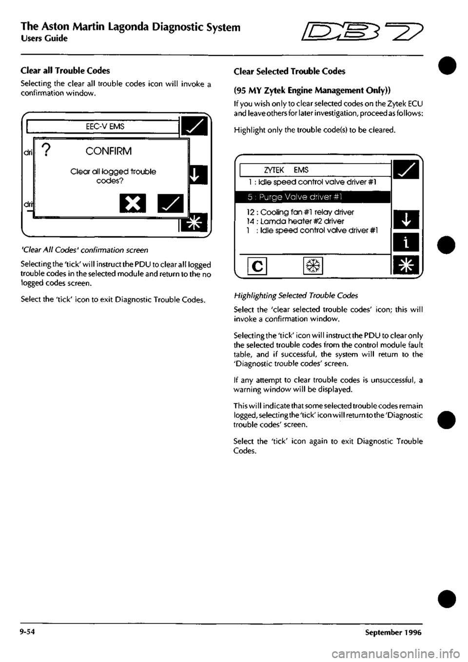
Selecting the clear all trouble codes icon will invoke a
confirmation window.
EEC-V EMS
dri
dri
CONFIRM
Clear all logged trouble
codes?
O
'Clear
All Codes' confirmation
screen
Selectingthe'tick'will instructthePDU to clear all logged
trouble codes in the selected module
and
return to the no
logged codes screen.
Select the 'tick' icon to exit Diagnostic Trouble Codes.
Clear Selected Trouble Codes
(95 MY Zytek Engine Management Only))
If
you
wish only to clear selected codes on the Zytek ECU
and
leave others
for later
investigation,
proceed
as
follows:
Highlight only the trouble code(s) to be cleared.
ZYTEK EMS
1 : Idle speed control valve driver #1
5 : Purge Valve driver #1
12 : Cooling fan#l relay driver
14 : Lannda heater
#2
driver
1 : Idle speed control valve driver #1
Highlighting
Selected
Trouble
Codes
Select the 'clear selected trouble codes'
icon;
this will
invoke a confirmation window.
Selectingthe 'tick' icon will instruct
the
PDU to clear only
the selected trouble codes from the control module fault
table,
and if successful, the system will return to the
'Diagnostic trouble codes' screen.
If any attempt to clear trouble codes is unsuccessful, a
warning window will be displayed.
This will indicatethat
some selected
trouble codes remain
logged,selectingthe'tick'iconwillreturntothe'Diagnostic
trouble codes' screen.
Select the 'tick' icon again to exit Diagnostic Trouble
Codes.
9-54 September 1996