heater ASTON MARTIN DB7 1997 Owner's Manual
[x] Cancel search | Manufacturer: ASTON MARTIN, Model Year: 1997, Model line: DB7, Model: ASTON MARTIN DB7 1997Pages: 421, PDF Size: 9.31 MB
Page 274 of 421
^?
Body and Trim
Cheater Panel Seals
9.2.01.7
Renew
Cheater Plate Seals - Adjust/
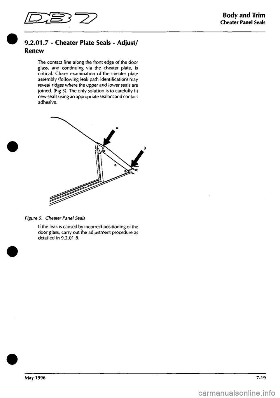
The contact line along the front edge of the door
glass,
and continuing via the cheater plate, is
critical.
Closer examination of the cheater plate
assembly (following leak path identification) may
reveal ridges where the upper and lower seals are
joined.
(Fig 5). The only solution is to carefully fit
new
seals using an
appropriate sealant
and
contact
adhesive.
Figure
5.
Cheater Panel Seals
If the leak is caused by incorrect positioning of the
door glass, carry out the adjustment procedure as
detailed in 9.2.01.8.
May 1996 7-19
Page 280 of 421
^7
Air Conditioning
Contents
Repair Procedures
8.1.01.1 Compressor Removal/Renewal 8-51
8.1.02.1 Field Coil Renewal 8-52
8.1.03.1 Renew Gasket Kit 8-52
8.1.04.1 Valve Plate Renewal 8-53
8.1.05.1 Expansion Valve Renewal 8-54
8.1.06.1 Hose-Compressor to Evaporator Renewal 8-55
8.2.01.1 Air Conditioning Unit Renewal 8-55
8.2.02.1 Evaporator Unit Renewal 8-56
8.2.03.1 Upper Servo Feedback Potentiometer Renewal 8-57
8.2.04.1 Lower Servo Feedback Potentiometer Renew 8-57
8.2.05.1 Upper Flap Motor Assembly Renew 8-58
8.2.06.1 Lower Flap Motor Assembly Renew 8-58
8.2.07.1 Ambient Temperature Sensor Renew 8-59
8.2.08.1 Blower Motor Driver Side Renewal 8-59
8.2.09.1 Blower Motor Passenger Side Renewal 8-59
8.2.10.1 Blower Assembly Driver/Passenger Side Overhaul 8-60
8.2.11.1 Blower Motor High Speed Relay Renewal 8-61
8.2.12.1 Water Temperature Switch Renewal 8-62
8.2.13.1 Heater Matrix Renewal 8-62
8.2.14.1 Electronic Control Module Renew 8-63
8.3.01.1 Vacuum System Solenoid Renewal 8-63
May 1996 8-3
Page 284 of 421

^^?
Air Conditioning
System Description
System Description
The in-car temperature and humidity are regulated by the electronically controlled air conditioning system. The
system comprises four subsystems:
• heater matrix, supplied with water from the engine cooling system
• refrigeration
• vacuum
• electronic control
Apart from the ambient temperature sensor and the aspirated in-car temperature sensor, most of the components
are housed in the air conditioning unit (Fig. 1) situated behind the dash board, or in the engine compartment.
Figure 1.
Key to Fig. 1 - Left Hand Air Conditioning Unit
1.
Upper feedback potentiometer
2.
Water temperature switch
3. Lower feedback potentiometer
4.
Vacuum valve block
5. Vacuum restrictor
6. Condensate drain tube
Figure 2.
Key to Fig. 2 - Right Hand Air Conditioning Unit
1.
Upper servo motor
2.
Electronic control module
3. Lower servo motor
4.
Evaporator sensor
5. Condensate drain tube
Special Servicing Tools and Equipment
1 PDU system
1 Charging station
1 Leak detector
1 Temperature test box
1 Sanden compressor service tool kit
1 CM Type compressor service tool kit
1 Digital voltmeter
1 Multimeter
May 1996 8-7
Page 286 of 421
^7
Air Conditioning
Temperature Distribution System
Temperature Distribution System
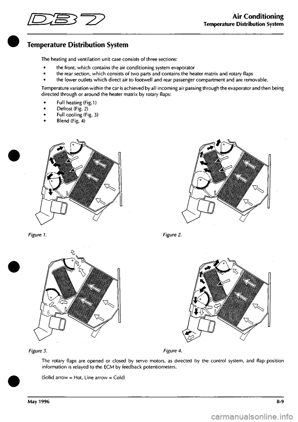
The heating and ventilation unit case consists of three sections:
• the front, which contains the air conditioning system evaporator
• the rear section, which consists of two parts and contains the heater matrix and rotary flaps
• the lower outlets which direct air to footwell and rear passenger compartment and are removable.
Temperature variation within the car
is
achieved by all incoming air passing through the evaporator and then being
directed through or around the heater matrix by rotary flaps:
• Full heating (Fig.1)
• Defrost (Fig. 2)
• Full cooling (Fig. 3)
Blend (Fig. 4)
Figure 1.
Figure
2.
Figure
3.
Figure
4.
The rotary flaps are opened or closed by servo motors, as directed by the control system, and flap position
information is relayed to the ECM by feedback potentiometers.
(Solid arrow = Hot, Line arrow = Cold)
May 1996 8-9
Page 296 of 421
^2?
Air Conditioning
Electronic Control Module
Electronic Control Module (ECM)
The Electronic Control Module (ECM) is located on the right hand side of the heater unit.
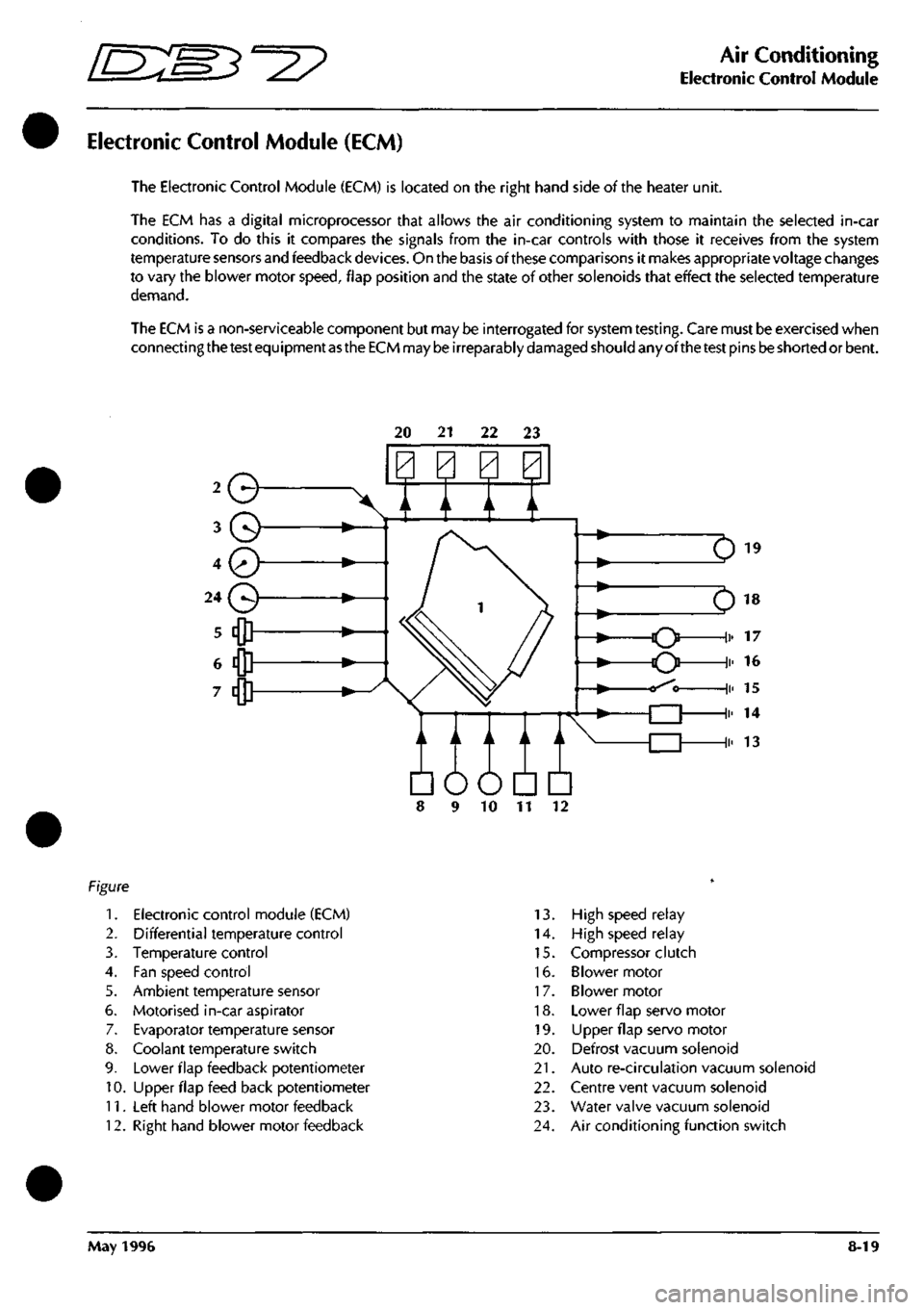
The ECM has a digital microprocessor that allows the air conditioning system to maintain the selected in-car
conditions. To do this it compares the signals from the in-car controls with those it receives from the system
temperature sensors and feedback
devices.
On the basis of these comparisons it makes appropriate voltage changes
to vary the blower motor
speed,
flap position and the state of other solenoids that effect the selected temperature
demand.
The ECM is a non-serviceable component but may be interrogated for system
testing.
Care must be exercised when
connecting
the test
equipment
as the ECM
may
be
irreparably
damaged
should any ofthe
test
pins
be
shorted or bent.
20 21 22 23
Q
A / A \/
Em
10 11
1.
Electronic control module (ECM)
2.
Differential temperature control
3. Temperature control
4.
Fan speed control
5. Ambient temperature sensor
6. Motorised in-car aspirator
7. Evaporator temperature sensor
8. Coolant temperature switch
9. Lower flap feedback potentiometer
10.
Upper flap feed back potentiometer
11.
Left hand blower motor feedback
12.
Right hand blower motor feedback
13.
High speed relay
14.
High speed relay
15.
Compressor clutch
16.
Blower motor
17.
Blower motor
18.
Lower flap servo motor
19.
LIpper flap servo motor
20.
Defrost vacuum solenoid
21.
Auto re-circulation vacuum solenoid
22.
Centre vent vacuum solenoid
23.
Water valve vacuum solenoid
24.
Air conditioning function switch
May 1996 8-19
Page 302 of 421
•=2?
Air Conditioning
Water Temperature Switch / Blower Motors
Water Temperature Switch
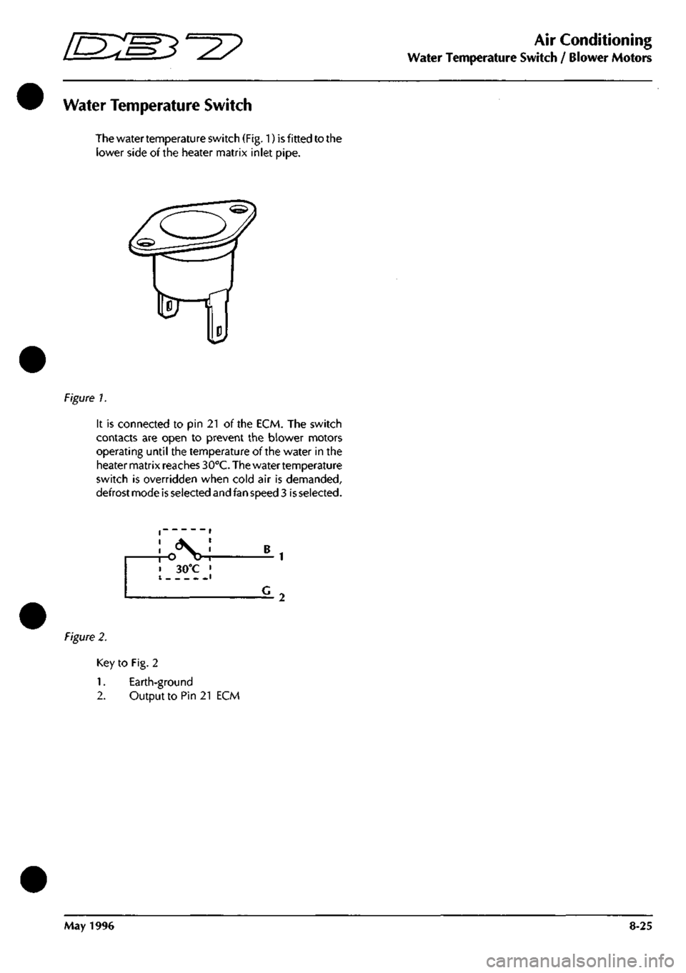
The water temperature switch (Fig. 1) is fitted to the
lower side of the heater matrix inlet pipe.
Figure 7.
It is connected to pin 21 of the ECM. The switch
contacts are open to prevent the blower motors
operating until the temperature of the water in the
heater matrix reaches 30°C. The water temperature
switch is overridden when cold air is demanded,
defrost mode is selected and fan speed 3
is
selected.
Figure 2.
Key to Fig. 2
1.
Earth-ground
2.
Output to Pin 21 ECM
May 1996 8-25
Page 305 of 421
Air Conditioning
Vacuum System •^^
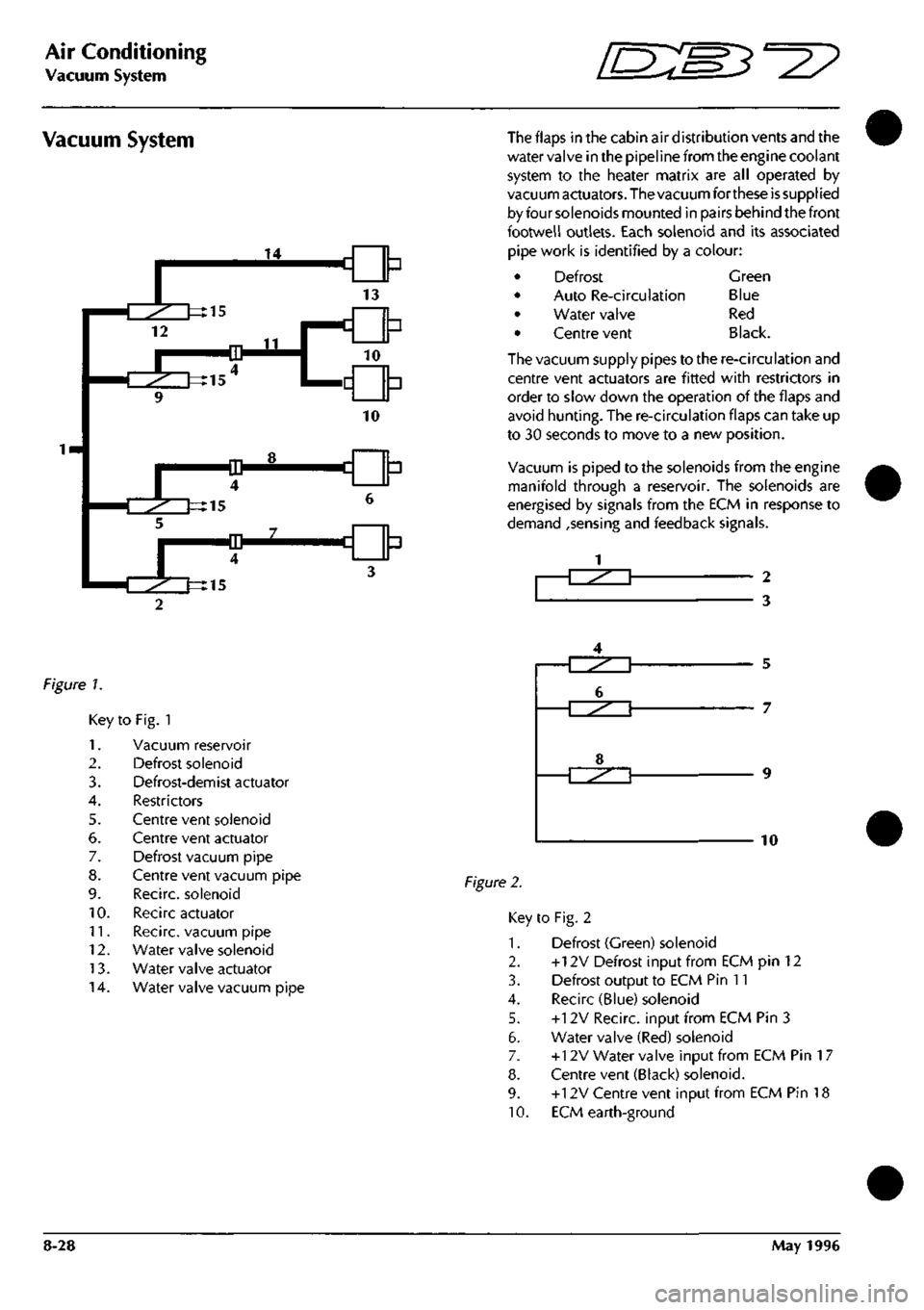
Vacuum System The flaps in the cabin air distribution vents and the
water valve in the pipeline from the engine coolant
system to the heater matrix are all operated by
vacuum actuators. The vacuum forthese
is
supplied
by four solenoids mounted in pairs behind the front
footwell outlets. Each solenoid and its associated
pipe work is identified by a colour:
Defrost
Auto Re-circulation
Water valve
Centre vent
Green
Blue
Red
Black.
The vacuum supply pipes to the re-circulation and
centre vent actuators are fitted with restrictors in
order to slow down the operation of the flaps and
avoid hunting. The re-circulation flaps can take up
to 30 seconds to move to a new position.
Vacuum is piped to the solenoids from the engine
manifold through a reservoir. The solenoids are
energised by signals from the ECM in response to
demand ,sensing and feedback signals.
-T^^^T 2
3
figure 7.
Key
1.
2.
3.
4.
5.
6.
7.
8.
9.
10.
11.
12.
13.
14.
to Fig. 1
Vacuum reservoir
Defrost solenoid
Defrost-demist actuator
Restrictors
Centre vent solenoid
Centre vent actuator
Defrost vacuum pipe
Centre vent vacuum pipe
Recirc. solenoid
Recirc actuator
Recirc. vacuum pipe
Water valve solenoid
Water valve actuator
Water valve vacuum pipe
Figure 2.
5
7
10
Key to Fig. 2
1.
Defrost (Green) solenoid
2.
+12V Defrost Input from ECM pin 12
3. Defrost output to ECM Pin 11
4.
Recirc (Blue) solenoid
5. +12V Recirc. input from ECM Pin 3
6. Water valve (Red) solenoid
7. +12V Water valve input from ECM Pin
1
7
8. Centre vent (Black) solenoid.
9. +12V Centre vent input from ECM Pin 18
10.
ECM earth-ground
8-28 May 1996
Page 332 of 421
^2?
Air Conditioning Repair Procedures
Hose - Compressor to Evaporator/Air-Con Unit Renew
8.1.06.1 Hose-Compressor
to
Evaporator
Renewal
Procedure
1.
Open the bonnet and fit a wing cover.
2.
Depressurise the air conditioning systenn.
3. Remove the hose to evaporator valve clamping
plate,
disconnect the hose from the valve, remove
and discard the 'O' ring
seal.
4.
Fit a blanking plug to the evaporator valve. Release
the evaporator hose securing clips.
5. Remove the compressor outlet port retaining bolt.
6. Disconnect the hose from the compressor, discard
the hose complete with 'O' ring seals.
7. Connect the hose to the evaporator valve and
tighten clamp onto the hose.
8. Route the hose to the compressor, fit a new 'O' ring
seal and connect it to the compressor.
9. Position the outlet port retaining plate on the
compressor, fit and tighten the securing bolt.
10.
Refit the hose to the clips.
11.
Charge the air conditioning system.
12.
Remove the wing cover and close the bonnet.
8.2.01.1 Air Conditioning Unit Renewal
1.
Disconnect the battery earth
lead.
2.
Drain the engine coolant into a suitable container.
3. Depressurise the air conditioning system.
4.
Disconnect the high and low pressure hoses and
expansion valve from the air conditioning unit (see
expansion valve renewal).
5. Slacken the coolant hose to the heater matrix pipe
securing clips and disconnect the hoses from the
matrix. (This will require the removal of the air
intake hose for access.)
6. Remove the following items from inside the car:
front seats
underscuttle panels/knee bolsters
glove box assembly
facia trim (walnut trim)
radio and ashtray
centre console switch panel assembly
instrument panel and surround trim
steering wheel and column
facia assembly complete
hoses - distribution box to door vents
facia support frame
Details and drawings of the above operations can
be found in the electrical and trim sections.
Disconnect the vacuum hoses from the blower
motors, water valve and reservoir.
Un-clip the electrical harness from the air
conditioningunit, release theelectrical connections
and reposition the harness to allow removal of the
unit.
Displace and remove the footwell ventilator ducts
and hoses (Fig. 1-1).
May 1996 8-55
Page 333 of 421
Air Conditioning Repair Procedures
Air-Conditioning Unit Renew ^^?
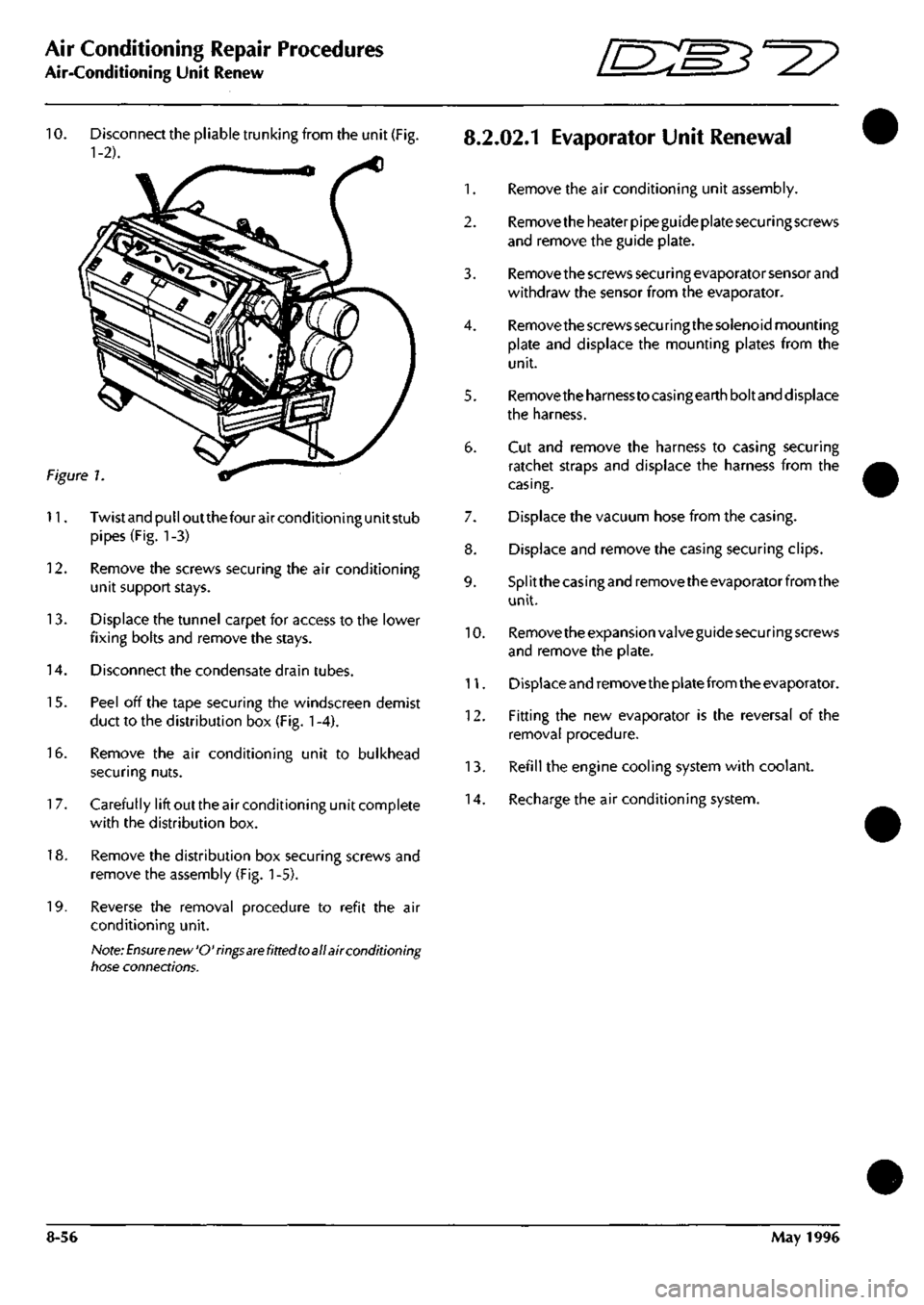
10.
Disconnect the pliable trunking from the unit (Fig.
8.2.02.1
EvaporatOr Unit Renewal
1-2). ^
1.
Remove the air conditioning unit assembly.
2.
Remove the heater pipe guide plate securing screws
and remove the guide plate.
3. Remove the screws secu ri ng evaporator sensor and
withdraw the sensor from the evaporator.
4.
Remove the screws securing the solenoid mounting
plate and displace the mounting plates from the
unit.
5. Removetheharnesstocasingearthboltand displace
the harness.
6. Cut and remove the harness to casing securing
ratchet straps and displace the harness from the
casing.
7. Displace the vacuum hose from the casing.
8. Displace and remove the casing securing clips.
9. Splitthecasingandremovetheevaporatorfromthe
unit.
10.
Remove the expansion valve guide securing screws
and remove the plate.
11.
Displace and remove the plate from the evaporator.
12.
Fitting the new evaporator is the reversal of the
removal procedure.
13.
Refill the engine cooling system with coolant.
14.
Recharge the air conditioning system.
Figure 1
11.
Twistandpulloutthefourairconditioningunitstub
pipes (Fig. 1-3)
12.
Remove the screws securing the air conditioning
unit support stays.
13.
Displace the tunnel carpet for access to the lower
fixing bolts and remove the stays.
14.
Disconnect the condensate drain tubes.
15.
Peel off the tape securing the windscreen demist
duct to the distribution box (Fig.
1
-4).
16.
Remove the air conditioning unit to bulkhead
securing nuts.
1
7. Carefully lift out the air conditioning unit complete
with the distribution box.
18.
Remove the distribution box securing screws and
remove the assembly (Fig.
1
-5).
19.
Reverse the removal procedure to refit the air
conditioning unit.
Note:
Ensure new'O'rings
are
fitted toall air conditioning
tiose connections.
8-56 May 1996
Page 339 of 421
Air Conditioning Repair Procedures
Water Temperature Switch/Heater Matrix Renew •=2?
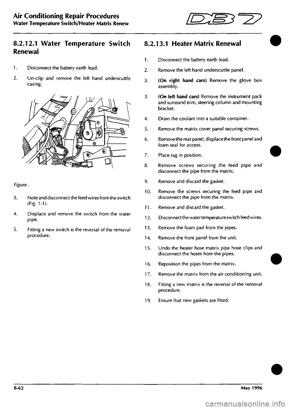
8.2.12.1 Water Temperature Switch
Renewal
1.
Disconnect the battery earth
lead.
2.
Un-clip and remove the left hand underscuttle
casing.
Figure.
3. Note and disconnect the feed wires from the switch
(Fig.
1-1).
4.
Displace and remove the switch from the water
pipe.
5. Fitting a new switch is the reversal of the removal
procedure.
8.2.13.1 Heater Matrix Renewal
1.
Disconnect the battery earth
lead.
2.
Remove the left hand underscuttle panel.
3. (On right hand cars) Remove the glove box
assembly.
3. (On left hand cars) Remove the instrument pack
and surround
trim,
steering column and mounting
bracket.
4.
Drain the coolant into a suitable container.
5. Remove the matrix cover panel securing screws.
6. Removethe rear
panel,
displacethefront panel and
foam seal for access.
7. Place rag in position.
8. Remove screws securing the feed pipe and
disconnect the pipe from the matrix.
9. Remove and discard the gasket.
10.
Remove the screws securing the feed pipe and
disconnect the pipe from the matrix.
11.
Remove and discard the gasket.
12.
Disconnectthewatertemperatureswitchfeedwires.
13.
Remove the foam pad from the pipes.
14.
Remove the front panel from the unit.
15.
Undo the heater hose matrix pipe hose clips and
disconnect the hoses from the pipes.
16.
Reposition the pipes from the matrix.
1
7. Remove the matrix from the air conditioning unit.
18.
Fitting a new matrix is the reversal of the removal
procedure.
19.
Ensure that new gaskets are fitted.
8-62 May 1996