heater ASTON MARTIN DB7 1997 User Guide
[x] Cancel search | Manufacturer: ASTON MARTIN, Model Year: 1997, Model line: DB7, Model: ASTON MARTIN DB7 1997Pages: 421, PDF Size: 9.31 MB
Page 180 of 421

NO
COLOUR
ms 8
909
NG
999
BK
2160
B
995
NK
PIN
1 ? i 4
5
7
S 9 10 tl 12
AREA
A3
86
06
A3 86
RQ
SEAT HEATER
SWITC
NO
COLOUf
2155
R
749
OU
2161
0
2162
OR
2159
B
996
P
2163
KR
2164
K
2165
S
2166
SN
362
RW
i
PAC
PIN 1 2 3 4 5 6 / e
9 10 II 12 13
14
K
AREA B4-2I5
06 01 01 A3 86 Dl 01 01
01
86
NO
2157
?l5fl
2159 2160
COLOUR
B B B B
AREA
A4 Al 81 Al
NO
COLOUR
PIN
2157
8 1
2154
R 2 J 4
AREA
A3
84-215
NO
COLOUR
998
WK
2166
SN
2165
S
2162
OR
2164
K
2163
KR
997
BP
2161
0
PIN 1 4 B 9 1? 13 ?8 37
AREA
86 CI 81 81 81 81 86 ei
c/a
24 48
NO
COLOUf
995 NK
362
RW
996 PN
909 NG 997 8S 998 WK 904 OW 750 OS 749
OU
999 8K
PIN
1 2 3 4
5
6 7
8 9 10 II 12 13
14 15 16
AREA
Al
CI Bl
Al Dl 01
C3-2I4
03 81 Al
SHEET 12 AREA D6
NO
COLOUR
750
OS
2156
OW
2157
R
2158
OW
PIN 85 RR
87 87A
30
AREA
C6
C4-2I4 84-215
C4-2I4
HEATER RELAY
'"^P Wiring Diagram
Model - Aston Martin DB7
Harness Title - Passengers Sill
Part No. - B37-84649
Revision - 0 Sheet 24 of 26 - 97 MY
Page 184 of 421
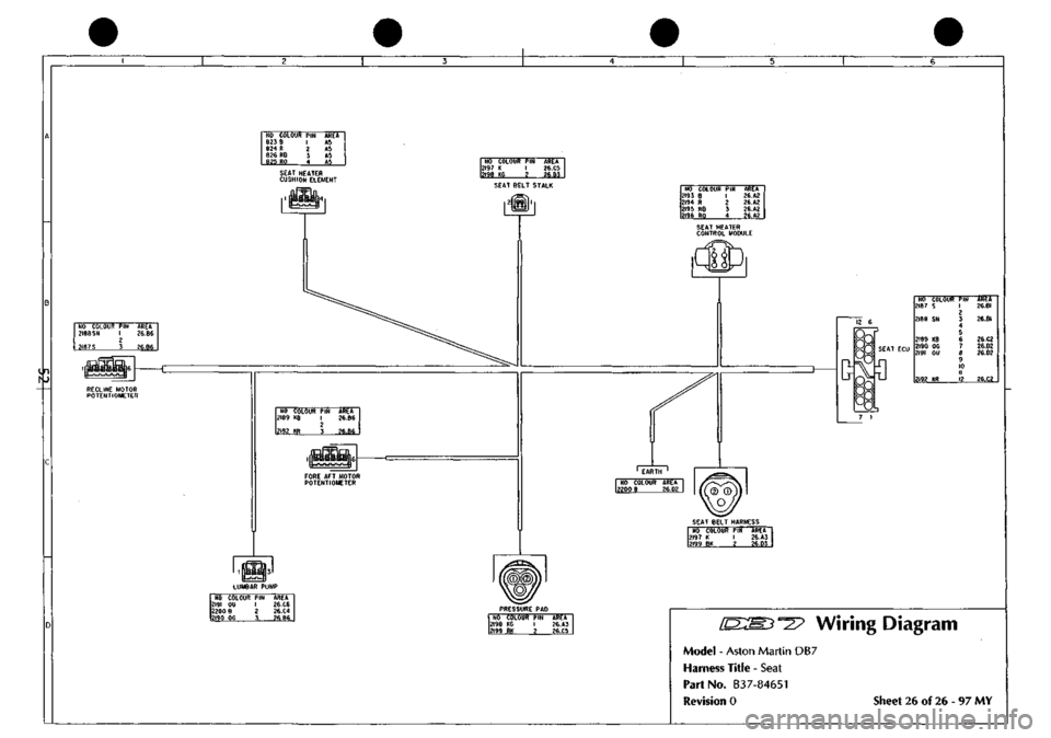
NO COLOUR
PIN
823
8 1
824
R
2
826 RB
3
825 RO
4
AREA
A5 A5 A5 AS
SEAT HEATER
CUSHION
ELEMENT
NO COLOUR
PIN
2193
e 1
2194
R 2
2195
RB 3
2196
RO 4
AREA 26.A2 26.A2 26.A2 26.A2
in
NO COLOUR
PIN
AREA 2188
SN
1
26.B6 2 2187
S
3
26.B6
16
NO COLOUf 2187
S
2186
SN
2189
KB
2190
OG
2191
OU
2192
KR
PIN
1 ? 3 4 S
6 1
e
9 10 11
12
AREA 26.BI
26.BI
2e.C2 26.D2 26.02
26.02 RECLINE MOTOR POTENTIOMETER
Wiring Diagram
Model - Aston Martin DB7
Harness Title - Seat
Part No. B37-84651
Revision 0 Sheet 26 of 26 - 97 MY
Page 217 of 421
5^^?
Electrics
Seat Belt Pretensioner
The Seat Belt Pretensioner System (where fitted)
Description
The DB7 seat belt pretensioner system operates the drivers seat belt pretensioner in conjunction with the Airbag
system.
The seat belt pretensioner control module is located under the right hand seat, beside the right hand seat
control module.
The pretensioner control module calculates changes in vehicle speed using an input signal from an accelerometer.
When a collision is detected (Rapid reduction in vehicle speed) and the safing sensor in the airbag system is also
activated,
the pretensioner charge
is
fi red usingelectrical energy stored in a capacitor within the pretensioner control
module. Firing of the pretensioner charge applies additional tension to the drivers seat belt.
The airbag and seat belt pretensioner systems share the SRS (Airbag) warning lamp. Any fault detected by the
pretensioner control module is indicated by constant illumination ofthe
SRS
(Airbag) warning lamp. Flashing of the
SRS warning lamp indicates a fault in the airbag system.
Should both systems develop faults, the pretensioner system will permanently illuminate the warning lamp. This
would mask the airbag system warning indication. Therefore, rectify the pretensioner fault and then retest for faults
in the airbag system
The pretensioner control module can log up to 10 diagnostic trouble codes together with a time since each fault was
alerted to the driver. Each
fau It
wi
11
be identified as 'Permanent' or 'Intermittent' on the PDU diagnostic trouble codes
screen.
System Connections
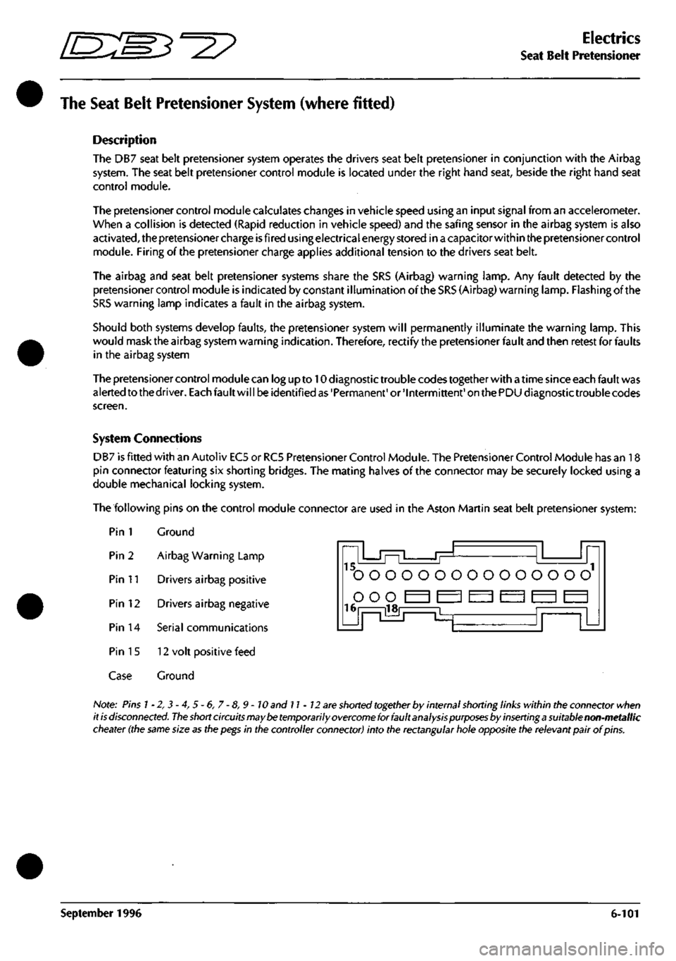
DB7 is fitted with an Autoliv ECS or RC5 Pretensioner Control Module. The Pretensioner Control Module has an 18
pin connector featuring six shorting bridges. The mating halves of the connector may be securely locked using a
double mechanical locking system.
The following pins on the control module connector are used in the Aston Martin seat belt pretensioner system:
Pin 1 Ground
' ' "L Pin 2 Airbag Warning Lamp
Pin 11 Drivers airbag positive
Pin 12 Drivers airbag negative
Pin 14 Serial communications
Pin 15 12 volt positive feed
Case Ground
15.
rrj ^
ooooooooooooooo
16 illn
^
Note: Pins
1
-2, 3 -4, 5 -6, 7 -8,9 -
10
and 11-12
are
shorted
together
by internal shorting links within the connector when
it
is
disconnected.
The
short circuits may
be
temporarily
overcome
for fault analysis
purposes
by inserting
a
suitable non-metallic
cheater
(the
sBfTiG
size
3s
the
p€gs
in the controller connector) into the rectsngul^r hole opposite the relevsnt p3ir of pins.
September 1996 6-101
Page 221 of 421

^^
Electrics
Seat Belt Pretensioner
Diagnostic Trouble Codes
050A Pretensioner squib leak to battery positive
050B Pretensioner squib leak to ground
050C Pretensioner squib high resistance
050D Pretensioner squib low resistance
0D13 Capacitor voltage error
0D14 Capacitor capacitance
0D09 Energy reserve sv^^itch
0D1
E
Energy shutdown switch
050E Seatbelt pretensioner switch error
0109 Accelerometer function
01OA Acceleration out of range
01 OB
Accelerometer offset
0209 Safing sensor error
030A Temperature sensor error
060C Warning lamp short circuit
060D Warning lamp open circuit
060E Warning lamp driver error
OAOC Analogue voltage error
0A09 Communications error
090A EEPROM not programmed
0909 EEPROM checksum
OAOA External watchdog error
OAOB External watchdog time out
020A Safing sensor not closed
090C RAM check error
Seat Beit Pretensioner Diagnostics
WARNING: To avoid the possibility of personal
injury caused by accidental deployment of the
pretensioner, disconnect the vehicle battery and
iva/f at least 10 minutes for all voltages to fully
discharge before working on the pretensioner
system. This covers the possibility of the normal
capacitor discharge circuits being inoperative and
failing to discharge the capacitor when instructed
to do
so.
WARNING: Do not make any electrical
measurements on the pretensioner
squib.
Electrical
measurement devices
can
induce sufficient voltage
to cause unintentional firing of the pretensioner
assembly
050 A Pretensioner Squib Leak to Battery
Positive
050A will be logged if the resistance of the
pretensioner squib feed or return line to a positive
potential falls below
1
k£2.
Procedure
1.
Read the warnings given at the start of this
pretensioner diagnostics section.
2.
Connect the PDU to the lower diagnostic socket
and access the pretensioner control module. Verify
that an 050A code is logged and note if the fault is
shown as intermittent. Note any other codes in the
DTC log and then clear all codes.
3. Switch off the ignition and wait at least 10 minutes
for the pretensioner squib firing capacitors to fully
discharge before continuing with this procedure.
4.
Disconnect the pretensioner squib connector at the
rearward harness. Disconnect the pretensioner
control module and temporarily cheat the squib
shorting link.
Note: The control module harness connector has a
shorting
link which short circuits
the
squib
lines together
when the connector is displaced. Carefully insert a
suitable non-metallic cheater to remove the short
circuit
between pins 11 and 12 before continuing with fault
diagnosis.
i"o
o o b 6 o ooooooooo'
I
ooo
Inserr cheater here
September 1996 6-105
Page 222 of 421

Electrics
Seat Belt Pretensioner 5^^?
Switch on the ignition and check for a positive
potential on the squib feed or return lines at the two
pins of the squib harness connector (activating
circuits in the rearward harness in turn may assist in
identifyingthe voltage
source).
Ifa positive potential
is detected, switch off and repair the circuit fault.
If no short circuit is detected in the rearward
harness, go to step 6.
With the ignition switched off and the pretensioner
squib disconnected, check the squib harness for
physical damage.
If any damage is detected, replace the complete
pretensioner squib assembly.
If no damage is detected, the fault is possibly in the
pretensioner control module. Replace the control
module.
Remove the cheater from the control module
connector.
'o o 0080 000000000' 000 ™ ^^ ^^^
ir Insert cheater here
Reconnect all components. Switch on the ignition
and test the vehicle to ensure that the problem is
resolved.
050B Pretensioner
Squib
Leakto Ground
050B will be logged if the resistance of the
pretensioner squib feed or return line to ground
falls below
Ikfi.
Procedure
1.
Read the warnings given at the start of this
pretensioner diagnostics section.
2.
Connect the PDU to the lower diagnostic socket
and access the pretensioner control module. Verify
that an 050B code is logged and note if the fault is
shown as intermittent. Note any other codes in the
DTC log and then clear all codes.
3. Switch offthe ignition and wait at least 10 minutes
for the pretensioner squib firing capacitors to fully
discharge before continuing with this procedure.
4.
Disconnect the pretensioner squib connector at the
rearward harness. Disconnect the pretensioner
control module and temporarily cheat the squib
shorting link.
Note: The control module harness connector has a
shorting link which
short
circuits
the squib lines together
when the connector is displaced. Carefully insert a
suitable non-metallic cheater to remove the
short circuit
between pins 11 and 12 before continuing with fault
diagnosis.
'o
o 00 8 o 000000000' 000
Insert cheater here
Check for a short circuit to vehicle ground on the
squib feed or return lines at the two pins of the squib
harness connector. If a short circuit is detected,
switch off and repair the circuit fault.
If no short circuit is detected in the rearward
harness, go to step 6.
With the ignition switched off and the pretensioner
squib disconnected, check the squib harness for
physical damage.
If any damage is detected, replace the complete
pretensioner squib assembly.
If no damage is detected, the fault is possibly in the
pretensioner control module. Replace the control
module.
Remove the cheater from the control module
connector. Reconnect all components. Switch on
the ignition and test the vehicle to ensure that the
problem is resolved.
6-106 September 1996
Page 223 of 421

D=27
Electrics
Seat Belt Pretensioner
050C Pretensioner Squib High Resistance 050D Pretensioner squib low resistance
050C will be logged if the resistance of the
pretensioner squib circuit rises above 4.5 ±0.5C2
050D will be logged if the resistance of the
pretensioner squib circuit falls below 1.4 ±0.4Q
Procedure
Read the warnings given at the start of this
pretensioner diagnostics section.
Connect the PDU to the lower diagnostic socket
and access the pretensioner control module. Verify
that an 050C code is logged and note if the fault is
shown as internnittent. Note any other codes in the
DTC log and then clear ail codes.
Switch off the ignition and wait at least 10 minutes
for the pretensioner squib firing capacitors to fully
discharge before continuing with this procedure.
Disconnect the pretensioner squib connector at the
rearward harness. Disconnect the pretensioner
control module and temporarily cheat the squib
shorting link.
3.
Procedure
Read the warnings given at the start of this
pretensioner diagnostics section.
Connect the PDU to the lower diagnostic socket
and accessthe pretensioner control module. Verify
that an 050D code is logged and note if the fault is
shown as intermittent. Note any other codes in the
DTC log and then clear all codes.
Switch off the ignition and wait at least 10 minutes
for the pretensioner squib firing capacitors to fully
discharge before continuing with this procedure.
Disconnect the pretensioner squib connector atthe
rearward harness. Disconnect the pretensioner
control module and temporarily cheat the squib
shorting link.
Note: The control module harness connector has a
shorting link which
short
circuits the squib
lines together
when the connector is displaced. Carefully insert a
suitable non-metallic
cheater to
remove
the short
circuit
between pins 11 and 12 before continuing with fault
diagnosis.
.j^ 'o o ob bo oooooooo
O O O
iV ^3 ^3 ^3 ^3 ^3 ^
lU Insert cheater here
Check the continuity of the squib feed and return
lines.
If any significant resistance is measured,
service the wiring as necessary.
Also check the condition of the connector pins for
damage or lack of tension and service
as
necessary.
If the circuit resistance is acceptable and the
connector pins are good, go to step 6.
If any defects are identified and serviced, go to step
7.
If the checks in step 4 are good, the high circuit
resistance must be in the pretensioner squib or in
thecontrol module. Replace the pretensioner squib
and reconnect all components.
Clearall logged DTCs from the pretensioner control
module and then test the vehicle.
If the 050C code is logged again, replace the
control module.
Note: The control module harness connector has a
shorting link which
short
circuits the squib
lines together
when the connector is displaced. Carefully insert a
suitable non-metallic
cheater to remove the
short circuit
between pins 11 and 12 before continuing with fault
diagnosis.
Insert cheater here
Check the continuity from the squib feed line to the
squib return line. With the shorting link cheated,
the resistance should be more than lOkQ. If the
resistance is less than 10kQ, service the wiring as
necessary.
Also check the connector pins for any damage
which could cause an unintentional short circuit.
If the checks in step 5 are good, the low circuit
resistance must be in the pretensioner squib or in
thecontrol module. Replace the pretensioner squib
and reconnect all components.
Clearall logged DTCs from the pretensioner control
module and then test the vehicle.
If the 050D code is logged again, replace the
control module.
September 1996 6-107
Page 224 of 421
Electrics
Seat Belt Pretensioner ^?
060C Warning Lamp Short Circuit
060C will be logged if the nnonitor current flow
through the SRS/Airbag warning lamp is excessive.
The warning lamp circuit is normally at 12 volts and
is switched to ground by the airbag control module
or by the pretensioner control module when one of
these control modules detects a fault.
If either control module connector is displaced and
the ignition is switched on, the warning lamp will
be illuminated via the ground shorting link between
pins!
and 2 ofthe pretensioner controller connector
or pins 4 and 5 of the airbag controller connector,
both control modules must be checked for the
appropriate DTC to isolate which circuit is at fault.
Procedure
1.
Connect the PDU to the lower diagnostic socket
and access the pretensioner control module. Verify
that an 060C code is logged and note if the fault is
shown as intermittent. Note any other codes in the
DTC log and then clear all codes. Go to step 2.
If fault code 060C is not logged, go to the diagnostics
section of the airbag system.
2.
Check the security of the pretensioner control
module connector.
If the connector is secure, go to step 3.
If the connector isdisplaced,resecu re theconnector.
Clear all logged DTCs and retest the vehicle to
ensure that the problem is resolved.
3. Access the SRS/Airbag warning lamp and check the
lamp resistance.
If the resistance is approximately
120£2,
the lamp is
good.
Refit the lamp and go to step 4.
If the resistance of the lamp is significantly less than
approximately 120^, fit a new lamp and refit the
instrument panel. Clear the logged DTCs from the
pretensioner control module and retest the vehicle
to ensure that the problem is resolved.
4.
If the checks in step 3 are good, the low circuit
resistance must be in the instrument pack or in the
control module. Replace the pretensioner control
module and reconnect all components.
6. Switch on the ignition and then test the vehicle.
If the 060C code is logged again, replace the
instrument pack.
060D Warning lamp open circuit
060D will be logged if the monitor current flow
through the SRS/Airbag warning lamp is below the
normal monitor level.
The warning lampcircuit is normally at 12 voltsand
is switched to ground by the airbag control module
or by the pretensioner control module when one of
these control modules detects a fault.
Procedure
Connect the PDU to the lower diagnostic socket
and access the pretensioner control module. Verify
that an 060D code is logged and note if the fault is
shown as intermittent. Note any other codes in the
DTC log and then clear all codes. Go to step 2.
lffaultcode060D is not
logged,
gotothediagnostics
section of the airbag system.
Switch off the ignition. Access the SRS/Airbag
warning lamp and check the lamp resistance. The
resistance should be approximately 120Q.
If the resistance is 120i2, go to step 3.
If the lamp resistance is significantly lower than
120^2,
replace the lamp. Retest the vehicle to
ensure that the problem is resolved.
Wait 10 minutes after switching off the ignition to
ensure that the pretensioner firing capacitors have
fully discharged.
Disconnect the pretensioner control module and
temporarily cheat the warning lamp shorting link.
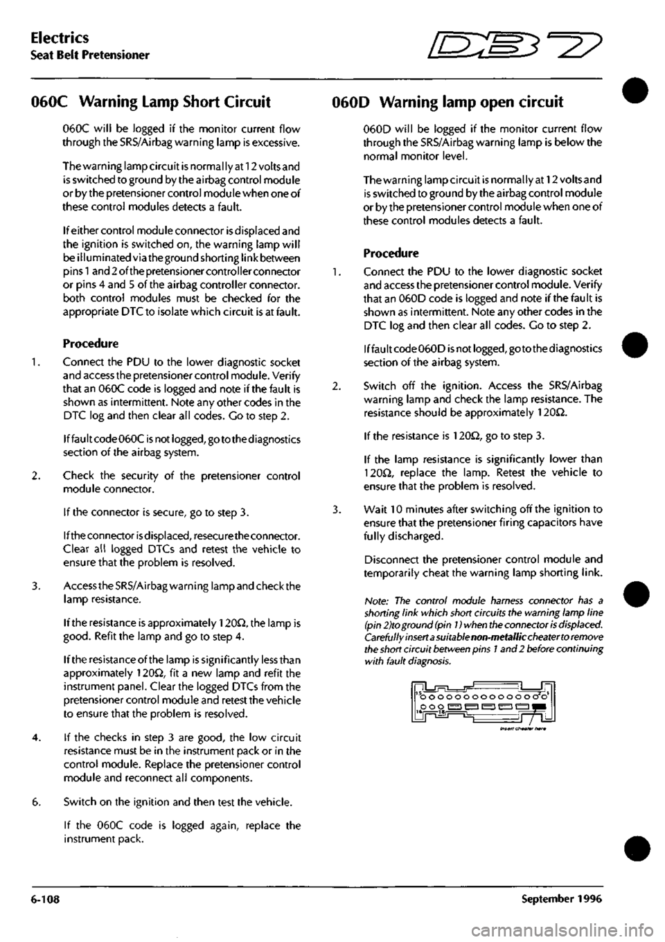
Note: The control module harness connector has a
shorting link which short circuits the warning lamp line
(pin 2)to ground
(pin
Dwhen
the
connector
is
displaced.
Carefully insert a suitable non-metallic cheater to remove
the
short
circuit
between
pins
1
and 2 before continuing
with fault
diagnosis.
ooooooooooooo o o poo
i^i
^ ^ ^ 1^1
Insert cheater hare
6-108
September
1996
Page 227 of 421
3-^?
Electrics
Seat Removal/Replacement 97.5 MY
6.6.03
Seat Removal 97.5 MY
Description
The 97.5 MY front seats are common to the DB7
Coupe
and
Volante
models.
Seat
switch
assembi ies
are located on the outboard side of both driver and
passenger
seats.
The front switch controls fore and
aft movement and the seat height adjustment. The
centre switch controls the recline adjustment. The
rear switch
controls
the
lumbar support adjustment.
The seat
heater switches are mounted on the centre
console, forward of the gear selector
lever.
Only one of
the
slide,
recline or height motors can
be driven under manual control at any one time.
Each seat switch pack is hard wired to the relevant
Seat Control
Module
beneath each
seat.
The
module
outputs are hard wired to the seat motors.
Removal
WARNING -
Seat
belt
Pretensioners
(if fitted):
To avoid the possibility
of
personal
injury
caused
by accidental deployment of the seat belt
pretensioner,
disconnect
the
vehicle battery and
wait at
least
10
minutes
for all
voltages
to fully
discharge
before working on the
pretensioner
system.
This covers the possibility
of
the normal
capacitor
discharge
circuits being inoperative and
failing to discharge the detonator capacitor when
instructed
to
do
so.
Procedure
1.
Motortheseatto
its
maximum forward position and
remove the fixings at the rear of the slides.
2.
Motor the seat to its maximum rearward position
and remove the front seat slide fixings.
3. Disconnect the battery
ground
(black)
lead.
Wait at
least 10 minutes for the pretensioner power supply
to fully discharge before working on the seat if a
pretensioner is fitted.
Note: Disconnect the battery within 12 seconds of
switching off the ignition to avoid the alarm siren sounding.
4.
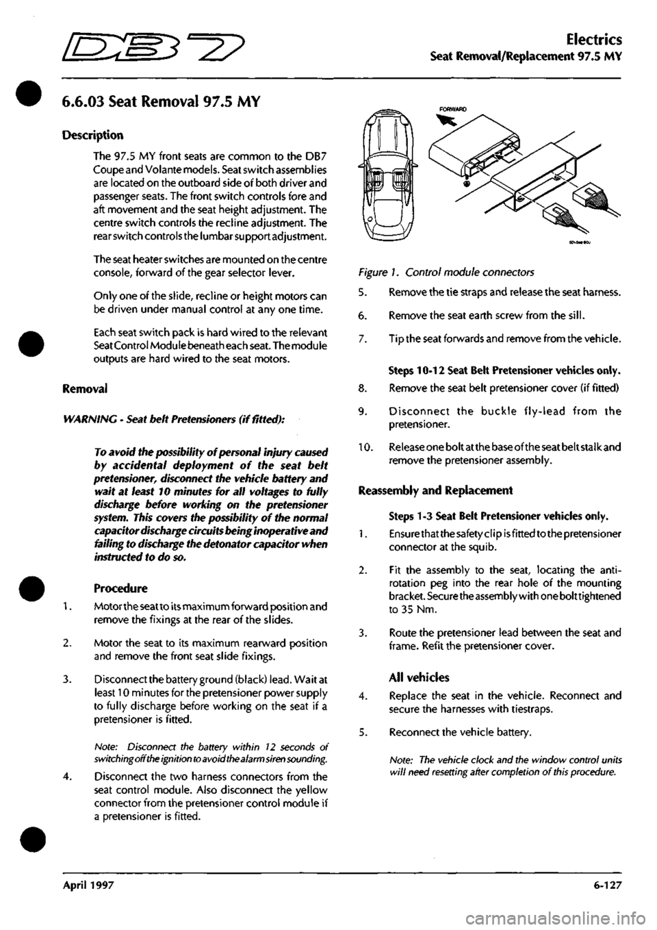
Disconnect the two harness connectors from the
seat control module. Also disconnect the yellow
connector from the pretensioner control module if
a pretensioner is fitted.
Figure 1. Control module connectors
5. Remove the tie straps and release the seat harness.
6. Remove the seat earth screw from the
sill.
7. Tip the seat forwards and remove from the vehicle.
Steps 10-12 Seat Belt Pretensioner vehicles only.
8. Remove the seat belt pretensioner cover (if fitted)
9. Disconnect the buckle fly-lead from the
pretensioner.
10.
Release
one
bolt at
the
base of the
seat
belt stalk and
remove the pretensioner assembly.
Reassembly and Replacement
Steps 1-3 Seat Belt Pretensioner vehicles only.
1.
Ensurethatthesafetyclipisfittedtothepretensioner
connector at the squib.
2.
Fit the assembly to the seat, locating the
anti-
rotation peg into the rear hole of the mounting
bracket.
Securethe
assembly with
one
bolttightened
to 35 Nm.
3. Route the pretensioner lead between the seat and
frame.
Refit the pretensioner
cover.
All vehicles
4.
Replace the seat in the vehicle. Reconnect and
secure the harnesses with tiestraps.
5. Reconnect the vehicle battery.
Note:
The vehicle clock and the window control units
will
need resetting after completion
of
this
procedure.
April 1997 6-127
Page 229 of 421
O" D^?
Body and Trim
Contents
Contents
Body and Trim
Body Repair
Potential Risks
Precautions
General Repair Notes
Steel Body Parts - Repair, Remove and Replace
RTM Body Parts
Body Panel and Trim Removal
Front Apron
Front Undertray
Wheel Arch Liners
Side Sills (top fixings)
Side Sills (bottom fixings)
Rear Bumper
Doors
Door Liners
Door Liner (components)
Steering Wheel
Column Switches
Instrument Panel (surround)
Instrument Panel
Facia Underscuttles
Glove Box
Facia Mountings (1)
Facia Mountings (2)
Console Instruments
Radio
Front Seats
Ashtray
Centre Console
Seat ECU Covers
Rear Console
Rear Seats and C Post Trim
Quarter Panels, B Post Panels, Parcel Shelf
Headlining
Roof System Description and Repair Procedures
Vol ante Roof
Roof and Rear Quarter Light Control
Roof Component Location
Roof Control System
9.0.02.1
Roof Removal/Replacement
9.0.02.3
Roof Hydrailic Control System
9.0.02.5
Bleeding the Roof Hydraulic System
9.1.01.1
Rear Quarter Window Renewal
9.1.01.2
Rear Quarter Glass Adjustment
9.1.01.4
Rear Quarter Window Lift Motor - LH
9.1.01.5
Rear Quarter Window Lift Motor - RH
Roof Sealing and Wind Noise
9.2.01.5
'A' Post/Header Sealing and Lock Adj
9.2.01.6
Roof Seals - Adjustment
9.2.01.7
Cheater Plate Seals - Adjust/Renew
9.2.01.8
Door Glass Adjustment
Alcantara Cleaning
7-1
7-2
7-2
7-3
7-3
7-4
7-5
7-6
Sheet 1
Sheet 2
Sheet 3
Sheet 4
Sheet 5
Sheet 6
Sheet 7
Sheet 8
Sheet 9
Sheet 10
Sheet 11
Sheet 12
Sheet 13
Sheet 14
Sheet 15
Sheet 16
Sheet 17
Sheet 18
Sheet 19
Sheet 20
Sheet 21
Sheet 22
Sheet 23
Sheet 24
Sheet 25
Sheet 26
Sheet 27
7-7
7-7
7-8
7-9
7-10
7-11
7-12
7-13
7-14
7-15
7-16
7-17
7-17
7-18
7-19
7-20
7-21
May 1996 7-1
Page 272 of 421
^^2?
Body and Trim
Roof Sealing and Wind Noise
Roof Sealing and Wind Noise
Roof seals and side windows have been provided
with
a range
ofadjustments capable ofdealing with
any leaks which may occur.
The following information is divided into five
sections:
1.
A post and header sealing/roof lock adjustment
2.
Roof seals - adjustment
3. Cheater plate seals - adjustment/renewal
4.
Door glass - adjustment
5. Rear quarter glass - adjustment (9.1.01.2)
When a leak is
reported,
either wind noise or water
ingress, try to pinpoint the actual leak path using
any of the following methods:
• An ultrasonic leak detector
• An air flow
detector,
e.g.
Drager
smoke
tube
• Paper test strips at seal contact areas
9.2.01.5 - 'A' Post/Header Sealing and
Lock Adjustment
when a leak is detected at the top of the 'A' post
adjacent to the header rail
seal,
first
ensure
that the
roof lock is correctly adjusted.
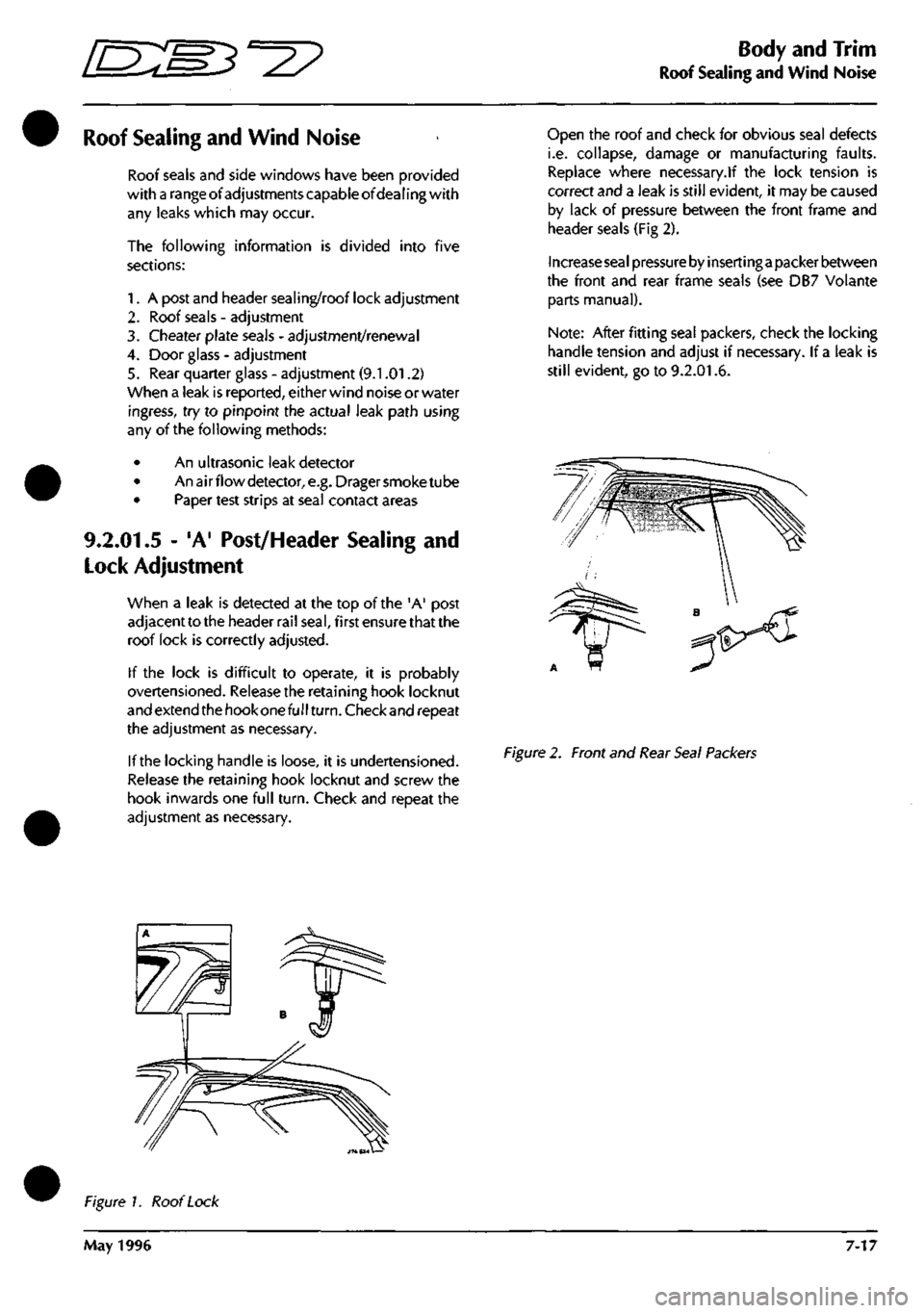
If the lock is difficult to operate, it is probably
overtensioned. Release the retaining hook locknut
and extend
the hook
one full
turn.
Checkand repeat
the adjustment as necessary.
If the locking handle is loose, it is undertensioned.
Release the retaining hook locknut and screw the
hook inwards one full
turn.
Check and repeat the
adjustment as necessary.
Open the roof and check for obvious seal defects
i.e. collapse, damage or manufacturing faults.
Replace where necessary.lf the lock tension is
correct and a leak is still evident, it may be caused
by lack of pressure between the front frame and
header seals (Fig 2).
Increase seal pressure by inserting a
packer between
the front and rear frame seals (see DB7 Volante
parts manual).
Note:
After fitting
sea!
packers, check the locking
handle tension and adjust if necessary. If
a
leak is
still evident, go to 9.2.01.6.
Figure
2. Front and
Rear Seal Packers
Figure 1. Roof
Lock
May 1996 7-17