ad blue ASTON MARTIN DB7 1997 Owner's Guide
[x] Cancel search | Manufacturer: ASTON MARTIN, Model Year: 1997, Model line: DB7, Model: ASTON MARTIN DB7 1997Pages: 421, PDF Size: 9.31 MB
Page 315 of 421
Air Conditioning
Manifold Gauge Set 5=2?
Manifold Gauge Set
The manifold gauge set is a most important tool for
fault diagnosis and system efficiency assessment.
The relationship to each other of HIGH and LOW
pressures and their correlation to AMBIENT and
EVAPORATOR temperatures must be compared to
determine system status. Because oi the heavy
reliance upon this piece of equipment for service
diagnosis, ensure that the gauges are calibrated
regularly and the equipment is treated with care.
BLUE LOW SIDE RED HIGH SIDE
LOW
m
m
Manifold.
The manifold is designed to control refrigerant
flow. When connected into the system, pressure is
registered on both gauges at all times. During
system tests both the high and low side hand valves
should be closed (rotate clockwise to seat the
valves). The hand valves isolate the low and the
high sides from the centre (service) hose.
Low Side Pressure Gauge.
This compound gauge
is
designed to register positive
and negative pressure and may be calibrated as
follows:
• Full Scale Deflection - 0 to 24 bar pressure
in a clockwise direction
• Otol bar FSD negative pressure in a counter
clockwise direction.
High Side Pressure Gauge.
This pressure gauge may be calibrated from 0 to 34
bar FSD inaclockwisedirection. Depending on the
manufacturer, this gauge may also be of the
compound type.
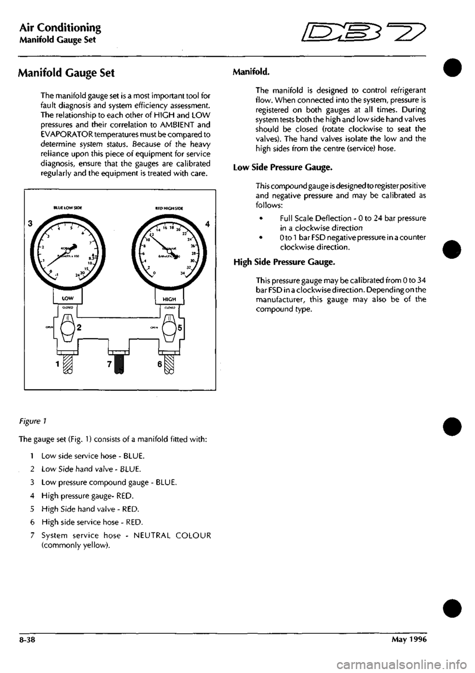
Figure 1
The gauge set (Fig. 1) consists of a manifold fitted
with:
1 Low side service hose - BLUE.
2 Low Side hand valve - BLUE.
3 Low pressure compound gauge - BLUE.
4 High pressure gauge- RED.
5 High Side hand valve - RED.
6 High side service hose - RED.
7 System service hose - NEUTRAL COLOUR
(commonly yellow).
8-38 May 1996
Page 318 of 421
=2?
Air Conditioning
System Checking with the Manifold Gauge Set
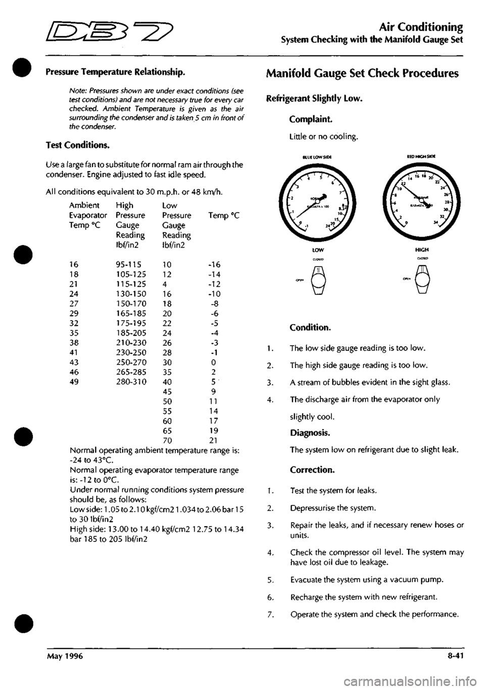
Pressure Temperature Relationship.
Note:
Pressures
shown are under exact conditions
(see
test
conditions) and
are
not
necessary
true for every
car
checked.
Ambient Temperature is given as the air
surrounding the
condenser
and
is
taken 5 cm in front of
the
condenser.
Test Conditions.
Use a large fan to substitute for normal ram air through the
condenser. Engine adjusted to fast idle speed.
All conditions equivalent to 30 m.p.h. or 48 km/h.
Ambient
Evaporator
Temp °C
16
18
21
24
27
29
32
35
38
41
43
46
49
High
Pressure
Gauge
Reading
Ibf/in2
95-115
105-125
115-125
130-150
1
50-170
165-185
175-195
185-205
210-230
230-250
250-270
265-285
280-310
Low
Pressure
Gauge
Reading
Ibf/in2
10
12
4
16
18
20
22
24
26
28
30
35
40
45
50
55
60
65
70
Ten
-16
-14
-12
-10
-8
-6
-5
-4
-3
-1
0
2
5
9
11
14
17
19
21
Normal operating ambient temperature range is:
-24 to 43°C.
Normal operating evaporator temperature range
is:-12toO°C.
Under normal running conditions system pressure
should be, as follows:
Lowside:1.05to2.10kgf/cm21.034to2.06bar15
to 30 ibf/in2
High side: 13.00 to 14.40 kgf/cm2 12.75 to 14.34
bar185to205lbf/in2
Manifold Gauge Set Check Procedures
Refrigerant Slightly Low.
Complaint.
Little or no cooling.
1.
2.
3.
4.
1.
2.
3.
4.
5.
6.
7.
BLUE LOW SIDE
KED
HIGH SIDE
Condition.
The low side gauge reading is too low.
The high side gauge reading is too low.
A stream of bubbles evident in the sight glass.
The discharge air from the evaporator only
slightly
cool.
Diagnosis.
The system low on refrigerant due to slight leak.
Correction.
Test the system for leaks.
Depressurise the system.
Repair the leaks, and if necessary renew hoses or
units.
Check the compressor oil level. The system may
have lost oil due to leakage.
Evacuate the system using a vacuum pump.
Recharge the system with new refrigerant.
Operate the system and check the performance.
May 1996 8-41
Page 320 of 421
^2?
Air Conditioning
System Checking with the Manifold Gauge Set
Compressor Malfunction
Complaint.
Cooling is not adequate.
Condenser Malfunction or System Overcharge
Complaint.
Little or no cooling. Overheating of the engine may
also be noted.
BLUE LOW SIDE
BLUE
LOW SIDE BED HICH SIDE
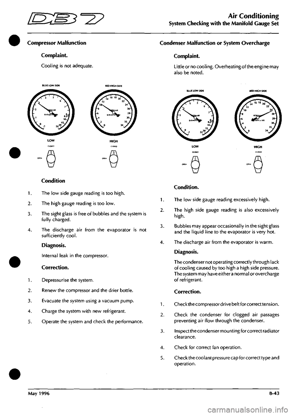
Condition
1.
The low side gauge reading is too
high.
2.
The high gauge reading is too low.
3. The sight glass is free of bubbles and the system is
fully charged.
4.
The discharge air from the evaporator is not
sufficiently
cool.
Diagnosis.
Internal leak in the compressor.
Correction.
1.
Depressurise the system.
2.
Renew the compressor and the drier bottle.
3. Evacuate the system using a vacuum pump.
4.
Charge the system with new refrigerant.
5. Operate the system and check the performance.
HIGH
Condition.
1.
The low side gauge reading excessively
high.
2.
The high side gauge reading is also excessively
high.
3. Bubbles may appear occasionally in the sight glass
and the liquid line to the evaporator is very hot.
4.
The discharge air from the evaporator is warm.
Diagnosis.
The condenser not operating correctly through lack
of cooling caused by too high a high side pressure.
The system may have either
a
normal or overcharge
of refrigerant.
Correction.
1.
Checkthecompressordrivebeltforcorrecttension.
2.
Check the condenser for clogged air passages
preventing air flow through the condenser.
3. Inspect the condenser mounting for correct radiator
clearance.
4.
Check for correct fan operation.
5. Check the coolant pressure capfor correct type and
operation.
May 1996 8-43
Page 321 of 421
Air Conditioning
System Checking with the Manifold Gauge Set ffi:S5=27
After making the above checks operate the system
and check the performance. If the Condition is not
rectified.
1.
inspect the system for overcharge of refrigerant and
rectify as follows.
A. Discharge the system, until a stream of bubbles
appear in the sight glass and both gauge readings
drop to below normal.
B. Add new refrigerant until the bubbles disappear
and the pressures are normal. Then add 0.25 to 0.5
lb.
of additional refrigerant.
2.
Operate the system and check the performance.
If the gauge readings are still too
high.
3. Depressurise the system.
3. Removeand inspectthecondenserforoilclogging.
Clean and flush the condenser to ensure the free
passage refrigerant or renew the condenser.
4.
Renew the receiver-drier.
5. Evacuatethesystem using
a
vacuum pump Recharge
the system with new refrigerant. Operate the system
and check the performance
Moisture in the System
Complaint.
Cooling notadequateduringthe hot part of theday.
Note: Cooling may
be satisfactory
during
early
morning/
late evening
but
inadequate
during
the
hot part of
the
day.
BLUE LOW SIDE RED HIGH SIDE
1.
2.
3.
4.
5.
LOW
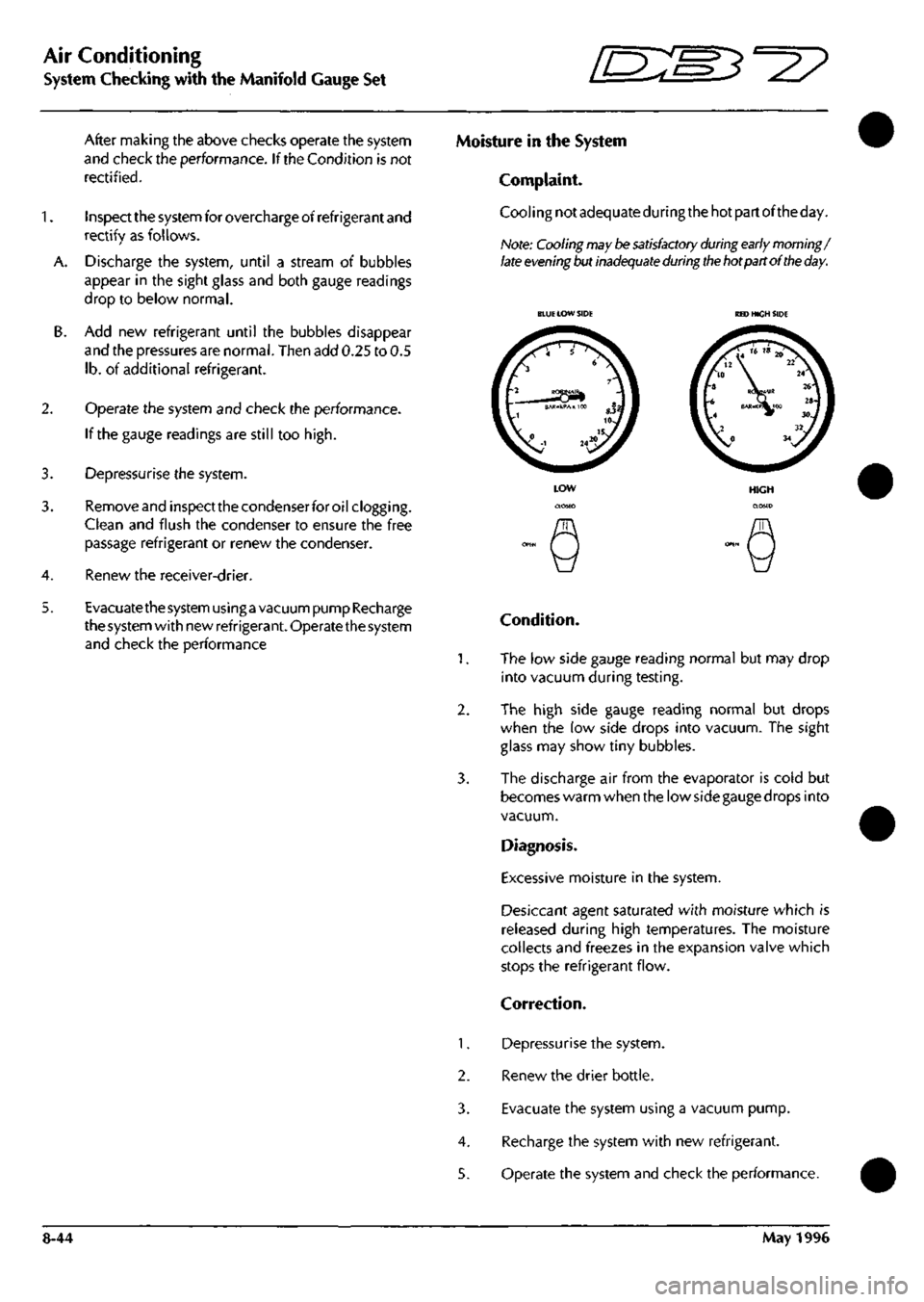
Condition.
The low side gauge reading normal but may drop
into vacuum during testing.
The high side gauge reading normal but drops
when the low side drops into vacuum. The sight
glass may show tiny bubbles.
The discharge air from the evaporator is cold but
becomes warm when the low side gauge drops into
vacuum.
Diagnosis.
Excessive moisture in the system.
Desiccant agent saturated with moisture which is
released during high temperatures. The moisture
collects and freezes in the expansion valve which
stops the refrigerant flow.
Correction.
Depressurise the system.
Renew the drier bottle.
Evacuate the system using a vacuum pump.
Recharge the system with new refrigerant.
Operate the system and check the performance.
8-44 May 1996
Page 322 of 421
=2?
Air Conditioning
System Checking with the Manifold Gauge Set
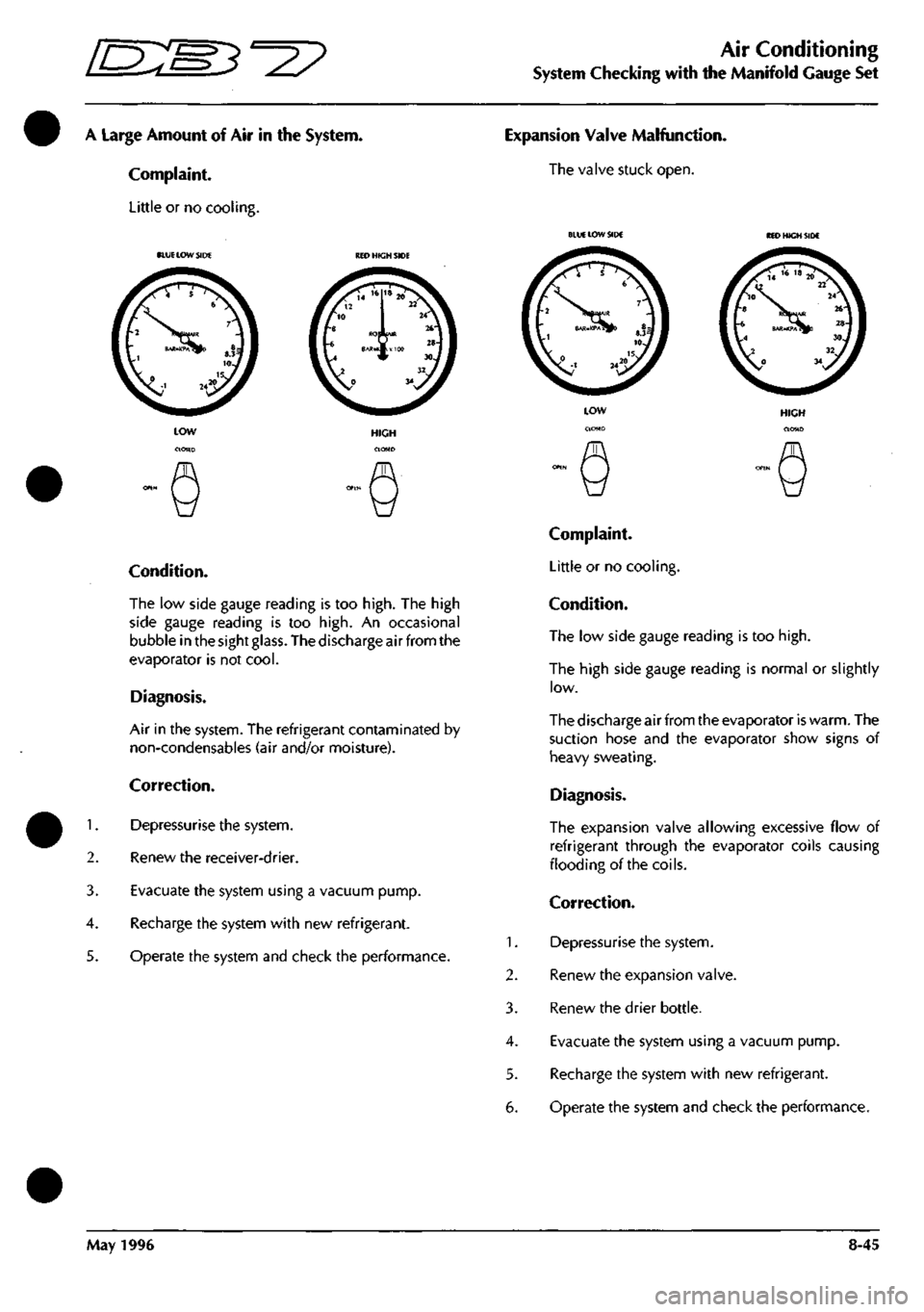
A Large Amount of Air in the System.
Complaint.
Little or no cooling.
1.
2.
3.
4.
5.
BLUE
LOW SIDE RED HIGH SIDE
Condition.
The low side gauge reading is too
high.
The high
side gauge reading is too
high.
An occasional
bubble in the sight
glass.
The discharge air from the
evaporator is not
cool.
Diagnosis.
Air in the system. The refrigerant contaminated by
non-condensables (air and/or moisture).
Correction.
Depressurise the system.
Renew the receiver-drier.
Evacuate the system using a vacuum pump.
Recharge the system with new refrigerant.
Operate the system and check the performance.
Expansion Valve Malfunction.
The valve stuck open.
1.
2.
3.
4.
5.
6.
BLUE LOW SIDE
HIGH
Complaint.
Little or no cooling.
Condition.
The low side gauge reading is too
high.
The high side gauge reading is normal or slightly
low.
The discharge air from the evaporator is warm. The
suction hose and the evaporator show signs of
heavy sweating.
Diagnosis.
The expansion valve allowing excessive flow of
refrigerant through the evaporator coils causing
flooding of the coils.
Correction.
Depressurise the system.
Renew the expansion valve.
Renew the drier bottle.
Evacuate the system using a vacuum pump.
Recharge the system with new refrigerant.
Operate the system and check the performance.
May 1996 8-45
Page 323 of 421
Air Conditioning
System Checking with the Manifold Gauge Set ^^?
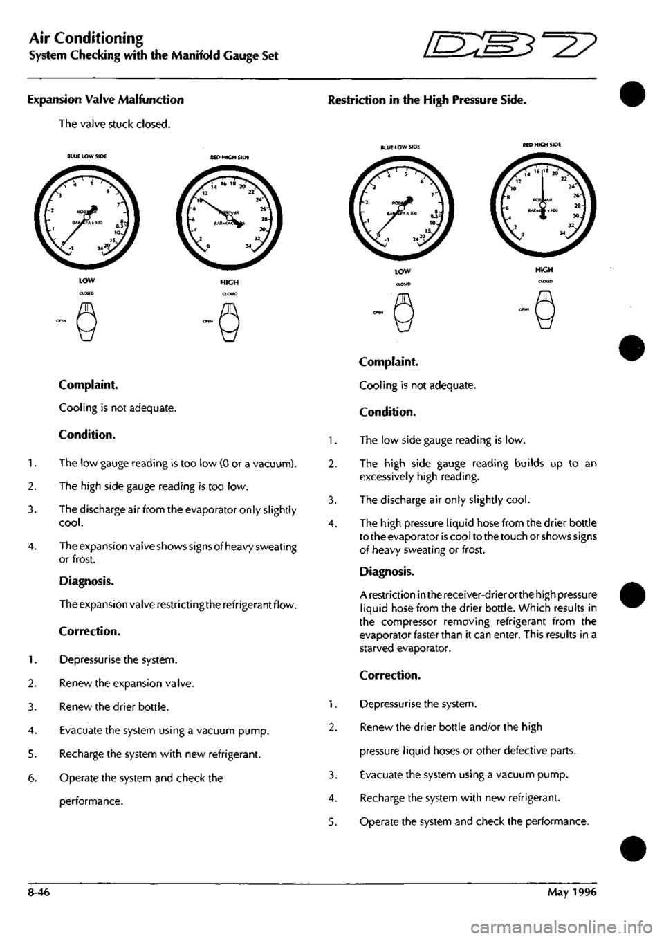
Expansion Valve Malfunction
The valve stuck closed.
Restriction in the High Pressure Side.
BLUE LOW SIDE SED HIGH SIDE
Complaint.
Cooling is not adequate.
Condition.
1.
The low gauge reading is too low (0 or a vacuunn).
2.
The high side gauge reading is too low.
3. The discharge air from the evaporator only slightly
cool.
4.
The expansion valve shows signs of heavy sweating
or frost.
Diagnosis.
The expansion valve restrictingthe refrigerant flow.
Correction.
1.
Depressurise the system.
2.
Renew the expansion valve.
3. Renew the drier bottle.
4.
Evacuate the system using a vacuum pump.
5. Recharge the system with new refrigerant.
6. Operate the system and check the
performance.
1.
2.
3.
4.
1.
2.
3.
4.
5.
BLUE LOW SIDE
Complaint.
Cooling is not adequate.
Condition.
The low side gauge reading is low.
The high side gauge reading builds up to an
excessively high reading.
The discharge air only slightly
cool.
The high pressure liquid hose from the drier bottle
to the evaporator is cool to the touch or shows signs
oi heavy sweating or frost.
Diagnosis.
A restriction in the receiver-drier orthe high pressure
liquid hose from the drier bottle. Which results in
the compressor removing refrigerant from the
evaporator faster than it can enter. This results in a
starved evaporator.
Correction.
Depressurise the system.
Renew the drier bottle and/or the high
pressure liquid hoses or other defective parts.
Evacuate the system using a vacuum pump.
Recharge the system with new refrigerant.
Operate the system and check the performance.
8-46 May 1996
Page 324 of 421
^?
Air Conditioning
Torque Settings / Depressurising the System
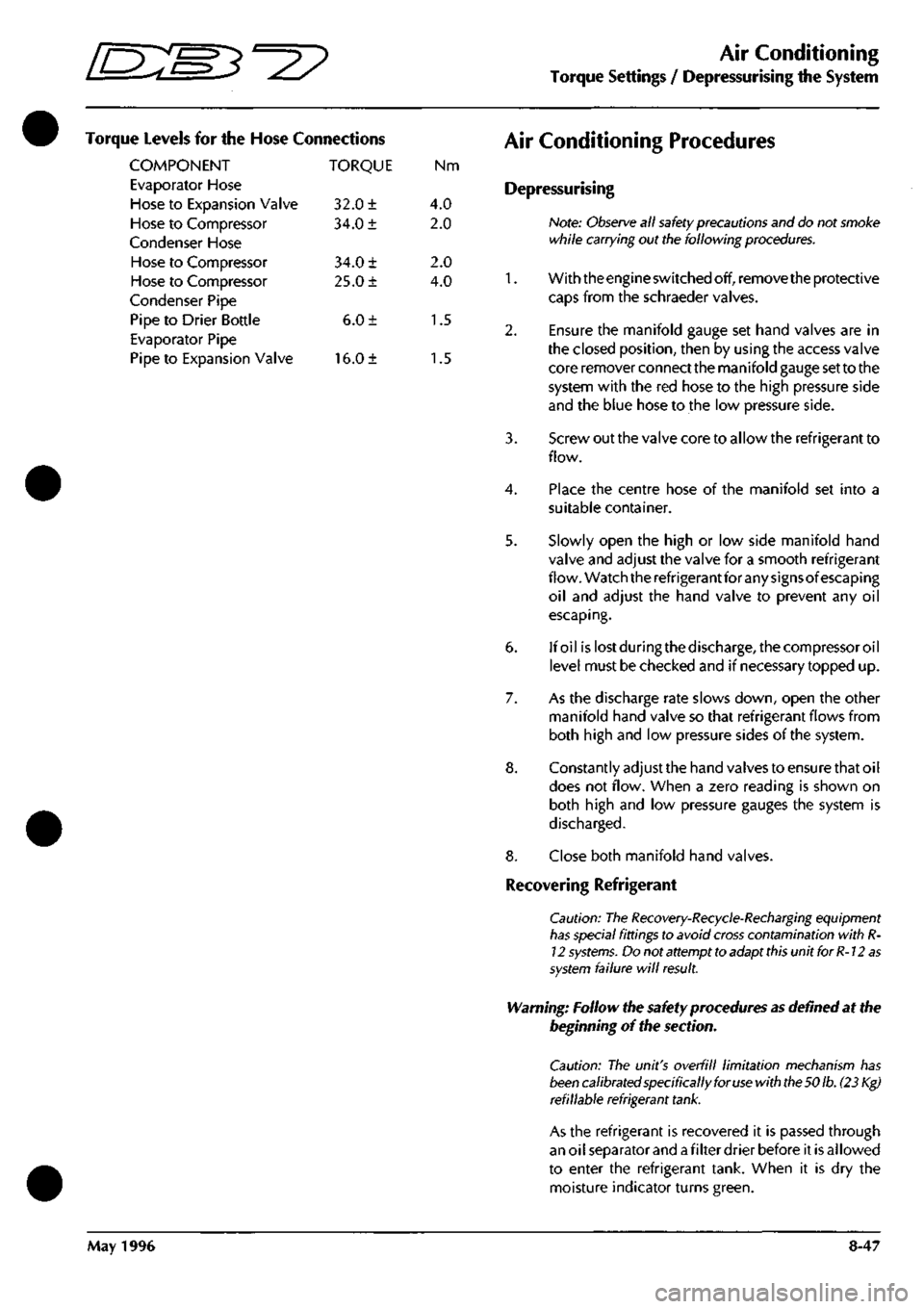
Torque Levels for the Hose Connections
COMPONENT TORQUE Nm
Evaporator Hose
Hose to Expansion Valve 32.0 ± 4.0
Hose to Compressor 34.0 ± 2.0
Condenser Hose
Hose to Compressor 34.0 ± 2.0
Hose to Compressor 25.0 ± 4.0
Condenser Pipe
Pipe to Drier Bottle 6.0 ± 1.5
Evaporator Pipe
Pipe to Expansion Valve 16.0 ± 1.5
Air Conditioning Procedures
Depressurising
Note:
Observe
all
safety
precautions and do not smoke
while carrying out the following
procedures.
1.
With the engine switched off, remove the protective
caps from the schraeder valves.
2.
Ensure the manifold gauge set hand valves are in
the closed position, then by using the access valve
core remover connect the manifold gauge set to the
system with the red hose to the high pressure side
and the blue hose to the low pressure side.
3. Screw out the valve core to allow the refrigerant to
flow.
4.
Place the centre hose of the manifold set into a
suitable container.
5. Slowly open the high or low side manifold hand
valve and adjust the valve for a smooth refrigerant
flow. Watch the refrigerant for any signsof escaping
oil and adjust the hand valve to prevent any oil
escaping.
6. If oil islostduringthedischarge,thecompressoroil
level must be checked and if necessary topped up.
7. As the discharge rate slows down, open the other
manifold hand valve so that refrigerant flows from
both high and low pressure sides of the system.
8. Constantly adjust the hand valves to ensure that oil
does not flow. When a zero reading is shown on
both high and low pressure gauges the system is
discharged.
8. Close both manifold hand valves.
Recovering Refrigerant
Caution: The
Recovery-Recycle-Recharging
equipment
has
special fittings to avoid
cross
contamination with
R-
12
systems.
Do not attempt to adapt
this
unit for
R-12
as
system
failure will
result.
Warning: Follow the safety procedures
as
defined at the
beginning of the section.
Caution: The unit's overfill limitation mechanism has
been
calibrated specifically for
use
with
the 50
lb.
(23 Kg)
refillable refrigerant
tank.
As the refrigerant is recovered it is passed through
an oil separator and
a
filter drier before it is allowed
to enter the refrigerant tank. When it is dry the
moisture indicator turns green.
May 1996 8-47
Page 325 of 421
Air Conditioning
Refrigerant Recovery and Recycling ^=2?
Recovery Procedure
Hote:
Run the
air-conditioning
system
for
a
few
minutes
before starting the
recovery
procedure as
this will
enable
more refrigerant to be recovered. Turn the
system
off
before
starting
the procedure.
1.
Attach the red (high side) hose oftheunittothe high
side fitting of the system on the vehicle then fit the
blue (low side) fitting to the low side on the vehicle.
Note: Make sure that the Air conditioning
system
has
pressure in it before beginning the recovery
process;
if
there is no
system
pressure there is no refrigerant to
recover.
Also
make sure that the
oil
drain
valve
is
closed.
2. Open both the high and low side valves on the
control panel.
3. Open the red CAS (vapour) valve and the blue
LIQUID valve on the tank.
4.
Turn on the MAIN POWER switch.
5. Press the RECOVERY key on the key-pad. The
display shows that the unit in the RECOVER mode
and AUTOMATIC cycle. After the compressor starts
the display shows the weight of refrigerant being
recovered.
The compressor shuts off automatically
when the recovery is complete and the display
shows the message 'CPL' and the final weight of the
recovered refrigerant.
6. Wait for five minutes and watch the manifold
gauges for a rise above 0. If a rise occurs press the
HOLD/CONT key. Repeat as needed until the
system pressure holds for two minutes.
Note: Drain the oil
separator
after
each
job.
7. Slowly open the oil drain valve and drain the oil
into the oil catch bottle. When all the recovered oil
has completely drained close the valve.
8. Replace oil lost during the recovery procedure by
measuringthe amount of oil inthe catch bottle and
adding the same amount of new oil to the system.
Note:
Dispose
of the
recovered
oil in an approved way.
9. When the recovery tank is full the compressor is
shut off and the display shows the message FULL.
Evacuating and Recycling the Refrigerant
1.
Open the red (high side) and the blue (low side)
valves on the unit and open the red GAS (vapour)
valve and the blue LIQUID valve on the tank.
2.
Enter the required time using the key-pad, press
enter,thedisplayshowstheenteredtime in minutes.
3. Start the vacuum pump by pressing the VACUUM
KEY again. The recycling process begins
approximately five seconds after the vacuum pump
starts and the message RECYCLE is displayed.
Note: If the vacuum pump
has
run for ten hours or
over
without an oil change the
message
OIL
flashes
on the
display.
Change
the pump oil and
then press
the
SHIFT/
RESET key and
the
zero key to
reset the
oil
change
timer
to zero.
The digital display counts down the evacuation
time.
4.
Check for non-condensibles after five minutes
recycling.
Ifthegauge needles are more than lOpsi
apart purge the non-condensibles from the tank by
open
i ng
the purge valve on the back of the
un
it and
continue to bleed until both needles show the same
reading.
The vacuum sequence continues until the
programmed time has elapsed at which point the
message CPL is displayed.
5. If the moisture indicator turns green recharge with
refrigerant.
or
5. If the moisture indicator has not turned green
replace the unit's filter-drier, which is probably
saturated.
Note:
Pressing
any key at this point allows the next
function to be
accessed.
To recycle the refrigerant only without pulling a
vacuum for an indefinite period of time press the
SHIFT/RESET key and the RECYCLE key on the key
pad.
Press the SHIFT/RESET key to cancel.
For vacuum only press the SHIFT/RESET key and
the ENTER key and then press
"1".
Run the vacuum
pump as long as required and then press
"1"
or
press SHIFT/RESET to cancel.
8-48 May 1996
Page 374 of 421
^?
The Aston Martin Lagonda Diagnostic System
Installation Instructions
1.
Switch off the PDU and remove all cables.
2.
Remove the cover screw (Fig 23) and remove the cover.
3. If damaged, remove the old foam gasket from the cover and replace with the new one supplied.
4.
Note the orientation of the connector. Disconnect the connector and remove the old battery pack.
5. Fit and connect the new battery pack (Fig 24) with the black cable towards the touch screen.
6. Refit the cover and cover screw.
7. Refer to the Battery Charging instructions for recharging times.
Changing the Dust Filter
The electronic module has a dust filter fitted to the underside of the module. Every three months a new filter wil
be supplied. To change the filter, proceed as follows:
1.
Switch off the mains supply and pull out the old filter (Fig 25).
2.
Feed in the new filter with the blue side facing in, pushing it well into the corners of the holder.
3. Switch on the mains supply.
Figure 25. Dust filter replacement Figure 26. Support arm adjustment
Support Arm Adjustment
Periodically the support arm mechanism may require adjustment.
1.
Remove the cross head arm fixing screw.
2.
Using a suitable screwdriver, turn the tensioning screw (Fig 26) anti-clockwise half a
turn.
3. Refit the leg fixing screw and repeat the operation on the opposite side.
4.
Check that the arm tension is enough to support the weight of the PDU without movement.
VIA Carrying Case
The VIA unit (0018) is secured into its carrying case with two fixing screws from the underside of the case. If a new
VIA is required, remove the two fixing screws and lift the VIA from the carrying case. Return only the VIA for
replacement, do not return the carrying case.
May 1996 9-23
Page 400 of 421
^^
The Aston Martin Lagonda Diagnostic System
Users Guide
Print Facility
The print trace and print screen facilities provided on
DB7 CD2 will enable the Dealer to print directly to a
serial printer via an isolated RS 232 cable.
General Information
This cable isdesigned to provide full electrical isolation
between the Portable Diagnostic Unit (PDU) and a
device using the RS232 serial communication port.
The cable is constructed with an in-line module that
contains the optical isolation circuitry, powered from
the PDU.
Printer type
The cable is supplied configured to suite an Epson
LX300 printer. This is the only instal lation verified and
approved by Aston Martin Lagonda Ltd.
Unexpected results may occur if used with an
unapproved printer.
Part Number Equipment type
3539-1114-03 Epson LX300 printer cable kit
comprising
3539-1169-03 Printer Cable
3539-1175-02 User Self Test Adaptor
Connecting to the PDU
Connection to the PDU RS232 port
is
made by plugging
the circular connector with the BLUE ident ring into
socket (1) on the PDU interface panel.
RS232 Protocol
The RS232 protocol operated by the PDU is 9600
baud,
8 bit, no parity,
1
stop bit,
RTS
/ CTS hardware
handshake.
Printer Configuration
When connected to the printer
a
hardcopy of the PDU
data can be produced.
25 Way Connector c rp '*= Isolator •—*«
RS232 Cable
Printer Connection
Printer
When connecting to the printer please record original
printer settings prior to making any changes. Neither
CenRad nor Aston Martin Lagonda can accept
responsibility for re-configuration of the printer for
other applications.
Self Test Adaptor
Each cable type is supplied with a User Self Test (UST)
adaptor. This allows the function of the cable to be
verified independently of a printer. Future releases of
UST software will include testing procedures for this
cable.
RS232 Printer Cable
September 1996 9-49