trunk ASTON MARTIN DB7 1997 Workshop Manual
[x] Cancel search | Manufacturer: ASTON MARTIN, Model Year: 1997, Model line: DB7, Model: ASTON MARTIN DB7 1997Pages: 421, PDF Size: 9.31 MB
Page 14 of 421
Electrics
Starter Motor / Steering Wheel - Removal Procedures ^n:M3^^2?
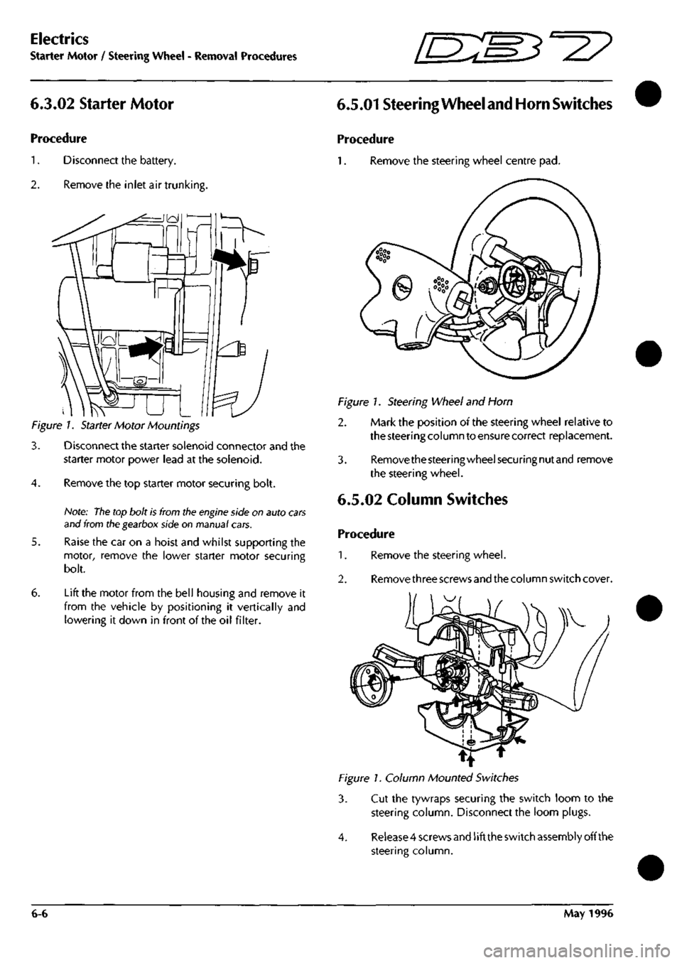
6.3.02 Starter Motor
Procedure
1.
Disconnect the battery.
2.
Remove the inlet air trunkins
Figure 1. Starter Motor Mountings
3. Disconnect the starter solenoid connector and the
starter motor power lead at the solenoid.
4.
Remove the top starter motor securing bolt.
Note:
The
top bolt is from tlie
engine
side on auto
cars
and from ttie gearbox side on manual cars.
5. Raise the car on a hoist and whilst supporting the
motor, remove the lower starter motor securing
bolt.
6. Lift the motor from the bell housing and remove it
from the vehicle by positioning it vertically and
lowering it down in front of the oil filter.
6.5.01 Steering
Wheel and Horn
Switches
Procedure
1.
Remove the steering wheel centre pad.
Figure 1. Steering Wheel and Horn
2. Mark the position of the steering wheel relative to
the steering column to ensure correct replacement.
3. Removethesteeringwheelsecuringnutand remove
the steering wheel.
6.5.02 Column Switches
Procedure
1.
Remove the steering wheel.
2.
Remove three screws and the column switch cover.
1^
Figure 1. Column Mounted Switches
3. Cut the tywraps securing the switch loom to the
steering column. Disconnect the loom plugs.
4.
Release 4 screws and
1
ift the switch assembly off the
steering column.
6-6 May 1996
Page 130 of 421
![ASTON MARTIN DB7 1997 Workshop Manual
^^?
Electrics
Relay Location Chart - 97 MY
11
Left Forward
Chassis
Facia Component Chassis.
Passengers Side RHD
FrVjQJElElE]
\V<^
EIEIEIBE]
7ir6 ^
Facia Component Chassis
Drivers Side LH ASTON MARTIN DB7 1997 Workshop Manual
^^?
Electrics
Relay Location Chart - 97 MY
11
Left Forward
Chassis
Facia Component Chassis.
Passengers Side RHD
FrVjQJElElE]
\V<^
EIEIEIBE]
7ir6 ^
Facia Component Chassis
Drivers Side LH](/img/52/56976/w960_56976-129.png)
^^?
Electrics
Relay Location Chart - 97 MY
11
Left Forward
Chassis
Facia Component Chassis.
Passengers Side RHD
FrVjQJElElE]
\V<^
EIEIEIBE]
7ir6 ^
Facia Component Chassis
Drivers Side LHD
Boot (Trunk)
Chassis
Coupe •
E]
m
m
in
6
•
8
Right Forward
Chassis
1
T
T
T
Facia Component Chassis
Drivers Side RHD
nmr^if^
9
||T|
|6||7 1
|T|
•w'^npti
Facia Component Chassis
Passengers Side LHD
Boot (Trunk)
Chassis
Volante
September 1996 6-65
Page 131 of 421
Electrics
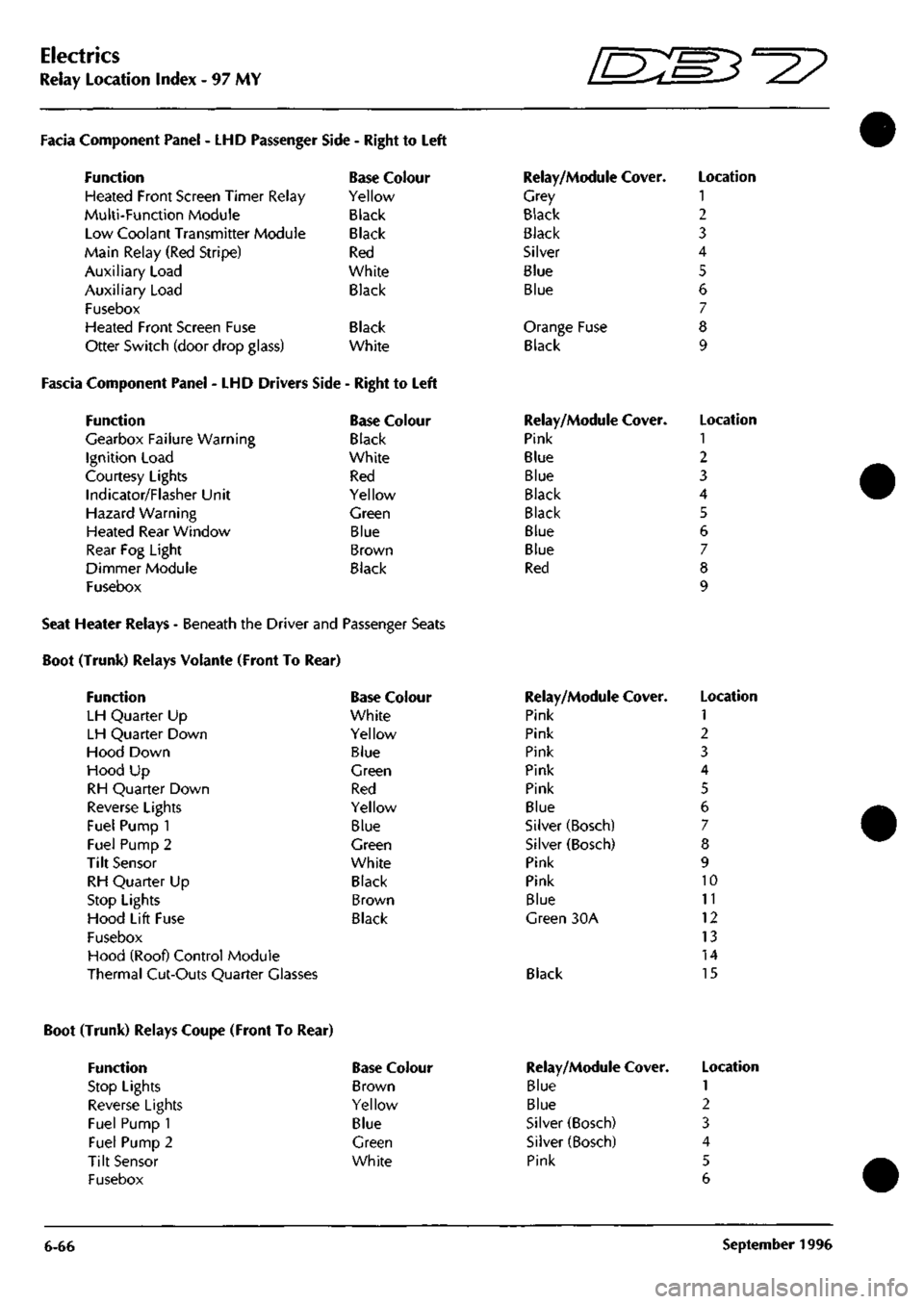
Relay Location Index - 97 MY
D^^
Facia Component Panel
- LHD
Passenger
Function
Heated Front Screen Timer Relay
Multi-Function Module
Low Coolant Transmitter Module
Main Relay (Red Stripe)
Auxiliary Load
Auxiliary Load
Fusebox
Heated Front Screen Fuse
Otter Switch (door drop glass)
Side
-
Right
to
Left
Base Colour
Yellow
Black
Black
Red
White
Black
Black
White
Fascia Component Panel
- LHD
Drivers Side
-
Right
to
Left
Function
Gearbox Failure Warning
Ignition Load
Courtesy Lights
Indicator/Flasher Unit
Hazard Warning
Heated Rear Window
Rear
Fog
Light
Dimmer Module
Fusebox
Base Colour
Black
White
Red
Yellow
Green
Blue
Brown
Black
Relay/Module Cover.
Grey
Black
Black
Silver
Blue
Blue
Orange Fuse
Black
Relay/Module Cover.
Pink
Blue
Blue
Black
Black
Blue
Blue
Red
Location
1
2
3
4
5
6
7
8
9
Location
1
2
3
4
5
6
7
8
9
Seat Heater Relays - Beneath the Driver and Passenger Seats
Boot (Trunk) Relays Volante (Front To Rear)
Function
LH Quarter
Up
LH Quarter Down
Hood Down
Hood
Up
RH Quarter Down
Reverse Lights
Fuel Pump
1
Fuel Pump
2
Tilt Sensor
RH Quarter
Up
Stop Lights
Hood Lift Fuse
Fusebox
Hood (Roof) Control Module
Thermal Cut-Outs Quarter Glasses
Base Colour
White
Yellow
Blue
Green
Red
Yellow
Blue
Green
White
Black
Brown
Black
Relay/Module Cover.
Pink
Pink
Pink
Pink
Pink
Blue
Silver (Bosch)
Silver (Bosch)
Pink
Pink
Blue
Green
30A
Black
Location
1
2
3
4
5
6
7
8
9
10
11
12
13
14
15
Boot (Trunk) Relays Coupe (Front To Rear)
Function
Stop Lights
Reverse Lights
Fuel Pump 1
Fuel Pump 2
Tilt Sensor
Fusebox
Base Colour
Brown
Yellow
Blue
Green
White
6-66
Relay/Module
Blue
Blue
Silver (Bosch)
Silver (Bosch)
Pink
Cover. Location
1
2
3
4
5
6
September
1996
Page 132 of 421
^^?
Electrics
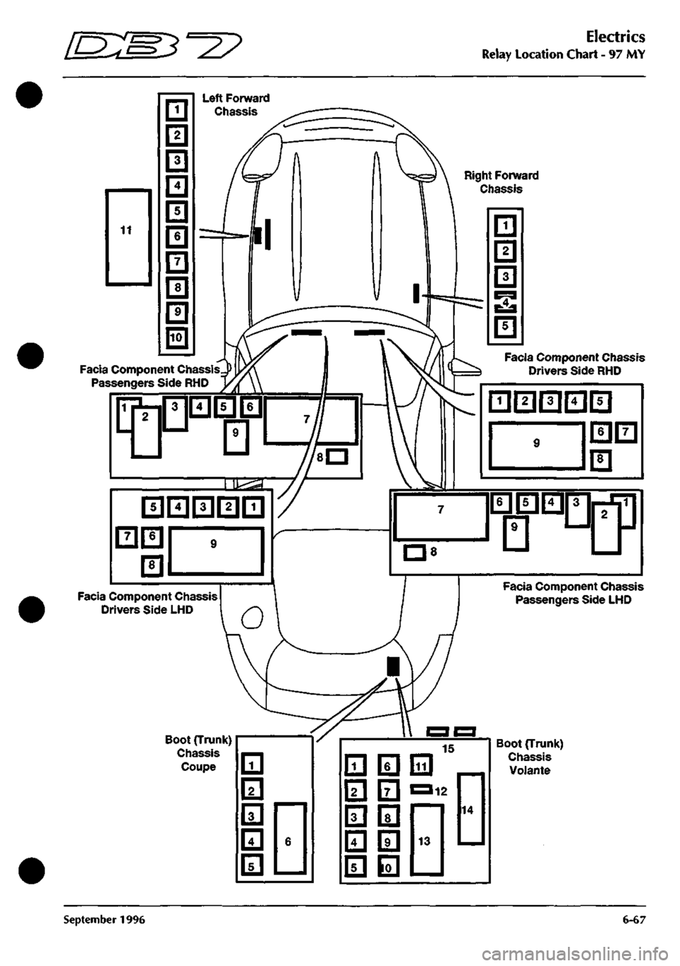
Relay Location Chart - 97 MY
Right Forward
Chassis
Facia Component Chassis
Passengers Side RHD
Facia Component Chassis
Drivers Side LliD
Boot (Trunk)
Chassis
Coupe 111
I2I
131
m
fsl
6
Boot (Trunlt)
Chassis
VoJante
September 1996 6-67
Page 333 of 421
Air Conditioning Repair Procedures
Air-Conditioning Unit Renew ^^?
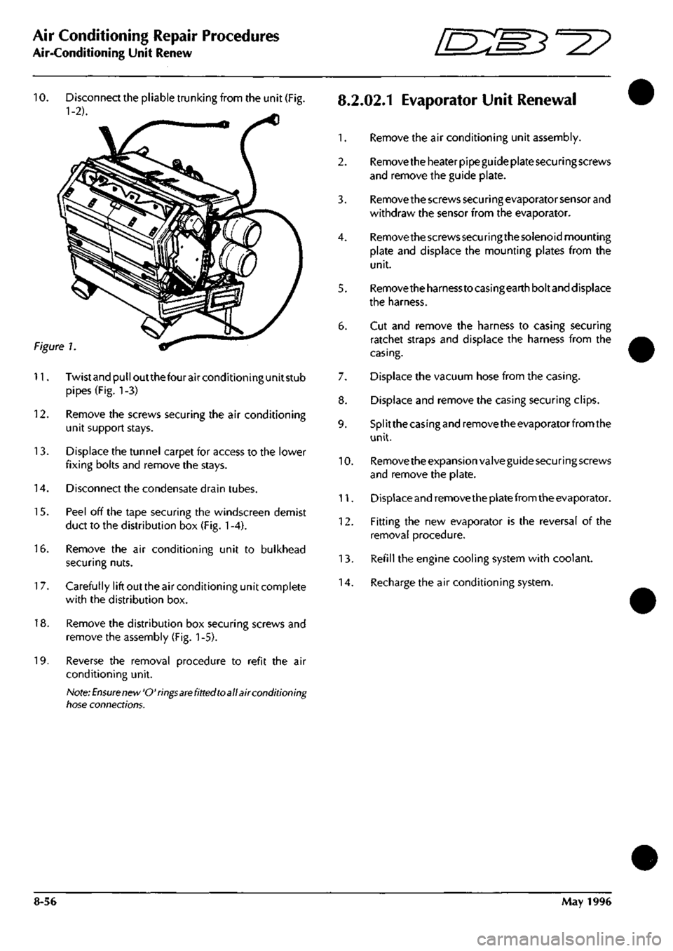
10.
Disconnect the pliable trunking from the unit (Fig.
8.2.02.1
EvaporatOr Unit Renewal
1-2). ^
1.
Remove the air conditioning unit assembly.
2.
Remove the heater pipe guide plate securing screws
and remove the guide plate.
3. Remove the screws secu ri ng evaporator sensor and
withdraw the sensor from the evaporator.
4.
Remove the screws securing the solenoid mounting
plate and displace the mounting plates from the
unit.
5. Removetheharnesstocasingearthboltand displace
the harness.
6. Cut and remove the harness to casing securing
ratchet straps and displace the harness from the
casing.
7. Displace the vacuum hose from the casing.
8. Displace and remove the casing securing clips.
9. Splitthecasingandremovetheevaporatorfromthe
unit.
10.
Remove the expansion valve guide securing screws
and remove the plate.
11.
Displace and remove the plate from the evaporator.
12.
Fitting the new evaporator is the reversal of the
removal procedure.
13.
Refill the engine cooling system with coolant.
14.
Recharge the air conditioning system.
Figure 1
11.
Twistandpulloutthefourairconditioningunitstub
pipes (Fig. 1-3)
12.
Remove the screws securing the air conditioning
unit support stays.
13.
Displace the tunnel carpet for access to the lower
fixing bolts and remove the stays.
14.
Disconnect the condensate drain tubes.
15.
Peel off the tape securing the windscreen demist
duct to the distribution box (Fig.
1
-4).
16.
Remove the air conditioning unit to bulkhead
securing nuts.
1
7. Carefully lift out the air conditioning unit complete
with the distribution box.
18.
Remove the distribution box securing screws and
remove the assembly (Fig.
1
-5).
19.
Reverse the removal procedure to refit the air
conditioning unit.
Note:
Ensure new'O'rings
are
fitted toall air conditioning
tiose connections.
8-56 May 1996
Page 336 of 421
'nzm^=2?
Air Conditioning Repair Procedures
Blower Motor Renewal
8.2.07.1 Ambient Temperature Sensor
Renew
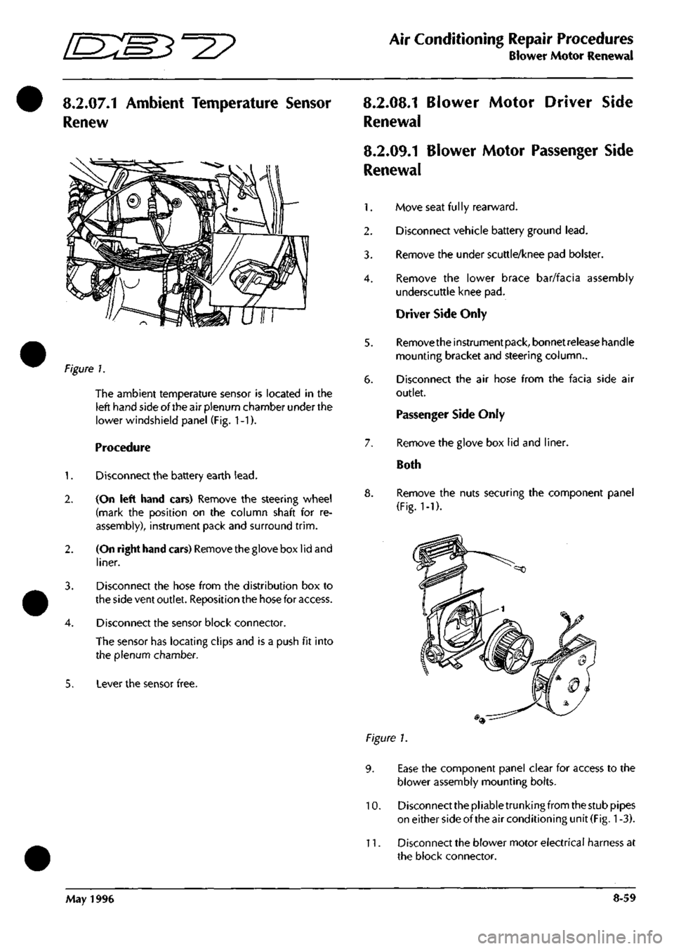
?\gure
1.
The ambient temperature sensor is located in the
left hand side of the air plenum chamber under the
lower windshield panel (Fig. 1-1).
Procedure
1.
Disconnect the battery earth
lead.
2.
(On left hand cars) Remove the steering wheel
(mark the position on the column shaft for re
assembly), instrument pack and surround
trim.
2.
(On right hand cars) Removethegloveboxlidand
liner.
3. Disconnect the hose from the distribution box to
the side vent outlet. Reposition the hose for access.
4.
Disconnect the sensor block connector.
The sensor has locating clips and is a push fit into
the plenum chamber.
5. Lever the sensor free.
8.2.08.1 Blower Motor Driver Side
Renewal
8.2.09.1 Blower Motor Passenger Side
Renewal
1.
Move seat
fu 1
ly rearward.
2.
Disconnect vehicle battery ground
lead.
3. Remove the under scuttle/knee pad bolster.
4.
Remove the lower brace bar/facia assembly
underscuttle knee pad.
Driver Side Only
5. Removetheinstrumentpack, bonnetreieasehandle
mounting bracket and steering column..
6. Disconnect the air hose from the facia side air
outlet.
Passenger Side Only
7. Remove the glove box lid and liner.
Both
8. Remove the nuts securing the component panel
(Fig.
1-1).
Figure 1.
9. Ease the component panel clear for access to the
blower assembly mounting bolts.
10.
Disconnect the pliable trunking from the stub pipes
on either side of the air conditioning unit
(Fig.
1
-3).
11.
Disconnect the blower motor electrical harness at
the block connector.
May 1996 8-59