service ASTON MARTIN DB7 1997 Owner's Guide
[x] Cancel search | Manufacturer: ASTON MARTIN, Model Year: 1997, Model line: DB7, Model: ASTON MARTIN DB7 1997Pages: 421, PDF Size: 9.31 MB
Page 296 of 421
^2?
Air Conditioning
Electronic Control Module
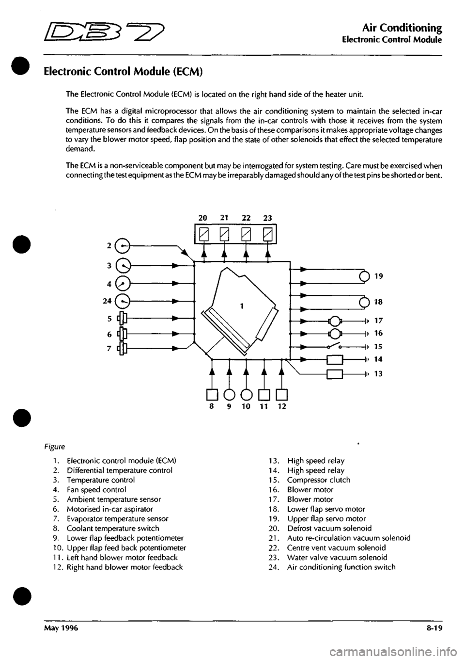
Electronic Control Module (ECM)
The Electronic Control Module (ECM) is located on the right hand side of the heater unit.
The ECM has a digital microprocessor that allows the air conditioning system to maintain the selected in-car
conditions. To do this it compares the signals from the in-car controls with those it receives from the system
temperature sensors and feedback
devices.
On the basis of these comparisons it makes appropriate voltage changes
to vary the blower motor
speed,
flap position and the state of other solenoids that effect the selected temperature
demand.
The ECM is a non-serviceable component but may be interrogated for system
testing.
Care must be exercised when
connecting
the test
equipment
as the ECM
may
be
irreparably
damaged
should any ofthe
test
pins
be
shorted or bent.
20 21 22 23
Q
A / A \/
Em
10 11
1.
Electronic control module (ECM)
2.
Differential temperature control
3. Temperature control
4.
Fan speed control
5. Ambient temperature sensor
6. Motorised in-car aspirator
7. Evaporator temperature sensor
8. Coolant temperature switch
9. Lower flap feedback potentiometer
10.
Upper flap feed back potentiometer
11.
Left hand blower motor feedback
12.
Right hand blower motor feedback
13.
High speed relay
14.
High speed relay
15.
Compressor clutch
16.
Blower motor
17.
Blower motor
18.
Lower flap servo motor
19.
LIpper flap servo motor
20.
Defrost vacuum solenoid
21.
Auto re-circulation vacuum solenoid
22.
Centre vent vacuum solenoid
23.
Water valve vacuum solenoid
24.
Air conditioning function switch
May 1996 8-19
Page 314 of 421
^?
Air Conditioning
Sanden Compressor SD7H15
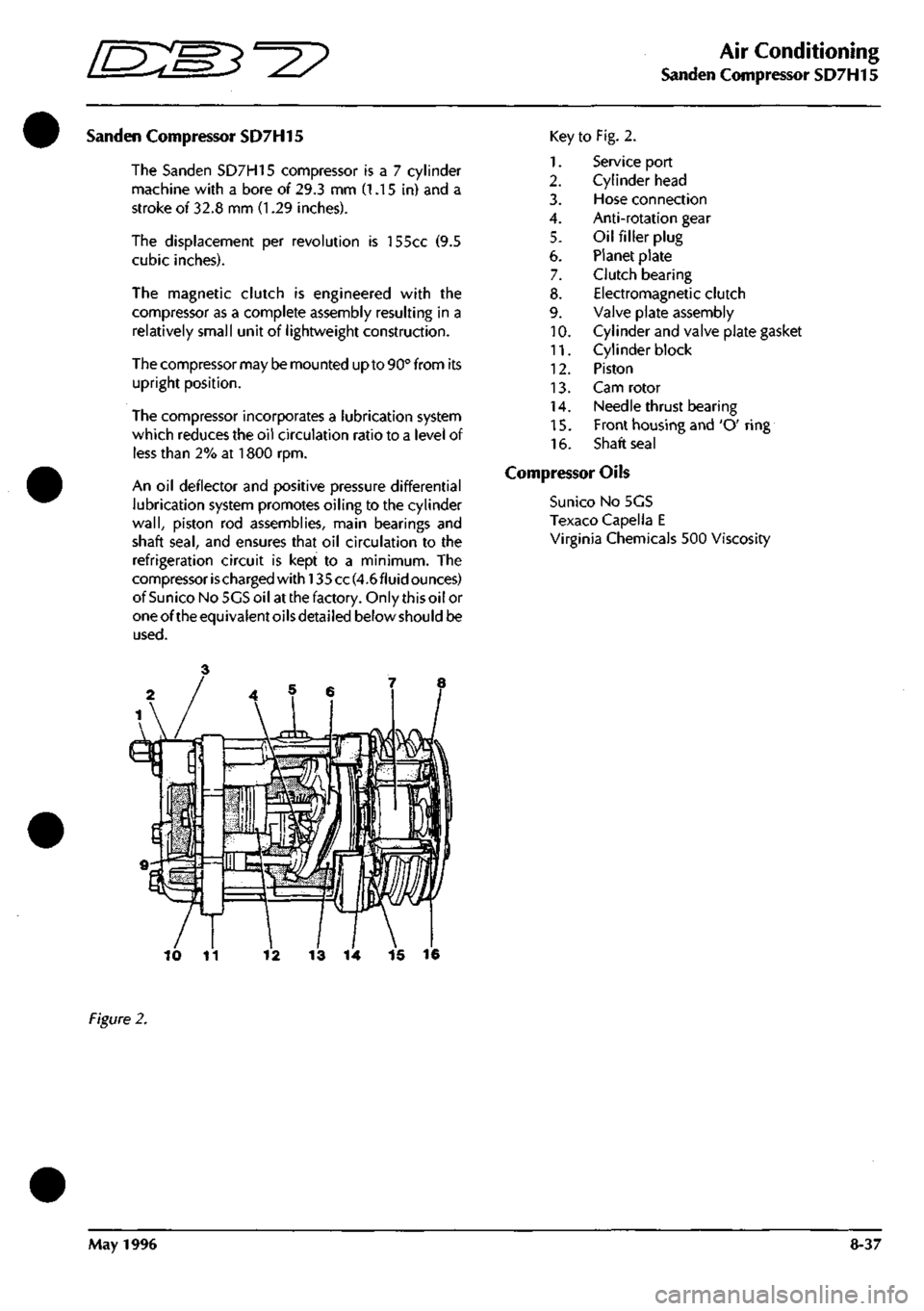
Sanden Compressor SD7H15
The Sanden SD7H15 compressor
is a 7
cylinder
machine with
a
bore
of
29.3
mm (1.15 in) and a
stroke
of
32.8
mm (1.29
inches).
The displacement
per
revolution
is
155cc
(9.5
cubic inches).
The magnetic clutch
is
engineered with
the
compressor
as a
complete assembly resulting
in a
relatively small unit
of
lightweight construction.
The compressor may be mounted up to 90° from
its
upright position.
The compressor incorporates
a
lubrication system
which reduces the
oil
circulation ratio
to a
level
of
less than
2% at 1800 rpm.
An
oil
deflector
and
positive pressure differential
lubrication system promotes oiling
to the
cylinder
wall,
piston
rod
assemblies, main bearings
and
shaft
seal,
and
ensures that
oil
circulation
to the
refrigeration circuit
is
kept
to a
minimum.
The
compressor ischarged
with!
35 cc(4.6fluid ounces)
ofSunico NoSGSoil at the factory. Only this oil
or
oneoftheequivalentoilsdetailed below should
be
used.
Key
1.
2.
3.
4.
5.
6.
7.
8.
9.
10.
11.
12.
13.
14.
15.
16.
to Fig. 2.
Service port
Cylinder head
Hose connection
Anti-rotation gear
Oil filler plug
Planet plate
Clutch bearing
Electromagnetic clutch
Valve plate assembly
Cylinder and valve plate gasket
Cylinder block
Piston
Cam rotor
Needle thrust bearing
Front housing and 'O' ring
Shaft seal
Compressor Oils
Suni
CO
No 5GS
Texaco Capella E
Virginia Chemicals 500 Viscosity
13
14 15 16
Figure
2.
May
1996
8-37
Page 315 of 421
Air Conditioning
Manifold Gauge Set 5=2?
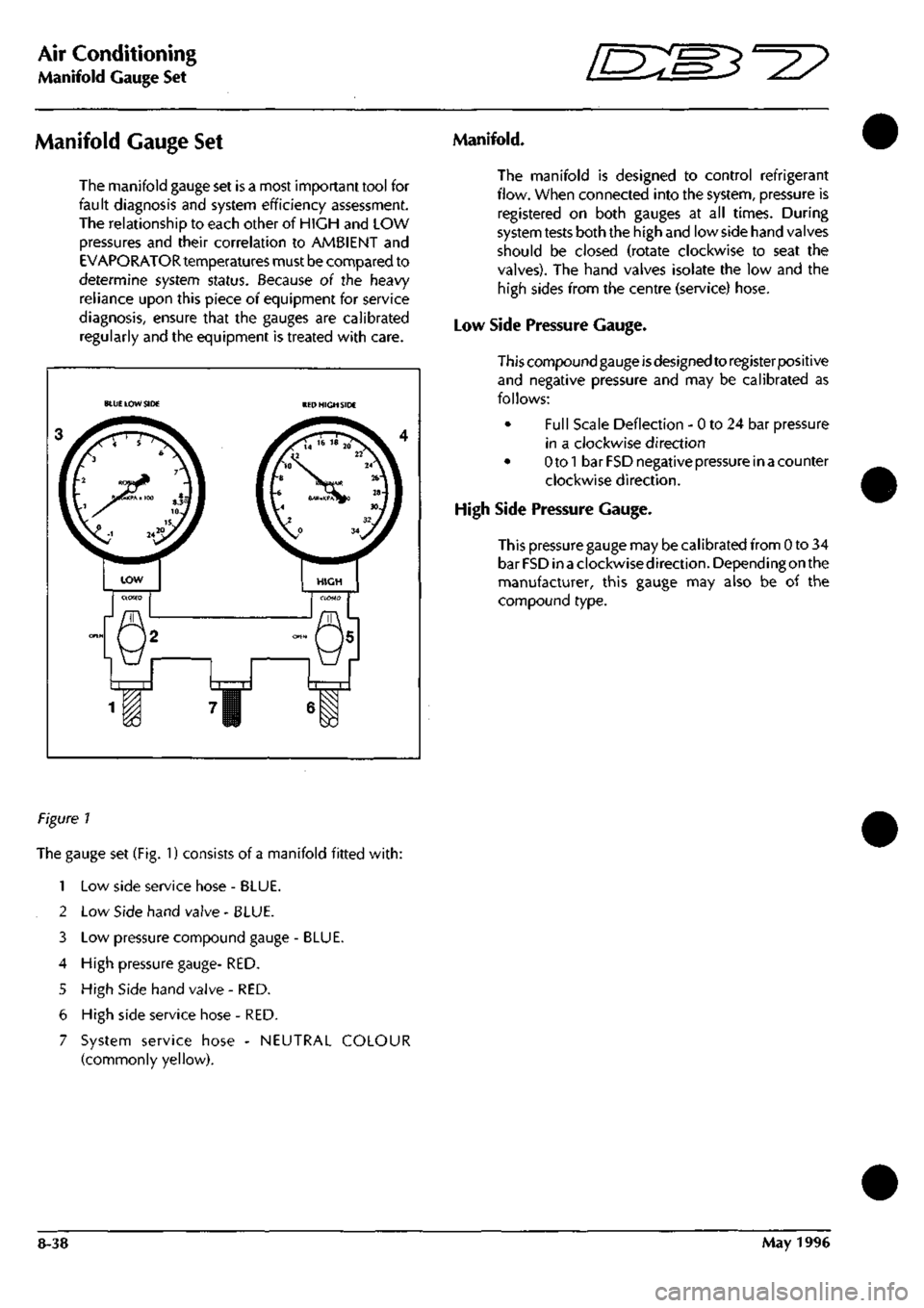
Manifold Gauge Set
The manifold gauge set is a most important tool for
fault diagnosis and system efficiency assessment.
The relationship to each other of HIGH and LOW
pressures and their correlation to AMBIENT and
EVAPORATOR temperatures must be compared to
determine system status. Because oi the heavy
reliance upon this piece of equipment for service
diagnosis, ensure that the gauges are calibrated
regularly and the equipment is treated with care.
BLUE LOW SIDE RED HIGH SIDE
LOW
m
m
Manifold.
The manifold is designed to control refrigerant
flow. When connected into the system, pressure is
registered on both gauges at all times. During
system tests both the high and low side hand valves
should be closed (rotate clockwise to seat the
valves). The hand valves isolate the low and the
high sides from the centre (service) hose.
Low Side Pressure Gauge.
This compound gauge
is
designed to register positive
and negative pressure and may be calibrated as
follows:
• Full Scale Deflection - 0 to 24 bar pressure
in a clockwise direction
• Otol bar FSD negative pressure in a counter
clockwise direction.
High Side Pressure Gauge.
This pressure gauge may be calibrated from 0 to 34
bar FSD inaclockwisedirection. Depending on the
manufacturer, this gauge may also be of the
compound type.
Figure 1
The gauge set (Fig. 1) consists of a manifold fitted
with:
1 Low side service hose - BLUE.
2 Low Side hand valve - BLUE.
3 Low pressure compound gauge - BLUE.
4 High pressure gauge- RED.
5 High Side hand valve - RED.
6 High side service hose - RED.
7 System service hose - NEUTRAL COLOUR
(commonly yellow).
8-38 May 1996
Page 352 of 421
^?
The Aston Martin Lagonda Diagnostic System
Contents
Installation Instructions
Introduaion 9-2
The Aston Martin Diagnostic System 9-2
Diagnostic System Cables 9-5
Base Station Installation 9-8
Problem Solving 9-16
Service Centres 9-21
Service and Maintenance 9-22
Technical Specifications 9-24
Operating Instructions
The Aston Martin Lagonda Diagnostic System 9-27
Software 9-29
Cable Setup 9-31
Diagnostic Sockets - 97 MY 9-31
Establishing Communications 9-32
System Menu Selections 9-32
PDU Use 9-32
Engine Diagnostics - 97 MY 9-33
Transmission Diagnostics 9-40
Climate Control Diagnostics 9-43
Anti-Lock Brakes Diagnostics 9-43
Passive Anti-Theft (PATS) Diagnostics 9-44
Airbag System Diagnostics 9-45
Seat Belt Pretensioner Diagnostics 9-47
Print Facility 9-49
Digital Multimeter 9-50
Diagnostic Trouble Codes 9-53
Datalogger 9-55
Datalogger Example 9-63
Training 9-66
OBD II Scan Tool 9-66
System Self Test 9-69
The Asterisk (*) Menu 9-69
System Setup 9-70
May 1996 9-1
Page 353 of 421
The Aston Martin Lagonda Diagnostic System
Installation Instructions E:MB^^?
Introduction The Aston Martin Diagnostic System
This guide contains instructions for the installation
of the Portable Diagnostic Unit hardware in Aston
Martin Dealer workshops. To achieve maxinnum
benefit from the system, please follow the
instructions carefully. The following System
Diagram shows the principal system components
and panel details.
This introduction briefly describes the system and
its capabilities. This is followed by the Installation
and Power-Up procedures which give detailed
instruaions on how to start the system and access
the self-contained Interactive
Training
Programme.
The subsequent sections detail the fault diagnosis
and maintenance procedures.
WARNING:
The equipment must
only
be used by
trained
personnel.
Care should
be taken to use the
equipment in accordance with the operating
procedures.
Observe
all safety
warnings
in this
guide.
If any part of
the system is damaged do not
use it. Call your local CenRad
Service
Centre
immediately
for a
substitute
part.
Refer to
'Parts
Ordering'.
The Aston Martin Diagnostic System is a new
generation diagnostic
tool
which fulfils
a
number of
functions in aiding the technician to quickly and
accurately locate faults. The heart of the system is
the Portable Diagnostic
Unit,
a
lightweight powerful
computer/measurement system providing a step-
by-step user friendly interface for the technician.
PDU functions include:
Data Logger - The ability to monitor and record
control module signals even whilst the vehicle is
being driven.
On-Line Help-Containing detailed descriptions in
the
operation
ofthevehicleselectroniccomponents.
Vehicle Setup - The ability to setup various
adjustable parameters to their optimum settings.
Diagnostic Trouble Codes - The ability to extract
recorded fault information from the DB7's control
modules.
Each of
these
funaions is described in detail in the
PDU Users Guide.
WARNING: If
the system is used to measure high
voltages,
these voltages can appear on the pins of
other
connectors in
the
system.
Ensure
that socket
covers
are
fitted
on
unused
sockets.
Ensure
that all
connections
are
made
prior to
applying the high
voltage to
the
probes.
Do not
leave the equipment
unattended
in
this
state.
The maximum
voltage
that may be applied
between the
test
probes is 150
volts
AC or DC.
Radio Interference Statements
This digital apparatus does not exceed the Class A
limits for radio noiseemissionsfromdigital apparatus
as set
out
in
the radio interference regulations of the
Canadian Department of Communications.
This equipment has been tested and found to
comply with the limits for Class A digital device
pursuant to part 15 of the Federal Communications
Commission (FCC) rules. However, operation in
close proximity to domestic communication
equipment may cause interference. It is the
responsibility of the user to avoid or correct this
condition.
9-2 May 1996
Page 361 of 421
The Aston Martin Lagonda Diagnostic System
Installation Instructions
[ES^'^?
Powering-Up the Base Station
When first operating the System or when first using
a PDU fitted with substitute batteries, it will take up
to36 hourstoachievefull charge. Inthemeantime,
the PDU can be used whilst connected to the base
station or to the vehicle battery.
Vi/\RNmGS:
When using the system equipment, basic safety
precautions should always be followed, including:
Carefully read and follow all instructions.
Care should be taken as burns can occur from
touching hot parts.
Do not operate the appliance with a damaged
mains lead or if the appliance has been dropped or
damaged. Call your local GenRad Service Centre
immediately for a substitute
part.
Do not let the mains lead hang over the
edge
of the
table, bench or counter or come into contact with
hot manifolds or moving fan blades.
The Aston Martin Portable Diagnostic Unit
is
fitted with an
auto switching power supply suitable for voltage supplies
of 100 - 240 VAC 50 - 60 Hz. You need only check that
the power cord connector is of the correct type for your
power outlets.
1.
Connect the mains lead to the mains outlet.
2.
Check that the green indicator lamp above the base
station door is illuminated. If the green lamp does
not come on, see the problem solving section for
advice.
3. After a few seconds, during which the electronics
module completes its self-test, the red OK indicator
lamp should illuminate. If the red lamp does not
come on, see the problem solving section for
advice.
4.
Allow the base station electronics module to reach
working temperature. This will take approximately
BOminutes, after which time the base station will be
ready to accept the software on CD-ROM.
5. Slide the PDU into its carrying case and place the
associated cables and probes in the carrying case
compartments.
6. Place the carrying case onto the base station at the
far left side (Fig 5). This is the normal place for
charging the battery, loading software and storing
the PDU. Note that it is retained by raised retaining
blocks which fit inside the recesses under the
carrying cases (Fig 5).
7. Remove the protective coverfromthe PDU interface
panel socket (Fig
1
-7.6)
8. Usingthe PDU to base station cable (0064) connect
panel socket 6 to the base station left socket (Fig
1
-
19).
The indicator lamp will glow orange during
fast charge and yellow during trickle charging.
9. A second PDU can be fitted on the central position
on the base station and may be connected to the
right charging socket using a second cable (0064).
Note that both units may be charged simultaneously
but software may only be loaded from CD-ROM
using the left base station socket.
Figure 5. Normal PDU position
9-10 May 1996
Page 366 of 421

r^ ' ^ ^ The Aston Martin Lagonda Diagnostic System
Installation Instructions
Finishing the Test
When data analysis is finished, switch off the PDU
and disconnect it from the vehicle. Store the PDU
and cables in the carrying case and refit the case to
the base station.
Connect the PDU to the base station using cable
0064.
The base station will keep the PDU batteries
fully charged at all times (Fig 15).
Figure 15. PDU connected for recharging
Care of the Equipment
CAUTION: With the exception of those parts
referred to in the Servicing and Maintenance
section, there are no user serviceable parts. All
servicing must be carried out by GenRad Service
Centres.
Switch offthe power before cleaningtheequipment.
The Aston Martin Diagnostic System should only
be cleaned using a non-abrasive, mild cleaning
agent. Dust and other particles should be lightly
brushed from the surface before
cleaning.
Cleaning
agent should be applied to a soft lint-free cleaning
cloth and never directly to the unit. Do not soak the
cleaning cloth and take care not to allow cleaning
fluid to enter connectors.
CAUTION: Ifany liquid is spilt on theequipment,
switch off immediately.
Ensure
that the equipment
has
dried out completely before operating it again,
especially in connectors where fluid can lodge.
May 1996 9-15
Page 367 of 421
The Aston Martin Lagonda Diagnostic System
Installation Instructions ^7
Problem Solving
CAUTION: If any part of the
system
is damaged, do not use it. Call your local GenRad Service Centre immediately for
a substitute
part.
Refer to 'Parts Ordering'.
CAUTION: With the exception of
those
parts referred to in the Servicing and Maintenance section, there are no user
serviceable parts. All servicing must be carried out by GenRad Service Centres.
PDU Self-Test
The system self test routine should be run periodically even if there are no apparent problems with the system.
Running the system self-test will identify any problems before they impact on productivity.
If it is suspected that the system is operating incorrectly, run the PDU system self test option on the main menu).
If the system self test will not run, or the PDU will not switch on, the instructions in this section must be followed
carefully.
If one of the fol lowing test steps advises you to order or fit a new part, make a note of the test step, part number and
description. Then follow the parts ordering procedure later in this section.
Stepi
Connect the mains power to the base station. Is the green base station indicator illuminated?
YES - Go to step 4
NO - Go to step 2
Step 2
Check the mains supply, then check the mains
lead.
Is
the mains lead faulty?
YES - Renew the mains
lead.
NO - Go to step 3
Step 3
Remove the electronic module from the base station.
Using a small screwdriver, open the fuse drawer below the power socket on the rear of the module (Fig 16). Remove
the fuse and fit the spare fuse. The fuse must be lEC 127 approved ceramic type 250V 2A (T). Re-install the module
into the base station, power up the system. Is the base station green indicator illuminated?
YES - The fuse was faulty
NO - Renew the electronic module (0019)
Figure 16. Electronic Module Fuse Replacement
9-16 May 1996
Page 370 of 421
^^
The Aston Martin Lagonda Diagnostic System
Installation Instructions
Step 16
Observe the display screen. Is the screen displaying
either of the symbols shown in Fig 19?
YES - Remove the CD caddy and check the CD-ROM.
Re-install the CD-ROM. Go to step 13.
NO - Co to step 19
Figure 19. Reload the CD and retry
Step 17
Connect the PDU to the base station top left connector using the second PDU to base station cable (0064) (Fig 34).
Is the screen displaying the symbol shown in Fig 15?
YES - Go to step 18
NO - The first PDU to base station cable is faulty, renew the cable (0064)
Step 18
Connect the PDU to the VIA using cable (0030) and connect the VIA to the VBA using cable (0028). Connect the
VBA to a charged battery. Does the VIA panel indicator flash for more than 5 seconds after pressing the 'tick'
icon.
YES - Renew the electronic module (0019)
NO - Renew the PDU (001 7)
Step 19
Observe the screen display. Is the screen displaying the
symbol shown in Fig 20?
YES - During the data transfer, the connection was lost.
Check to see if the cable connections are intact, if not,
reconnect and go back to step 13.
NO - Go to step 20
Figure 20. Data transfer connection lost
Step 20
Observe the screen display, is the language selection
screen displayed (Fig 21)?
YES - Try to select a language, go to step 21
NO-Call your local GenRad Service Centre for advice.
(^G?) English
Figure 2
7.
Language selection screen
May 1996 9-19
Page 371 of 421

The Aston Martin Lagonda Diagnostic System
Installation Instructions =27
step 21
Observe the screen display. Is the system loading from the CD-ROM?
YES - Go to step 13.
NO - Renew the PDU (001 7).
Parts Ordering
Before calling GenRad, it is essential that the system self test is run from the main menu. If the system self test will
not run or the PDU does not switch on, follow the Problem Solving procedures.
The system self test option will identify any fau It and display a fault code on the PDU screen. This fault code number
must be recorded. When in contact with your local GenRad Service Centre, they will require this number in order
to send the correct substitute parts.
Before calling the GenRad Service Centre, please have the following information available.
Dealer Name and Address
Name of the contact at that address
PDU Serial Number (base station LHS - Fig 22)
Fault Code, Component Name and Serial Number as given on the PDU screen during self test.
Ifthe system self test will not run, GenRad will require the name and part number ofthe component identified during
he Problem Solving Procedures.
Figure 22. Diagnostic System Serial Number
9-20 May 1996