ignition ASTON MARTIN DB7 1997 Repair Manual
[x] Cancel search | Manufacturer: ASTON MARTIN, Model Year: 1997, Model line: DB7, Model: ASTON MARTIN DB7 1997Pages: 421, PDF Size: 9.31 MB
Page 271 of 421
Body and Trim
Rear Quarter Window Lift Motor '^^
9.1.01.5 - Rear Quarter Window Lift
Motor - Right Hand
Procedure
1.
Move the front seat forward to gain access.
2.
Switch on the ignition, release the roof locking
latches and lower the roof. Switch off the ignition.
3. Remove the rear seat squab and cushion. Remove
the rear quarter trim panel.
4.
Disconnect the window motor feed wires.
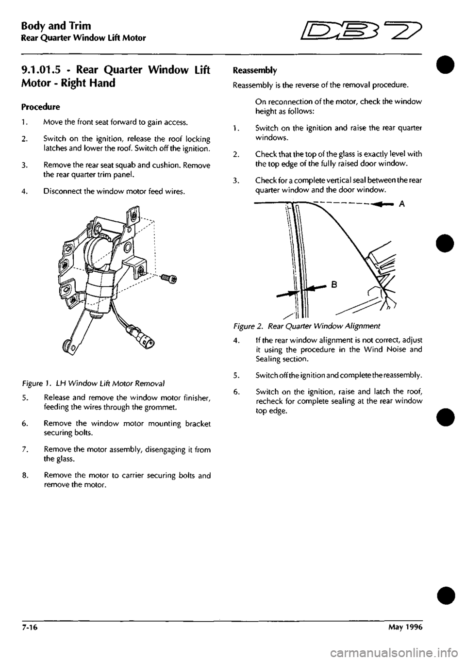
Figure 1. LH Window Lift Motor Removal
5. Release and remove the window motor finisher,
feeding the wires through the grommet.
6. Remove the window motor mounting bracket
securing bolts.
7. Remove the motor assembly, disengaging it from
the glass.
8. Remove the motor to carrier securing bolts and
remove the motor.
Reassembly
Reassembly is the reverse of the removal procedure.
On reconnection of the motor, check the window
height as follows:
1.
Switch on the ignition and raise the rear quarter
windows.
2.
Check that the top of the glass is exactly level with
the top edge of the fully raised door window.
3. Check for a complete vertical seal between the rear
quarter window and the door window.
A
Figure 2. Rear Quarter Window Alignment
4. If the rear window alignment is not correct, adjust
it using the procedure in the Wind Noise and
Sealing section.
5. Switch offthe ignition and complete the reassembly.
6. Switch on the ignition, raise and latch the roof,
recheck for complete sealing at the rear window
top edge.
7-16 May 1996
Page 288 of 421
^7
Air Conditioning
Temperature Distribution System
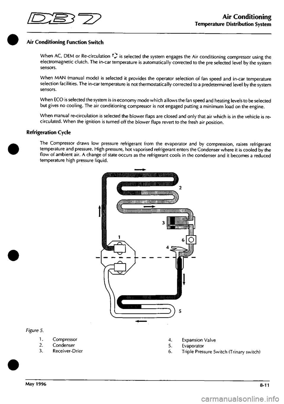
Air Conditioning Function Switch
When AC, DEM or Re-circulation ^v is selected the system engages the Air conditioning compressor using the
electromagnetic clutch. The in-car temperature is automatically corrected to the pre selected level by the system
sensors.
When MAN (manual mode) is selected it provides the operator selection of fan speed and in-car temperature
selection facilities. The in-car temperature is not thermostatically corrected to a predetermined level by the system
sensors.
When ECO is selected the system is in economy mode which allows the fan speed and heating levels to be selected
but gives no cooling. The air conditioning compressor is not engaged putting a minimum load on the engine.
When manual re-circulation is selected the blower flaps are closed and only that air which is in the vehicle is re
circulated.
When the ignition is turned off the blower flaps revert to the fresh air position.
Refrigeration Cycle
The Compressor draws low pressure refrigerant from the evaporator and by compression, raises refrigerant
temperature and pressure. High pressure, hot vaporised refrigerant enters the Condenser where it is cooled by the
flow of ambient air. A change of state occurs as the refrigerant cools in the condenser and it becomes a reduced
temperature high pressure liquid.
Figure 5.
1.
2.
3.
Compressor
Condenser
Receiver-Drier
4.
Expansion Valve
5. Evaporator
6. Triple Pressure Switch (Trinary switch)
May 1996 8-11
Page 292 of 421
Air Conditioning
Functional Check
Functional Check
This functional check procedure is provided as a simple system validation and is structured to augment the Portable
Diagnostic Unit (PDU).
Stage 1 (Cold engine only, if not proceed to Stage 2)
Procedure Normal System Reaction
1.
Ignition ON
Select MIN temperature, MAN, speed 3, Mid face.
(Engine Stationary) Fans Start
2.
Select MAX temperature Fans continue to run
3. Ignition OFF
Select MAX temperature and defrost
Ignition ON Fans start at maximum speed
4.
Select fan speed
1
Fan speed adjusts accordingly - system OK
Stage 2
Procedure Normal System Reaction
1.
Start up engine and warm up
Select fan speed 1, MAN, MAX TEMPERATURE
and mid face
2.
Open all vents Fans start after 3 seconds
2.
Select fan speed 2 Fan speed increases then stabilises
3. Select fan speed 3 Fan speed increases then stabilises
4.
Select defrost Fan speed steady at high
All air at screen and dash end
5. Re-select fan speed 1
Select AUX ignition key position
6. Slowly select MIN temperature Solenoids switch 1. centre vent
2.
water valve
3. Re-circulation
7. Re-select MID temperature
8. Select DEM Solenoid clicks
Air at screen
9. Select manual re-circulation Solenoid click
10.
Check flap for position
11.
Run Engine to normal temperature
12.
Select: MAN, 3/4 MAX heat and fan speed 2 Air from door vents
cool,
air temp from foot outlet slightly warm
13.
Select MAX temperature and air differential to hot face All vent outlets max temp except screen vent
14.
Select temperature
approx. 1/4 MAX heat and mid face level Cool air from centre vents
15.
Select MIN temperature Blower flaps at re-circulation position
All outlets blowing cold air except screen vent
May 1996 8-15
Page 297 of 421
Air Conditioning
Electronic Control Module r^^?
Description
The ECM (Fig 1) controls the air conditioning
system so that selected temperaturesare maintained.
It cannot be repaired but input and output signals
can be measured, using the PDU, for diagnostic
purposes.
Input-Output Voltage Signals
The following voltage signal levels are input and
output from the ECM:
Digital input levels:
Low
High
Analogue input levels:
General
Blend Flap Potentiometer
Digital output levels
Relays On
Off
Vacuum manifold Pull-in
Drop-out
Analogue output levels
Blend Flap Servo Motors
Blower Motors
0.16 to 1.1V
3.70 to 4.50V
0 to 0.2885 V
0 to 5.0V
8.0V
1.0 to 5.0V
5.6V (typical)
3.5V (typical)
0.5 to 6.5V
0.5 to 2.5V
figure 1.
The ECM
is
turned on when the ignition
is
turned on
to auxiliary position 1. its operating range is 13.5-
14.2 volts.
The ECM power unit supplies +5 volts for the
temperature sensors, feedback potentiometers and
high speed relays.
An integrated circuit protects the ECM against
reversed polarity and voltage surges.
Caution: Take care when connecting test equipment. If
test pins are allowed to be shorted together, to
ground or to positive supplies the ECM will be
damaged.
8-20 May 1996
Page 301 of 421

Air Conditioning
In Car Controls ^2?
Evaporator Sensor
The evaporator sensor allov^^s the ECM to monitor
the temperature ofthe refrigerant in the evaporator
core continuously. When the temperature falls
below 0°C the ECM de-energises the compressor's
electromagnetic clutch and prevents refrigerant
from flowing through the system. The clutch is re
engaged when the temperature rises.
Motorised In-Car Aspirated Sensor
The motorised aspirator (Fig. 8), which is fitted to
the passenger side facia underscuttle panel,
incorporates a motor driven fan (Fig. 8-1) that
draws air continuously over the in car temperature
sensor (Fig. 8-2).
Figure 8.
Key
1.
2.
3.
4.
5.
to Fig. 8
Motor
Sensor
Fan
Connector SCAO07
Connector SAC030
The motor (Fig. 8-1) is supplied, independently of
the air conditioning
system,
from the ign ition switch
(position 2). Its operating voltage range is 13.5 to
14.2 volts. Maximum current is 120 mA. The sensor
(Fig.
8-2) has a temperature operating range of -
30°C to +85°C. It is fed with 5 volts from the ECM
(pin 43), while the sensing voltage
is
supplied to pin
4 ofthe ECM. At 0°C the sensing voltage is 2.732V
± 0.002V. The rate of change of sensing voltage is
0.01 V± 0.002V per 1°C.
LC/0
0^5
U
Figure 9.
Key to Fig. 9
1.
Ignition switched supply to motor
2.
+5V supply to sensor from pin 43 of ECM
3. Sensor voltage output to pin 10 of ECM
4.
Sensor earth-ground to pin 4 of ECM
5. Motor earth-ground
A. Motor
B. Sensor
Ambient Temperature Sensor
An ambient temperature sensor (Fig. 10-1) is fitted
in the plenum air intake to provide the ECM with
information on the temperature ofthe air entering
the air conditioning unit and so offset the in-car
temperature at extremes of ambient. The voltage
signal output from the sensor is proportional to the
temperature of the surrounding air. The sensor
temperature range is -30°C to 85°C. At 0°C the
output ofthe sensor is 2.732V ± 0.005V. The rate
of change is + 0.01 V ± 0.002V per
1
°C.
Figure 10.
Key to Fig. 10
1.
Ambient temperature sensor
2.
+5 volts from ECM Pin 43
3. Sensing signal to ECM Pin 34
4.
Earth-ground
8-24 May 1996
Page 303 of 421
Air Conditioning
Lower Feedback Potentiomenter "3^^?
Blower Motors Potentiometers
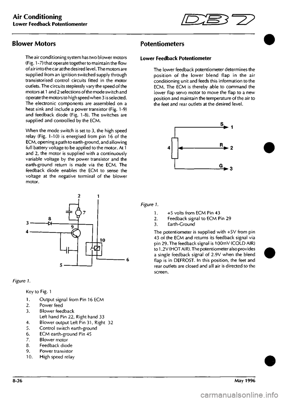
The air conditioning system has two blower motors
(Fig.
1
-7) that operate together to maintain the flow
of air into the car at the desired
level.
The motors are
supplied from an ignition switched supply through
transistorised control circuits fitted in the motor
outlets. The circuits steplessly vary the speed of the
motors at
1
and 2 selections of the mode switch and
operate the motors to high speed when 3
is
selected.
The electronic components are assembled on a
heat sink and include a power transistor (Fig.
1
-9)
and feedback diode (Fig. 1-8). The switches are
supplied and controlled by the ECM.
When the mode switch is set to 3, the high speed
relay (Fig. 1-10) is energised from pin 16 of the
ECM,
opening
a
path to earth-ground, and allowing
full battery voltage to be applied to the motor. At 1
and 2, the motor is supplied with a continuously
variable voltage by the power transistor and the
earth-ground return is made via the ECM. The
feedback diode enables the ECM to sense the
voltage at the negative terminal of the blower
motor.
Lower Feedback Potentiometer
The lower feedback potentiometer determines the
position of the lower blend flap in the air
conditioning unit and feeds this information to the
ECM.
The ECM is thereby able to command the
lower flap servo motor to move the flap to a new
position and maintain the temperature of the air to
the feet and rear outlets at the desired level.
V 1
• 2
V3
Figure 1.
Key to Fig. 1
1.
Output signal from Pin 16 ECM
2.
Power feed
3. Blower feedback
Left hand Pin 22, Right hand 33
4.
Blower output Left Pin 31, Right 32
5. Control switch earth-ground
6. ECM earth-ground Pin 45
7. Blower motor
8. Feedback diode
9. Power transistor
10.
High speed relay
Figure 1.
1.
2.
3.
+5 volts from ECM Pin 43
Feedback signal to ECM Pin 29
Earth-Ground
The potentiometer is supplied with +5V from pin
43 of the ECM and returns its feedback signal via
pin 29. The feedback signal is 10OmV (COLD AIR)
to 1.2 V (HOT A!
R).
The potentiometer also provides
a single feedback signal of 2.9V when the blend
flap is in DEFROST. In this position, the feet and
rear outlets are closed and all air is directed to the
screen.
8-26 May 1996
Page 307 of 421
Air Conditioning
System Fault Diagnosis ^=2?
System Fault Diagnosis
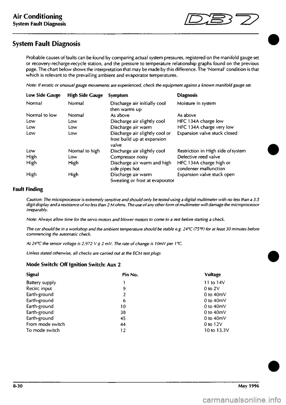
Probable causes of faults can be found by comparing actual system pressures, registered on the manifold gauge set
or recovery-recharge-recycie station, and the pressure to temperature relationship graphs found on the previous
page.
The chart below shows the interpretation that may be made by this difference. The 'Normal' condition is that
which is relevant to the prevailing ambient and evaporator temperatures.
Note: If erratic or
unusual gauge movements
are experienced, check the equipment
against a
known manifold
gauge
set.
Low Side
Normal
Gauge
Normal to low
Low
Low
Low
Low
High
High
High Side Gauge
Normal
Normal
Low
Low
Low
Normal to high
Low
High
High
Fault Finding
High
Symptom
Discharge air initially cool
then warms up
As above
Discharge air slightly cool
Discharge air warm
Discharge air slightly cool or
frost build up at expansion
valve
Discharge air slightly cool
Compressor noisy
Discharge air warm and high
side pipes hot
Discharge air warm
Sweating or frost at evaporator
Diagnosis
Moisture in system
As above
HFC 134A charge low
HFC 134A charge very low
Expansion valve stuck closed
Restriction in High side of system
Defective reed valve
HFC 134A charge high or
condenser malfunction
Expansion valve stuck open
Caution:
The microprocessor is extremely sensitive
and should only
be tested
using
a
digital multimeter with no
less
than a 3.5
digit display and a
resistance
of no
less than
2 M
ohms.
The use
of any other form of multimeter will
damage the microprocessor
irreparably.
Note: Always allow time for the
servo
motors and blower motors to come to a
rest
before starting a
check.
The car should be in a workshop and the ambient
temperature
should
be
stable
e.g.
24''C
(75°F)
for at
least
30 minutes before
commencing the automatic
check.
At 24°C the
sensor
voltage is
2.972
V
± 2 mV.
The
rate of
change
is lOmVper
1
°C.
Unless
stated
otherwise,
all
checks
are carried out at the ECM
test plugs
Mode Switch: Off Ignition Switch: Aux 2
Signal Pin No.
Battery supply 1
Recirc input 9
Earth-ground 2
Earth-ground 6
Earth-ground 10
Earth-ground 38
Earth-ground 45
From mode switch 44
To mode switch 12
Voltage
n to 14v
0to2V
0 to 40mV
0 to 40mV
0 to 40mV
0 to 40mV
0 to 40mV
0 to 12V
10 to 13.3V
8-30 May 1996
Page 344 of 421
^=2?
Air Conditioning
Portable Diagnostic Unit - Signal Definitions
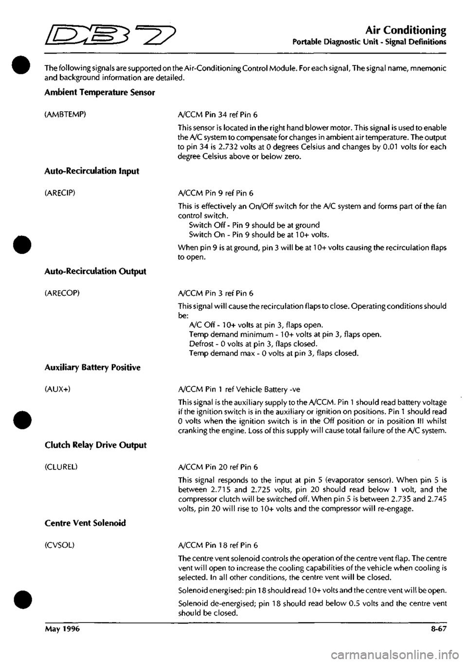
ThefollowingsignalsaresupportedontheAir-ConditioningControlModule. For each signal. The signal name, mnemonic
and background information are detailed.
Ambient Temperature Sensor
(AMBTEMP)
Auto-Recircuiation Input
(ARECIP)
Auto-Recirculation Output
(ARECOP)
Auxiliary Battery Positive
(AUX+)
Clutch Relay Drive Output
(CLUREL)
A/CCM Pin 34 ref Pin 6
This sensor is located in the right hand blower motor. This signal is used to enable
the A/C system to compensate for changes in ambient air temperature. The output
to pin 34 is 2.732 volts at 0 degrees Celsius and changes by 0.01 volts for each
degree Celsius above or below zero.
A/CCM Pin 9 ref Pin 6
This is effectively an On/Off switch for the A/C system and forms part of the fan
control switch.
Switch Off - Pin 9 should be at ground
Switch On - Pin 9 should be at 10+ volts.
When pin 9 is at ground, pin 3 will be at 10+ volts causing the recirculation flaps
to open.
A/CCM Pin 3 ref Pin 6
This signal will cause the recirculation flaps to close. Operating conditions should
be:
A/C Off - 10+ volts at pin 3, flaps open.
Temp demand minimum - 10+ volts at pin 3, flaps open.
Defrost - 0 volts at pin 3, flaps closed.
Temp demand max - 0 volts at pin 3, flaps closed.
A/CCM Pin 1 ref Vehicle Battery -ve
This signal istheauxiliary supply to the A/CCM. Pin
1
should read battery voltage
if the ignition switch is in the auxiliary or ignition on positions. Pin
1
should read
0 volts when the ignition switch is in the Off position or in position III whilst
cranking the engine. Loss of this supply will cause total failureof the A/C system.
A/CCM Pin 20 ref Pin 6
This signal responds to the input at pin 5 (evaporator sensor). When pin 5 is
between 2.715 and 2.725 volts, pin 20 should read below 1 volt, and the
compressor clutch will be switched off. When pin 5 is between 2.735 and 2.745
volts,
pin 20 will rise to 10+ volts and the compressor will re-engage.
Centre Vent Solenoid
(CVSOL) A/CCM Pin 18 ref Pin 6
The centre vent solenoid controls the operation of the centre vent flap. The centre
vent will open to increase the cooling capabilities of the vehicle when cooling is
selected.
In all other conditions, the centre vent will be closed.
Solenoid energised: pin 18 should read 10+volts and the centre vent will be open.
Solenoid de-energised; pin 18 should read below 0.5 volts and the centre vent
should be closed.
May 1996 8-67
Page 349 of 421
Air Conditioning
Portable Diagnostic Unit Signal Definitions ~3^^?
Measurement Probe
(MPROBE)
Switched Power Input
(POWIN+)
Power Output
(POWOP+)
Right Blower Feedback Voltage
(RBLOFB)
Right Blower Output Voltage
(RBLOWOP)
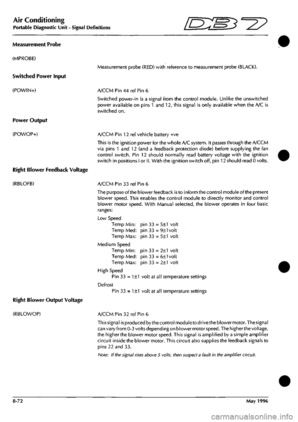
Measurement probe (RED) with reference to measurement probe (BLACK).
A/CCM Pin 44 ref Pin 6
Switched power-in is a signal from the control module. Unlike the unswitched
power available on pins 1 and 12, this signal is only available when the A/C is
switched on.
A/CCM Pin 12 ref vehicle battery +ve
This is the ignition power for the whole A/C system. It passes through the A/CCM
via pins 1 and 12 (and a feedback protection diode) before supplying the fan
control switch. Pin 12 should normally read battery voltage with the ignition
switch in positions I or
II.
With the ignition switch off, pin 12 should read 0 volts.
A/CCM Pin 33 ref Pin 6
The purpose of the blower feedback is to inform the control module of the present
blower speed. This enables the control module to directly monitor and control
blower motor speed. With Manual selected, the blower operates in four basic
ranges:
Low Speed
Temp Min:
Temp Med:
Temp Max:
Medium Speed
Temp Min:
Temp Med:
Temp Max:
High Speed
Pin 33 = 1±1 volt at all temperature settings
Defrost
Pin 33 = 1±1 volt at all temperature settings
pin 33 = 5±1 volt
pin 33 = 9±1volt
pin 33 = 5±1 volt
pin 33 = 2±1 volt
pin 33 = 6±1volt
pin 33 = 2±1 volt
A/CCM Pin 32 ref Pin 6
This signal is produced by the control module to drive the blower motor. The signal
can vary from 0-3 volts depending on blower motor
speed.
The higher the voltage,
the higher the blower motor speed. This signal is amplified by a simple amplifier
circuit inside the blower motor. This circuit also supplies the feedback signals to
pins 22 and 33.
Note: If
the
signal
rises
above 5 volts, then
suspect a
fault in the amplifier circuit.
8-72 May 1996
Page 379 of 421
The Aston Martin Lagonda Diagnostic System
Users Guide o: "3^^?
PDU Functions
The PDU main menu provides access into the following functions:
Diagnostics
Training
Digital Multimeter
User Self Test
Diagnostics
On selecting'Diagnostics'from the main
menu,
the user will be prompted to enter the features and market specification
of the vehicle to be tested. Use of the diagnostics in each of the above areas is described later in this guide.
Diagnostics Menu - 95 Model Year
Engine
Anti-Lock Braking System
Vlenu - 97 Model Year
Engine Diagnostics
OBD II Scan Tool
Airbag
Seat Belt Pretensioner
•
•
•
•
Transmission
Engine Datalogger
Climate Control
PATS System
Climate Control
Transmission
Anti-Lock Braking System
Security
Digital Multimeter
The Digital Multimeter function provides the capabilityto measure voltage, current, resistance, frequency, pulse width,
pulse period, and duty cycle. These measurements are usually made using the PDU measurement probes. Measurements
may also be made using the module pin selection function on the Teves Mk
II
braking system and on the Air Conditioning
system.
Training
An on-screen programme is provided to train new users in the use of screen icons and in the use of the digital multi
meter and datalogger functions.
User Self Test
In order to prove that the equpment is functioning correctly, a complete user self test is incorporated. The user is directed
to test the PDU and then to progressively connect each part of the PDU system which will be tested by the software.
Any fault identified during the test is notified to the user. If no faults are identified, the user is advised on the correct
functioning of the system.
PDU Power
Power for the PDU is supplied via an internal rechargeable battery pack which can keep the PDU operational for
approximately one hour when disconnected from the base station and the vehicle. In order to preserve PDU battery
charge, power to the screen backlight is automatically cut after five minutes of inactivity. The power ON indicator
remains lit, indicating that the PDU is in 'stand-by' mode. One touch of the screen will restore backlight power.
When connected to the base station, power is supplied to the PDU from the Electronic Module to recharge the PDU
battery pack as necessary.
On 95 MY vehicles, the Vehicle Battery Adaptor (VBA) is used to maintain PDU power.
On 97 MY vehicles, when connected via the MPA to either diagnostic socket on the vehicle, power is supplied via pin
4 (chassis ground) and pin 16 (battery power) to maintain PDU power at all times even when the vehicle ignition is
switched off.
On all model years, when connected to the air conditioning system using the VIA, the vehicle battery adaptor (VBA)
must also be used to maintain PDU power.
9-28 September 1996