width ASTON MARTIN DB7 1997 Workshop Manual
[x] Cancel search | Manufacturer: ASTON MARTIN, Model Year: 1997, Model line: DB7, Model: ASTON MARTIN DB7 1997Pages: 421, PDF Size: 9.31 MB
Page 379 of 421

The Aston Martin Lagonda Diagnostic System
Users Guide o: "3^^?
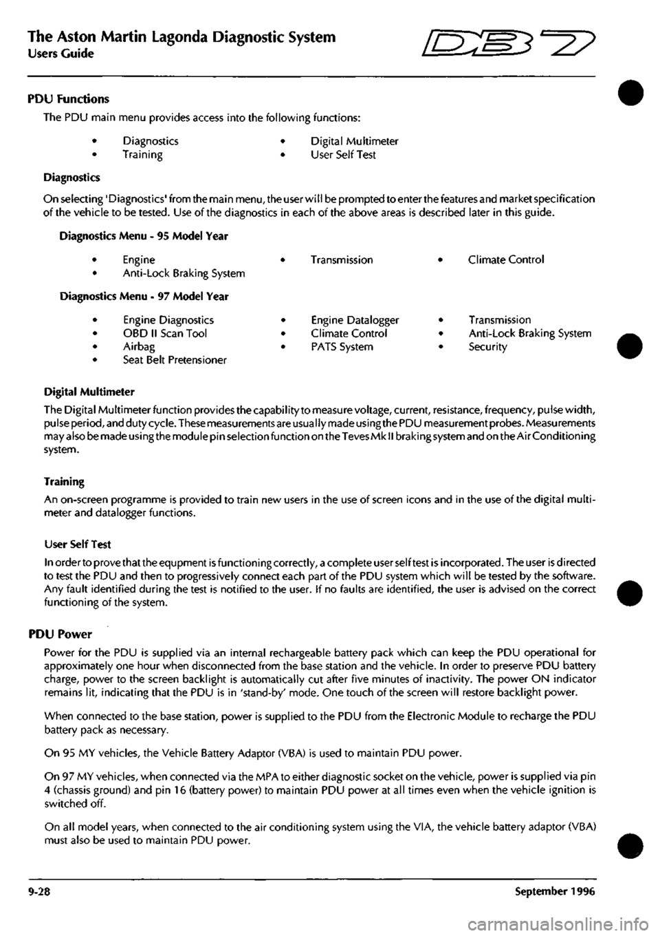
PDU Functions
The PDU main menu provides access into the following functions:
Diagnostics
Training
Digital Multimeter
User Self Test
Diagnostics
On selecting'Diagnostics'from the main
menu,
the user will be prompted to enter the features and market specification
of the vehicle to be tested. Use of the diagnostics in each of the above areas is described later in this guide.
Diagnostics Menu - 95 Model Year
Engine
Anti-Lock Braking System
Vlenu - 97 Model Year
Engine Diagnostics
OBD II Scan Tool
Airbag
Seat Belt Pretensioner
•
•
•
•
Transmission
Engine Datalogger
Climate Control
PATS System
Climate Control
Transmission
Anti-Lock Braking System
Security
Digital Multimeter
The Digital Multimeter function provides the capabilityto measure voltage, current, resistance, frequency, pulse width,
pulse period, and duty cycle. These measurements are usually made using the PDU measurement probes. Measurements
may also be made using the module pin selection function on the Teves Mk
II
braking system and on the Air Conditioning
system.
Training
An on-screen programme is provided to train new users in the use of screen icons and in the use of the digital multi
meter and datalogger functions.
User Self Test
In order to prove that the equpment is functioning correctly, a complete user self test is incorporated. The user is directed
to test the PDU and then to progressively connect each part of the PDU system which will be tested by the software.
Any fault identified during the test is notified to the user. If no faults are identified, the user is advised on the correct
functioning of the system.
PDU Power
Power for the PDU is supplied via an internal rechargeable battery pack which can keep the PDU operational for
approximately one hour when disconnected from the base station and the vehicle. In order to preserve PDU battery
charge, power to the screen backlight is automatically cut after five minutes of inactivity. The power ON indicator
remains lit, indicating that the PDU is in 'stand-by' mode. One touch of the screen will restore backlight power.
When connected to the base station, power is supplied to the PDU from the Electronic Module to recharge the PDU
battery pack as necessary.
On 95 MY vehicles, the Vehicle Battery Adaptor (VBA) is used to maintain PDU power.
On 97 MY vehicles, when connected via the MPA to either diagnostic socket on the vehicle, power is supplied via pin
4 (chassis ground) and pin 16 (battery power) to maintain PDU power at all times even when the vehicle ignition is
switched off.
On all model years, when connected to the air conditioning system using the VIA, the vehicle battery adaptor (VBA)
must also be used to maintain PDU power.
9-28 September 1996
Page 388 of 421

^
The Aston Martin Lagonda Diagnostic System
Users Guide
Signal Description
lACDTCY Idle Air Control Duty Cycle (% open)
lAT Intake Air Temperature - °C or raw input counts
lAT STAT Air Temperature - Temperature sensor failure
lAT-V Intake Air Temperature - Volts or raw counts
IGN Desired Ignition Timing - ° BTDC
INDS Input from manual lever position sensor (counts)
IPWA Injector Pulse Width in mS- Bank A (Cylinders
1
-3)
IPWB Injector Pulse Width in mS- Bank B (Cylinders 4-6)
LAMSE1 Current Short Term Fuel Trim 1, adjustment from stoich - (% of range)
LAMSE2 Current Short Term Fuel Trim 2, adjustment from stoich - (% of range)
LFC Low Speed Fan Status
LOOP Fuel Control -1 = Open Loop, 0 = Closed Loop
MAF MAX Maximum Mass Air Flow signal during normal running
MAF Raw MAF sensor output (A/D counts)
MAF STAT Mass Air Flow Meter - MAF sensor failure
MIL Mali Indicator Lamp Status -1 = Lamp On
Mis HI Cumulative misfires detected by misfire test (Hi bit).
Mis LO Cumulative misfires detected by misfire test (Lo bit).
Mis nc HI Cumulative misfires detected by a misfire test (Hi bit).
Mis nc LO Cumulative misfires detected by a misfire test.
Misi HI Cumulative misfires detected by cylinder
1
misfire test (Hi bit).
Misi LO Cumulative misfires detected by cylinder
1
misfire test (Lo bit).
Mis2 HI Cumulative misfires detected by cylinder 2 misfire test (Hi bit).
Mis2 LO Cumulative misfires detected by cylinder 2 misfire test (Lo bit).
Mis3 HI Cumulative misfires detected by cylinder 3 misfire test (Hi bit).
Mis3 LO Cumulative misfires detected by cylinder 3 misfire test (Lo bit).
Mis4 HI Cumulative misfires detected by cylinder 4 misfire test (Hi bit).
Mis4 LO Cumulative misfires detected by cylinder 4 misfire test (Lo bit).
Mis5 HI Cumulative misfires detected by cylinder 5 misfire test (Hi bit).
Mis5 LO Cumulative misfires detected by cylinder 5 misfire test (Lo bit).
Mis6 HI Cumulative misfires detected by cylinder 6 misfire test (Hi bit).
Mis6 LO Cumulative misfires detected by cylinder 6 misfire test (Lo bit).
MISF Misfire Monitor - 1 = Currently misfiring
ODCODES Total number of on-demand codes currently stored.
PGM CVS DC Purge Management Duty Cycle (% on)
PIP Profile ignition Pick-Up - PIP input level
PNP Park Neutral Position Switch
R-BIAS1 Rear bias trim (Bank 1, cylinders
1
-3)
R-BIAS2 Rear bias trim (Bank 2, cylinders 4-6)
RATCH Lowest TP reading during driving
TP MAX Maximum Throttle Potentiometer signal during normal running
TP STAT Throttle Position Sensor - TP sensor failure
TP Throttle Potentiometer - Volts or counts
TPR-V Raw counts from sensor
TQ-NET Net torque into the torque convertor
TRIP OBDII Drive Cycle Complete (except cat monitor) - 1 = Trip completed
TRIPCNT Number of Completed OBDII Trips
VS MAX Maximum Vehicle Speed signal during normal running
VS STAT Vehicle Speed Sensor mode flag
VS Vehicle Speed - MPH
WAC Wide Open Throttle A/C Cut-Off -1 = High (WOT Relay)
September 1996 9-37
Page 393 of 421

The Aston Martin Lagonda Diagnostic System
Users Guide ^7
TCCS Torque Convertor Clutch Solenoid
The torque converter clutch solenoid is mounted on the
valve body. The signal is Pulse Width Modulated at 32Hz
to provide closed loop control of the pressure across the
converter clutch plates. 1 bit = 0.39% Range 0 to 100%
TP Throttle Position
This is provided by the EECV Engine Management System
as a Pulse Width Modulated signal derived from the
throttle position signal read by that module from the
throttle position sensor.
TCS Torque Convertor Slip
Torque converter slip is defined
as
the difference between
the Input/turbine (ni) speed and the Engine speed (Ne):
Slip = Ne-Ni. The PWM duty cycle may increase from 0
to 100% when TCC is fully applied. In practice a 100%
duty cycle will be achieved only if
a
large slip is detected.
Normal ly only a 50 to 95% duty cycle will be required for
full application of the TCC. Slip is expressed in rpm. 1 Bit
- 1/8 rpm. Range -4096 to +4096 rpm.
TCSW Transmission Control Switch
A three position switch allows the driver to select Sport,
Normal or 1st Gear Inhibit mode. When 'Sport' is selected
gearshifts take place at higher engine revs. When '1st
Gear Inhibit' is selected, the transmission only operates in
the higher forward ratios to prevent wheel slip in icy
conditions.
TISSA Turbine Input Shaft Speed
Turbine speed is the speed of the input shaft of the
transmission measured by the input speed sensor mounted
on the transmission. An alternating waveform is induced
in the sensor by 31 serrations on the forward clutch
housing as it rotates. The waveform frequency and
amplitude is low at low speeds and high at high speeds.
The TCM changes this signal into a digital signal. 1 bit =
1/8 RPM. Range: 0 - 8192 RPM.
TOS+ Transmission Output Speed
The output speed sensor is mounted on the transmission
case and measures the speed of the output shaft. As the
shaft rotates an alternating waveform is induced in the
sensor which varies in frequency and voltage. The wave
form is converted into
a
digital signal by the TCM and used
to control TCC, line pressure, shift timing and torque
management. 1 bit = 1/8 RPM. Range 0-8192 RPM
TRX Transmission Control Switch X
TRY Transmission Control Switch Y
TRZ Transmission Control Switch Z
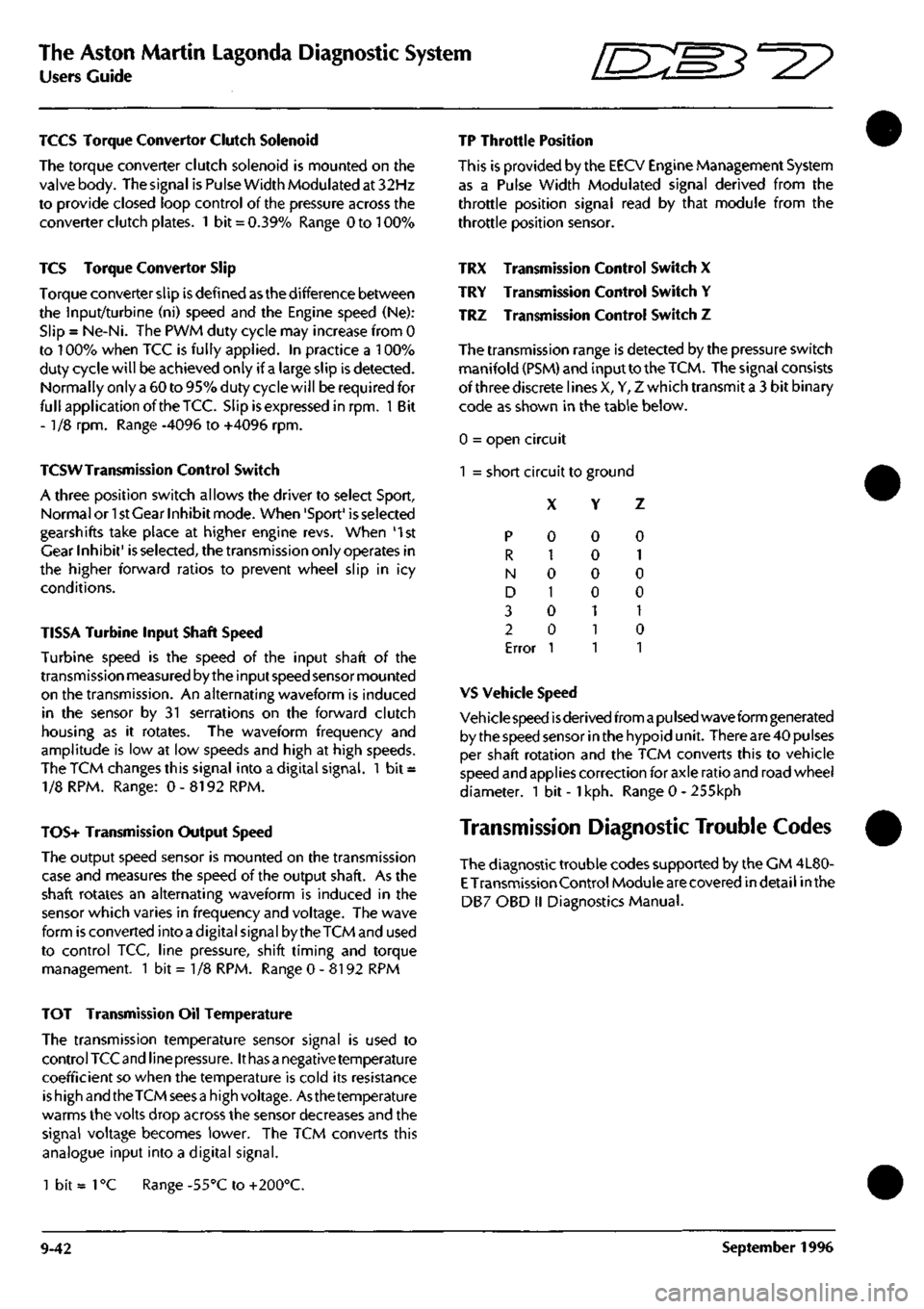
The transmission range is detected by the pressure switch
manifold (PSM) and input to the
TCM.
The signal consists
of three discrete lines X, Y, Z which transmit a 3 bit binary
code as shown in the table below.
0 = open circuit
1 = short circuit to ground
X Y Z
p
R
N
D
3
2
Error
0
1
0
1
0
0
1
0
0
0
0
1
1
1
0
1
0
0
1
0
1
VS Vehicle Speed
Veh icie speed
is
derived from
a pu Ised
wave form generated
by the speed sensor in the hypoid unit. There are 40 pulses
per shaft rotation and the TCM converts this to vehicle
speed and applies correction for axle ratio and road wheel
diameter. 1 bit -
1
kph. Range 0 - 255kph
Transmission Diagnostic Trouble Codes
The diagnostic trouble codes supported by the CM 4L80-
E
Transmission Control Module are covered indetail inthe
DB7 OBD II Diagnostics Manual.
TOT Transmission Oil Temperature
The transmission temperature sensor signal is used to
control TCC and line
pressure.
It
has a
negative temperature
coefficient so when the temperature is cold its resistance
is high and the TCM sees
a
high voltage. Asthe temperature
warms the volts drop across the sensor decreases and the
signal voltage becomes lower. The TCM converts this
analogue input into a digital signal.
1 bit =
1
°C Range -55°C to +200°C.
9-42 September 1996
Page 401 of 421

The Aston Martin Lagonda Diagnostic System
Users Guide ^=2?
Printer Use Digital Multimeter
Print Trace
The Trace Buffer is used to record technician use of the
PDU.As the diagnostics are executed, the following
information is written to trace:
Screen Title
Menu options selected
Operator questions selected
Operator actions
Control module information
Test limits and results
P codes detected by the DTC monitor
Snapshot data from the datalogger
OBD II freeze frame data
Set up the printer and load with paper. Select Print
Trace and confirm the selection. All recorded
information in the above list will be printed.
Printtrace is supported in English, French, German and
Italian.
Print Screen
The Print Screen function dumps a bitmap image of the
current screen display to the printer. This function is
particularly useful for recordingdata such as waveforms
captured by the datalogger application.
The print screen function is supported in English,
French,
German, Italian and Japanese.
Introduction
The Digital Multi-Meterprovidesthecapability to measure
voltage, current, resistance, frequency, pulse width, pulse
period and duty cycle using measurement probes or
vehicle interface adaptor channels.
WARNING: DMM measurements must not be taken
while the PDU
is
connected to the
base
station. The PDU
measurement system
becomes
referenced to earth when
connected to the base station. Serious measurement
errors may be present
because
of any voltage difference
between vehicle ground and base station earth. Operation
of the PDU in this mode has both functional and safety
implications and therefore must be
avoided.
A digital multimeter (DMM) is resident within the PDU
software toolbox.
The DMM application can be accessed from the main
menu.
On selection of "Digital Multimeter" from the main
menu,
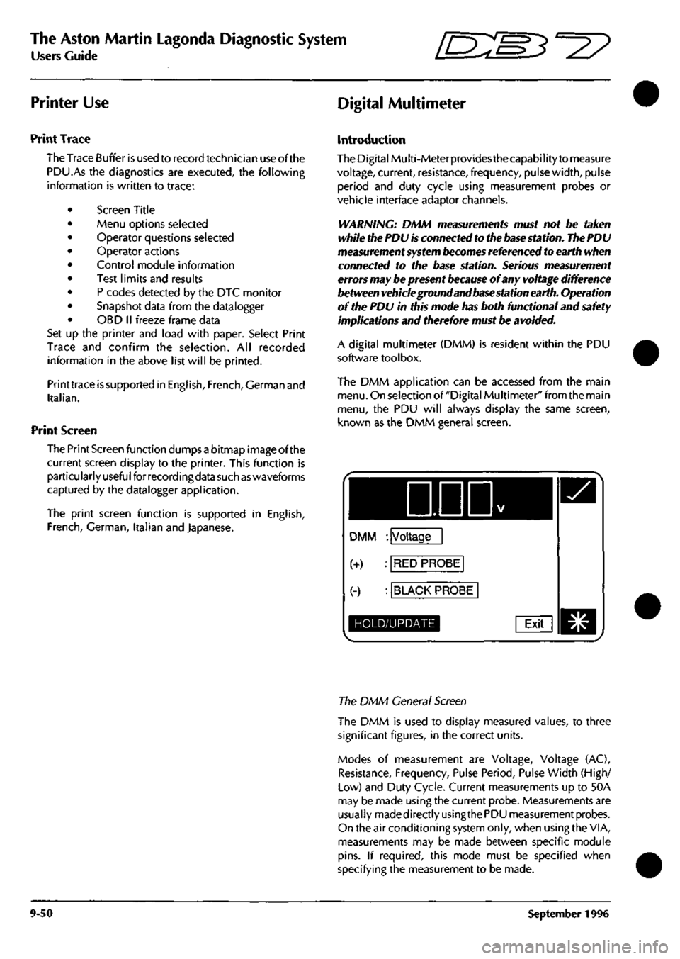
the PDU will always display the same screen,
known as the DMM general screen.
DDD
DMM : Voltage
(+) : RED PROBE
(-) : BLACK PROBE
HOLD/UPDATE Exit
The DMM General Screen
The DMM is used to display measured values, to three
significant figures, in the correct units.
Modes of measurement are Voltage, Voltage (AC),
Resistance, Frequency, Pulse Period, Pulse Width (High/
Low) and Duty Cycle. Current measurements up to 50A
may be made using the current probe. Measurements are
usually madedirectlyusingthe PDU measurement probes.
On the air conditioning system only, when using the VIA,
measurements may be made between specific module
pins.
If required, this mode must be specified when
specifying the measurement to be made.
9-50 September 1996
Page 402 of 421

^^?
The Aston Martin Lagonda Diagnostic System
Users Guide
Operation
On selection of DMM the general screen, as shown in Fig.
1,
will be displayed.
Voltage is the default selection for measurement, with red
and black probes selected
as
sources.
To choose alternatives
to these options, press the relevant description for change
followed by the 'tick' icon in the top, right-hand, corner.
If the measurement mode (Voltage) is selected for change,
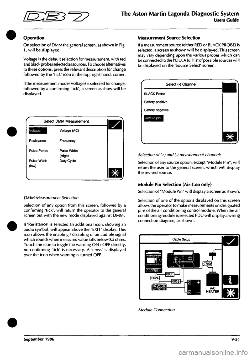
followed by a confirming 'tick', a screen as show will be
displayed.
Select DMM Measurement
^Q^||[
Resistance
Pulse Period
Pulse Width
(low)
Voltage (AC)
Frequency
Pulse Width
(High)
Duty Cycle
DMM Measurement Selection
Selection of any option from this screen, followed by a
confirming 'tick', will return the operator to the general
screen but with the new mode displayed against DMM.
If 'Resistance' is selected an additional
icon,
showing an
audio symbol, will appear above the "EXIT" display. This
icon allows the enabling / disabling of an audible signal
which sounds when measured valuefal
Is
below 0.5 ohms.
Touch the icon to toggle the warning ON / OFF directly,
no confirming 'tick' is necessary. A 'cross' is displayed
over the icon when warning is turned OFF.
Measurement Source Selection
If
a
measurement source (either RED or BLACK PROBE) is
selected,
a screen as shown will be displayed. This screen
may vary depending upon the various probes which can
be connected to the PDU.Afull list of possiblesources will
be displayed on the 'Source Select' screen.
Select (-) Channel
BLACK Probe
Battery positive
Battery negative
Module pin
Selection of (+) and (-) measurement channels
Selection of any source option, except "Module Pin", will
return the user to the general screen, which will display
the revised source.
Module Pin Selection (Air-Con only)
Selection of "Module Pin" will display a screen as shown.
Selection of one of the options displayed on this screen
allows the operator to make measurements on designated
pins of the air conditioning control module. When the air
conditioning module is selected PDU will display a wiring
connection diagram, as shown.
Cable Setup
Module Connection
September 1996 9-51