lock ASTON MARTIN DB7 1997 Repair Manual
[x] Cancel search | Manufacturer: ASTON MARTIN, Model Year: 1997, Model line: DB7, Model: ASTON MARTIN DB7 1997Pages: 421, PDF Size: 9.31 MB
Page 334 of 421
^?
Air Conditioning Repair Procedures
upper/Lower Servo Feedback Potentiometer Renew
8.2.03.1
Upper Servo Feedback
Potentiometer Renewal
8.2.04.1
Lower Servo Feedback
Potentiometer Renew
1.
Disconnect the battery earth
lead.
2.
(On left hand cars) Remove the instrument paci<
and surround
trim.
2.
(On right hand cars) Remove the glove box
assembly.
3.
Remove the
securing screws
and
the potentiometer
assembly. Disconnect the electrical connector.
4.
Fitting a new potentiometer is the reverse of the
removal procedure.
1.
Disconnect the battery earth
lead.
2.
Un-clip and remove the left hand underscuttle
casing.
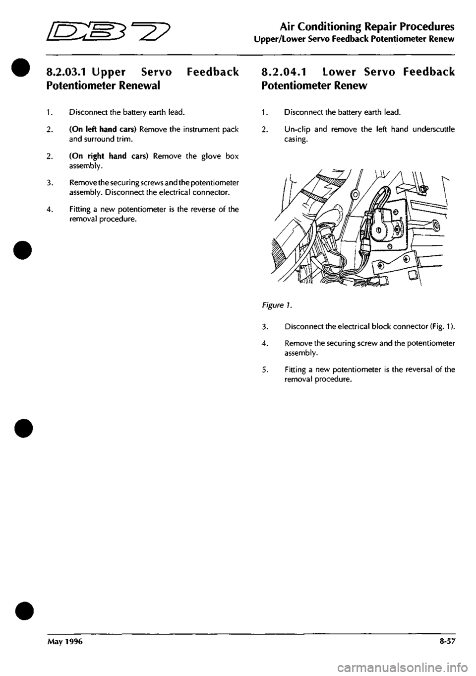
Figure 1.
3. Disconnect the electrical block connector
(Fig.
1).
4.
Remove the securing screw and the potentiometer
assembly.
5. Fitting a new potentiometer is the reversal of the
removal procedure.
May 1996 8-57
Page 335 of 421
Air Conditioning Repair Procedures
Upper/Lower Flap Motor Renew [EB^^^?
8.2.05.1 Upper Flap Motor Assembly
Renew
8.2.06.1 Lower Flap Motor Assembly
Renew
1.
Disconnect the battery earth
lead.
2.
Remove the electronic control module.
3. Disconnect the motor block connector.
4.
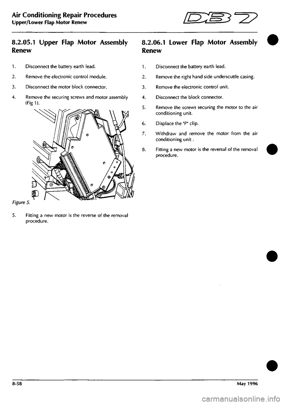
Remove the securing screws and motor assembly
(Figl).
Figure
5.
5. Fitting a new motor is the reverse of the removal
procedure.
1.
Disconnect the battery earth
lead.
2.
Remove the right hand side underscuttle casing.
3. Remove the electronic control unit.
4.
Disconnect the block connector.
5. Remove the screws securing the motor to the air
conditioning unit.
6. Displace the'P'clip.
7. Withdraw and remove the motor from the air
conditioning unit.
8. Fitting a new motor is the reversal of the removal
procedure.
8-58 May 1996
Page 336 of 421
'nzm^=2?
Air Conditioning Repair Procedures
Blower Motor Renewal
8.2.07.1 Ambient Temperature Sensor
Renew
?\gure
1.
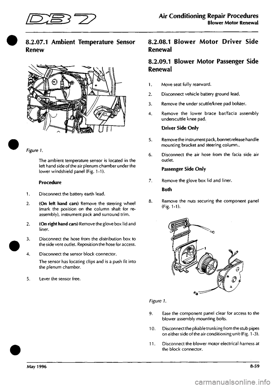
The ambient temperature sensor is located in the
left hand side of the air plenum chamber under the
lower windshield panel (Fig. 1-1).
Procedure
1.
Disconnect the battery earth
lead.
2.
(On left hand cars) Remove the steering wheel
(mark the position on the column shaft for re
assembly), instrument pack and surround
trim.
2.
(On right hand cars) Removethegloveboxlidand
liner.
3. Disconnect the hose from the distribution box to
the side vent outlet. Reposition the hose for access.
4.
Disconnect the sensor block connector.
The sensor has locating clips and is a push fit into
the plenum chamber.
5. Lever the sensor free.
8.2.08.1 Blower Motor Driver Side
Renewal
8.2.09.1 Blower Motor Passenger Side
Renewal
1.
Move seat
fu 1
ly rearward.
2.
Disconnect vehicle battery ground
lead.
3. Remove the under scuttle/knee pad bolster.
4.
Remove the lower brace bar/facia assembly
underscuttle knee pad.
Driver Side Only
5. Removetheinstrumentpack, bonnetreieasehandle
mounting bracket and steering column..
6. Disconnect the air hose from the facia side air
outlet.
Passenger Side Only
7. Remove the glove box lid and liner.
Both
8. Remove the nuts securing the component panel
(Fig.
1-1).
Figure 1.
9. Ease the component panel clear for access to the
blower assembly mounting bolts.
10.
Disconnect the pliable trunking from the stub pipes
on either side of the air conditioning unit
(Fig.
1
-3).
11.
Disconnect the blower motor electrical harness at
the block connector.
May 1996 8-59
Page 340 of 421
^>
Air Conditioning Repair Procedures
Electronic Control Module/Vacuum Solenoid Renewal
8.2.14.1 Electronic Control Module
Renew
8.3.01.1 Vacuum System Solenoid
Renewal
1.
Disconnect the battery earth
lead.
2.
Remove the right hand underscuttle casing.
3. (On left hand cars) Removethe glove box assembly.
3. (On right hand cars) Remove the instrument pack
and surround
trim.
4.
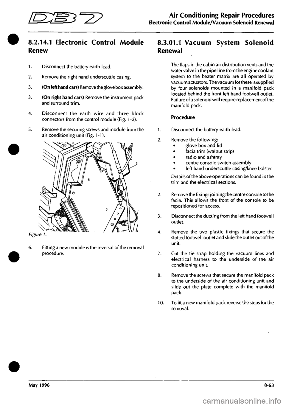
Disconnect the earth wire and three block
connectors from the control module (Fig.
1
-2).
5. Remove the securing screws and module from the
air conditioning unit (Fig. 1-1).
Fitting a new module
is
the reversal of the removal
procedure.
The flaps in the cabin air distribution vents and the
water valve in the pipe line from the engine coolant
system to the heater matrix are all operated by
vacuumactuators.The vacuumfor these issupplied
by four solenoids mounted in a manifold pack
located behind the front left hand footwell outlet.
Failureof a solenoid will require replacement of the
manifold pack.
Procedure
1.
Disconnect the battery earth
lead.
2.
Remove the following:
• glove box and lid
• facia trim (walnut strip)
• radio and ashtray
• centre console switch assembly
• left hand underscuttle casing/knee bolster
Detai
Is
ofthe above operations can be found in the
trim and the electrical sections.
2.
Remove thefixings joining the centre console to the
facia.
This allows the front of the console to be
repositioned for access.
3. Disconnect the ducting from the left hand footwell
outlet.
4.
Remove the two plastic fixings that secure the
slotted footwel
I
outlet and
si
ide the outlet out ofthe
unit.
7. Cut the tie strap holding the vacuum lines and
electrical harness to the underside of the air
conditioning unit.
8. Remove the screws that secure the manifold pack
to the underside of the air conditioning unit and
slide out the plate complete with the manifold
pack.
10.
To fit a new manifold pack reverse the steps for the
removal.
May 1996 8-63
Page 352 of 421
^?
The Aston Martin Lagonda Diagnostic System
Contents
Installation Instructions
Introduaion 9-2
The Aston Martin Diagnostic System 9-2
Diagnostic System Cables 9-5
Base Station Installation 9-8
Problem Solving 9-16
Service Centres 9-21
Service and Maintenance 9-22
Technical Specifications 9-24
Operating Instructions
The Aston Martin Lagonda Diagnostic System 9-27
Software 9-29
Cable Setup 9-31
Diagnostic Sockets - 97 MY 9-31
Establishing Communications 9-32
System Menu Selections 9-32
PDU Use 9-32
Engine Diagnostics - 97 MY 9-33
Transmission Diagnostics 9-40
Climate Control Diagnostics 9-43
Anti-Lock Brakes Diagnostics 9-43
Passive Anti-Theft (PATS) Diagnostics 9-44
Airbag System Diagnostics 9-45
Seat Belt Pretensioner Diagnostics 9-47
Print Facility 9-49
Digital Multimeter 9-50
Diagnostic Trouble Codes 9-53
Datalogger 9-55
Datalogger Example 9-63
Training 9-66
OBD II Scan Tool 9-66
System Self Test 9-69
The Asterisk (*) Menu 9-69
System Setup 9-70
May 1996 9-1
Page 354 of 421
'=^
The Aston Martin Lagonda Diagnostic System
Installation Instructions
12 10
19 22 21 20
VIA A / /^^>^ I B T
A-XA^I'A® QA
13
16
18 29
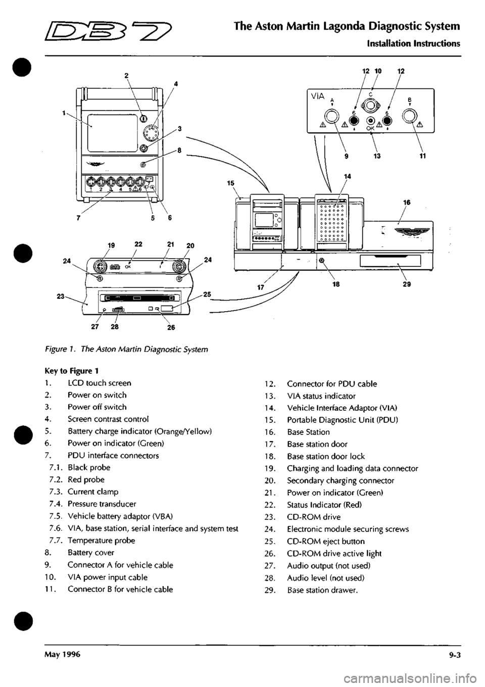
Figure 7. The Aston Martin Diagnostic System
Key to Figure 1
1.
2.
3.
4.
5.
6.
7.
7.1.
7.2.
7.3.
7.4.
7.5.
7.6.
7.7.
8.
9.
10.
11.
LCD touch screen
Power on switch
Power off switch
Screen contrast control
Battery charge indicator (Orange/Yellow)
Power on indicator (Green)
PDU interface connectors
Black probe
Red probe
Current clamp
Pressure transducer
Vehicle battery adaptor (VBA)
VIA, base station, serial interface and system test
Temperature probe
Battery cover
Connector A for vehicle cable
VIA power input cable
Connector B for vehicle cable
12.
13.
14.
15.
16.
17.
18.
19.
20.
21.
22.
23.
24.
25.
26.
27.
28.
29.
Connector for PDU cable
VIA status indicator
Vehicle Interface Adaptor (VIA)
Portable Diagnostic Unit (PDU)
Base Station
Base station door
Base station door lock
Charging and loading data connector
Secondary charging connector
Power on indicator (Green)
Status Indicator (Red)
CD-ROM drive
Electronic module securing screws
CD-ROM eject button
CD-ROM drive active light
Audio output (not used)
Audio level (not used)
Base station drawer.
May 1996 9-3
Page 357 of 421

The Aston Martin Lagonda Diagnostic System
Installation Instructions mm^^?
Diagnostic System Cables
311
^ri M
r 1
3130-0030-01 VIA-PDU Cable
^
ctfa
3130-0778-00-B Anti-Lock Brakes
3130-0064-01 Base Station-PDU Cable
3130-0475-00 Test Probes
VBA
3130-0024-01 Vehicle Battery Adapti
3130-0764-00 Road Test Ext Cable
9-6 May 1996
Page 360 of 421
^^?
The Aston Martin Lagonda Diagnostic System
I nstal lation I nstructions
Bench Mounting
The base station may also be mounted on a bench, which
must be in a safe position, stable and protected form
hazards and impacts. The base station must be mounted
at the back of the bench. 'Z' clips are provided for
permanent mounting. The bench surface must be kept free
from dust at all times.
CAUTION:
A gap under the base station must be
maintained free from obstructions to allow a flow of air
under the unit for cooling.
Electronic Module installation
WARNING: The base station electronic module must be
disconnected from the mains supply prior to installation/
removal from the base station assembly. DO NOT
reconnect to the mains supply until the module is safely
fitted into the base station. This unit must be earthed.
Note:
Users in North America are advised to replace the
ceramic mains fuse in the electronic module with theglass
fuse supplied.
Procedure
1.
Unlock the base station door
2.
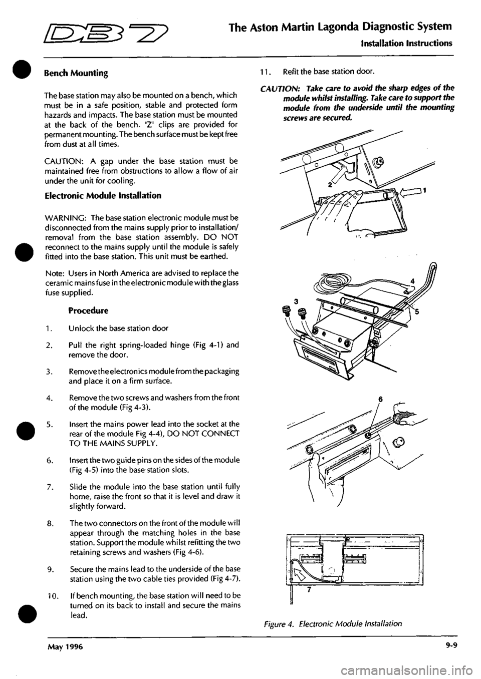
Pull the right spring-loaded hinge (Fig 4-1) and
remove the door.
3. Removetheelectronicsmodulefrom the packaging
and place it on a firm surface.
4.
Remove the two screws and washers from the front
of the module (Fig 4-3).
5. Insert the mains power lead into the socket at the
rear of the module Fig 4-4), DO NOT CONNECT
TO THE MAINS SUPPLY.
6. Insert the two guide pins on the sides of the module
(Fig 4-5) into the base station slots.
7. Slide the module into the base station until fully
home,
raise the front so that it is level and draw it
slightly forward.
8. The two connectors on the front of the module will
appear through the matching holes in the base
station.
Support the module whilst refitting the two
retaining screws and washers (Fig 4-6).
9. Secure the mains lead to the underside of the base
station using the two cable ties provided (Fig 4-7).
10.
If bench mounting, the base station will need to be
turned on its back to install and secure the mains
lead.
11.
Refit the base station door.
CAUTION: Take care to avoid the sharp edges of the
module whilst installing. Take care to support the
module from the underside until the mounting
screws are secured.
Figure 4. Electronic Module Installation
May 1996 9-9
Page 361 of 421
The Aston Martin Lagonda Diagnostic System
Installation Instructions
[ES^'^?
Powering-Up the Base Station
When first operating the System or when first using
a PDU fitted with substitute batteries, it will take up
to36 hourstoachievefull charge. Inthemeantime,
the PDU can be used whilst connected to the base
station or to the vehicle battery.
Vi/\RNmGS:
When using the system equipment, basic safety
precautions should always be followed, including:
Carefully read and follow all instructions.
Care should be taken as burns can occur from
touching hot parts.
Do not operate the appliance with a damaged
mains lead or if the appliance has been dropped or
damaged. Call your local GenRad Service Centre
immediately for a substitute
part.
Do not let the mains lead hang over the
edge
of the
table, bench or counter or come into contact with
hot manifolds or moving fan blades.
The Aston Martin Portable Diagnostic Unit
is
fitted with an
auto switching power supply suitable for voltage supplies
of 100 - 240 VAC 50 - 60 Hz. You need only check that
the power cord connector is of the correct type for your
power outlets.
1.
Connect the mains lead to the mains outlet.
2.
Check that the green indicator lamp above the base
station door is illuminated. If the green lamp does
not come on, see the problem solving section for
advice.
3. After a few seconds, during which the electronics
module completes its self-test, the red OK indicator
lamp should illuminate. If the red lamp does not
come on, see the problem solving section for
advice.
4.
Allow the base station electronics module to reach
working temperature. This will take approximately
BOminutes, after which time the base station will be
ready to accept the software on CD-ROM.
5. Slide the PDU into its carrying case and place the
associated cables and probes in the carrying case
compartments.
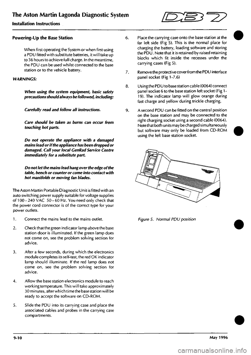
6. Place the carrying case onto the base station at the
far left side (Fig 5). This is the normal place for
charging the battery, loading software and storing
the PDU. Note that it is retained by raised retaining
blocks which fit inside the recesses under the
carrying cases (Fig 5).
7. Remove the protective coverfromthe PDU interface
panel socket (Fig
1
-7.6)
8. Usingthe PDU to base station cable (0064) connect
panel socket 6 to the base station left socket (Fig
1
-
19).
The indicator lamp will glow orange during
fast charge and yellow during trickle charging.
9. A second PDU can be fitted on the central position
on the base station and may be connected to the
right charging socket using a second cable (0064).
Note that both units may be charged simultaneously
but software may only be loaded from CD-ROM
using the left base station socket.
Figure 5. Normal PDU position
9-10 May 1996
Page 362 of 421
'D::B^^?
The Aston Martin Lagonda Diagnostic System
Installation Instructions
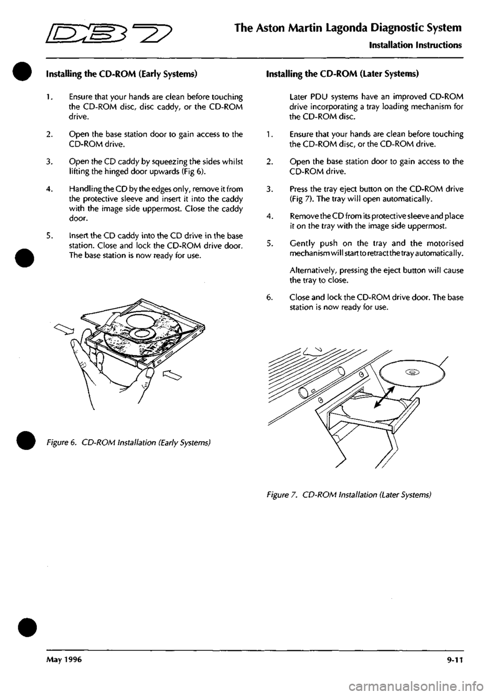
Installing the CD-ROM (Early Systems) Installing the CD-ROM (Later Systems)
2.
3.
5.
Ensure that your hands are clean before touching
the CD-ROM disc, disc caddy, or the CD-ROM
drive.
Open the base station door to gain access to the
CD-ROM drive.
Open the CD caddy by squeezing the sides whilst
lifting the hinged door upwards (Fig 6).
Handling the CD by the edges only, remove it from
the protective sleeve and insert it into the caddy
with the image side uppermost. Close the caddy
door.
Insert the CD caddy into the CD drive in the base
station.
Close and lock the CD-ROM drive door.
The base station is now ready for use.
Figure 6. CD-ROM Installation (Early Systems)
Later PDU systems have an improved CD-ROM
drive incorporating a tray loading mechanism for
the CD-ROM disc.
1.
Ensure that your hands are clean before touching
the CD-ROM disc, or the CD-ROM drive.
2.
Open the base station door to gain access to the
CD-ROM drive.
3. Press the tray eject button on the CD-ROM drive
(Fig 7). The tray will open automatically.
4.
Remove the CD from its protective sleeve and place
it on the tray with the image side uppermost.
5. Gently push on the tray and the motorised
mechanism will start to retractthe tray automatically.
Alternatively, pressing the eject button will cause
the tray to close.
6. Close and lock the CD-ROM drive door. The base
station is now ready for use.
Figure 7. CD-ROM Installation (Later Systems)
May 1996 9-11