ABS ASTON MARTIN DB7 1997 Workshop Manual
[x] Cancel search | Manufacturer: ASTON MARTIN, Model Year: 1997, Model line: DB7, Model: ASTON MARTIN DB7 1997Pages: 421, PDF Size: 9.31 MB
Page 27 of 421
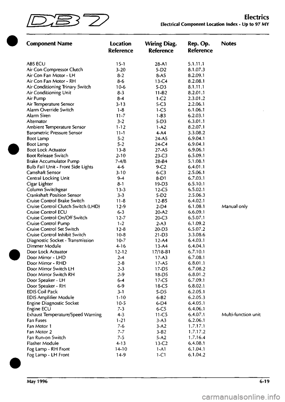
Electrics
Electrical Component Location Index - Up to 97 MY
Component Name
ABS ECU
Air Con Compressor Clutch
Air Con Fan Motor - LH
Air Con Fan Motor - RH
Air Conditioning Trinary Switch
Air Conditioning Unit
Air Pump
Air Temperature Sensor
Alarm Override Switch
Alarm Siren
Alternator
Ambient Temperature Sensor
Barometric Pressure Sensor
Boot Lamp
Boot Lamp
Boot Lock Actuator
Boot Release Switch
Brake Accumulator Pump
Bulb Fail Unit - Front Side Lights
Camshaft Sensor
Central Locking Unit
Cigar Lighter
Column Switchgear
Crankshaft Position Sensor
Cruise Control Brake Switch
Cruise Control Clutch Switch (LHD)
Cruise Control ECU
Cruise Control On/Off Switch
Cruise Control Pump
Cruise Control Set Switch
Cruise Control Inhibit Switch
Diagnostic Socket - Transmission
Dimmer Module
Door Lock Actuator
Door Mirror- LHD
Door Mirror- RHD
Door Mirror Switch LH
Door Mirror Switch RH
Door Speaker -LH
Door Speaker - RH
EDIS Coil Pack
EDIS Amplifier Module
Engine Diagnostic Socket
Engine ECU
Exhaust Temperature/Speed Warning
Fan Fuses
Fan Motor 1
Fan Motor 2
Fan Run-on Switch
Flasher Module
Fog Lamp - RH Front
Fog Lamp - LH Front
Location
Reference
15-1
3-20
8-2
8-6
10-6
8-3
8-4
3-13
1-8
11-7
3-2
1-12
11-1
5-2
5-2
13-8
2-10
7-4/8
4-6
3-10
9-4
8-1
13-3
3-3
11-8
12-9
6-3
12-7
1-2
12-8
10-8
10-7
4-16
12-12
2-4
2-8
2-3
2-9
6-4
6-9
3-1
1-10
10-5
7-3
4-3
1-21
7-6
7-7
7-5
4-13
14-10
14-9
Wiring Diag.
Reference
28-A1
5-D2
8-A5
13-C4
5-D3
11-82
1-C2
5-C3
1-C5
1-B3
5-D3
1-A2
4-A4
24-A5
24-C4
27-A5
l-i-C3
28-84
9-C2
6-C3
8-D1
19-D3
12-C5
5-D2
12-85
2-D4
20-A2
20-C3
2-A3
20-D3
21-D3
12-A4
13-A4
17/18-B1
17-A3
17-A5
17-D5
18-D5
17-C5
18-C5
5-D5
6-B2
6-D4
6-C5
11-C5
3-A3
3-A2
3-B2
5-A2
13-C2
1-A1
1-C1
Rep.
Op. Notes
Reference
5.1.11.1
8.1.07.3
8.2.09.1
8.2.08.1
8.1.11.1
8.2.01.1
2.3.01.2
2.2.06.1
6.1.06.1
6.2.03.1
6.3.01.1
8.2.07.1
3.3.08.2
6.9.04.1
6.9.04.1
6.9.06.1
6.5.09.1
5.1.08.1
6.4.01.1
2.5.06.1
6.7.03.1
6.5.10.1
6.5.02.1
2.5.06.3
6.4.02.1
6.1.08.1 Manual only
6.6.09.1
6.5.07.1
6.1.09.2
6.5.07.2
3.3.08.6
6.4.03.1
6.4.04.1
6.7.10.1
6.7.08.1
6.8.01.1
6.7.08.2
6.8.01.2
6.7.09.1
6.8.02.1
6.2.05.1
6.2.05.3
6.4.05.1
6.4.06.1
6.4.07.1 Multi-functio
6.2.06.1
1.7.17.1
1.7.17.2
1.7.16.4
6.4.08.1
6.1.04.1
6.1.04.2
May 1996 6-19
Page 29 of 421
[n:m3^y
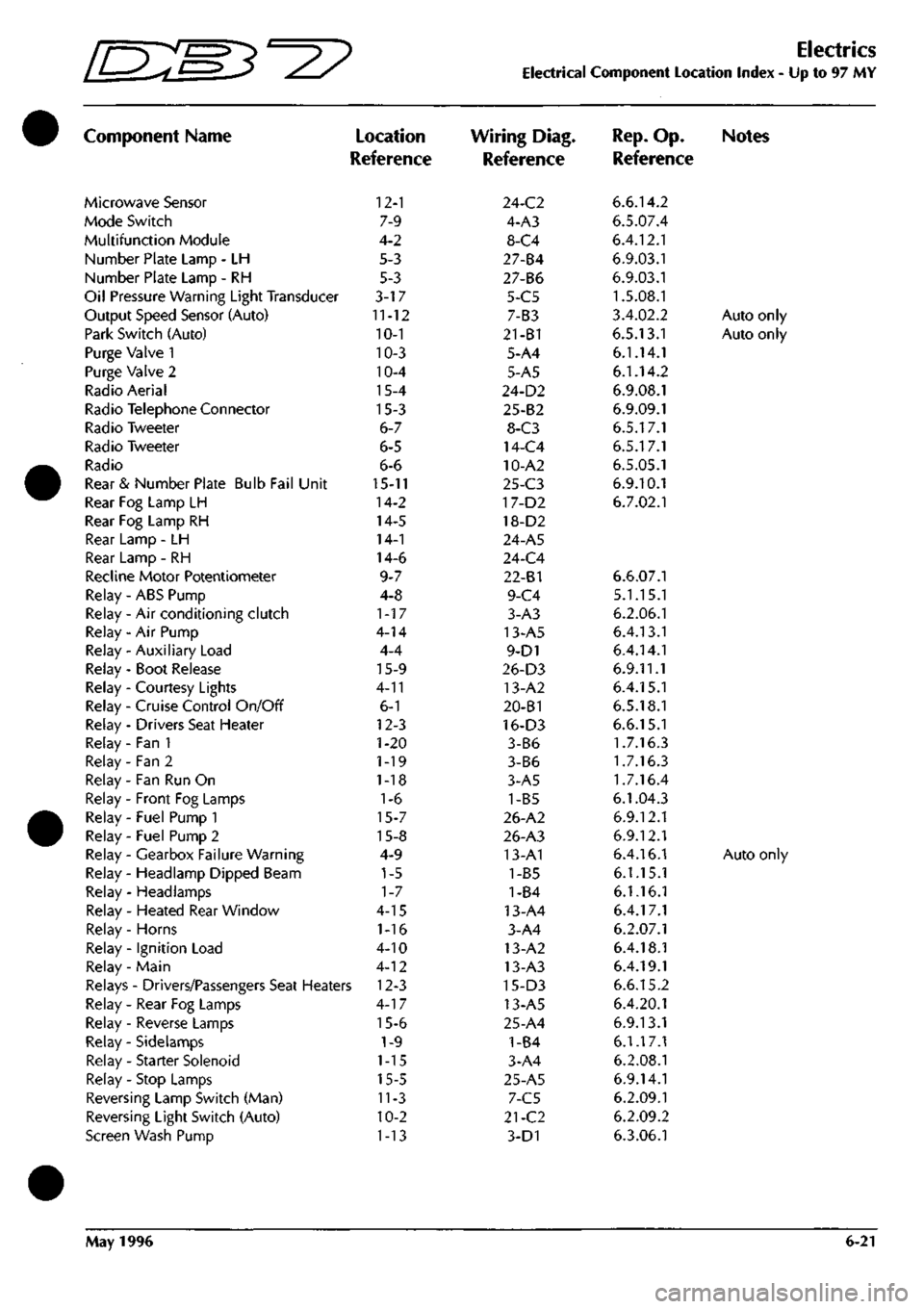
Component Name
Microwave Sensor
Mode Switch
Multifunction Module
Number Plate Lamp - LH
Number Plate Lamp - RH
Oil Pressure Warning Light Transducer
Output Speed Sensor (Auto)
Park Switch (Auto)
Purge Valve 1
Purge Valve 2
Radio Aerial
Radio Telephone Connector
Radio Tweeter
Radio Tweeter
Radio
Rear & Number Plate Bulb Fail Unit
Rear Fog Lamp LH
Rear Fog Lamp RH
Rear Lamp - LH
Rear Lamp - RH
Recline Motor Potentiometer
Relay - ABS Pump
Relay - Air conditioning clutch
Relay - Air Pump
Relay - Auxiliary Load
Relay - Boot Release
Relay - Courtesy Lights
Relay - Cruise Control On/Off
Relay - Drivers Seat Heater
Relay - Fan 1
Relay - Fan 2
Relay - Fan Run On
Relay - Front Fog Lamps
Relay - Fuel Pump 1
Relay - Fuel Pump 2
Relay - Gearbox Failure Warning
Relay - Headlamp Dipped Beam
Relay - Headlamps
Relay - Heated Rear Window
Relay - Horns
Relay - Ignition Load
Relay - Main
)
Location
Reference
12-1
7-9
4-2
5-3
5-3
3-17
11-12
10-1
10-3
10-4
15-4
15-3
6-7
6-5
6-6
15-11
14-2
14-5
14-1
14-6
9-7
4-8
1-17
4-14
4-4
15-9
4-11
6-1
12-3
1-20
1-19
1-18
1-6
15-7
15-8
4-9
1-5
1-7
4-15
1-16
4-10
4-12
Relays - Drivers/Passengers Seat Heaters 12-3
Relay - Rear Fog Lamps
Relay - Reverse Lamps
Relay - Sidelamps
Relay - Starter Solenoid
Relay - Stop Lamps
Reversing Lamp Switch (Man)
Reversing Light Switch (Auto)
Screen Wash Pump
4-17
15-6
1-9
1-15
15-5
11-3
10-2
1-13
Electrics
Electrical Component Location Index - Up to 97 MY
Wiring Diag.
Reference
24-C2
4-A3
8-C4
27-84
27-B6
5-C5
7-B3
21-B1
5-A4
5-A5
24-D2
25-B2
8-C3
14-C4
10-A2
25-C3
17-D2
18-D2
24-A5
24-C4
22-81
9-C4
3-A3
13-A5
9-D1
26-D3
13-A2
20-B1
16-D3
3-B6
3-B6
3-A5
1-B5
26-A2
26-A3
13-A1
1-B5
1-84
13-A4
3-A4
13-A2
13-A3
15-D3
13-A5
25-A4
1-B4
3-A4
25-A5
7-C5
21-C2
3-D1
Rep.
Op. Notes
Reference
6.6.14.2
6.5.07.4
6.4.12.1
6.9.03.1
6.9.03.1
1.5.08.1
3.4.02.2
Auto only
6.5.13.1
Auto only
6.1.14.1
6.1.14.2
6.9.08.1
6.9.09.1
6.5.17.1
6.5.17.1
6.5.05.1
6.9.10.1
6.7.02.1
6.6.07.1
5.1.15.1
6.2.06.1
6.4.13.1
6.4.14.1
6.9.11.1
6.4.15.1
6.5.18.1
6.6.15.1
1.7.16.3
1.7.16.3
1.7.16.4
6.1.04.3
6.9.12.1
6.9.12.1
6.4.16.1
Auto only
6.1.15.1
6.1.16.1
6.4.17.1
6.2.07.1
6.4.18.1
6.4.19.1
6.6.15.2
6.4.20.1
6.9.13.1
6.1.17.1
6.2.08.1
6.9.14.1
6.2.09.1
6.2.09.2
6.3.06.1
May 1996 6-21
Page 47 of 421
#
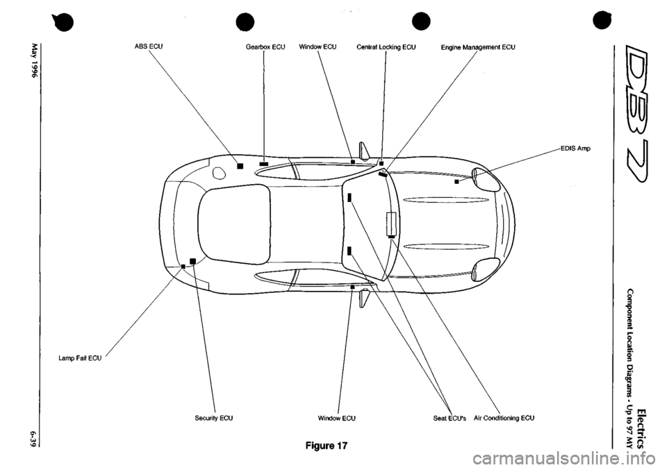
ABS ECU Gearbox ECU Window ECU Central Locking ECU Engine Management ECU
Lamp Fail ECU
EDIS Amp
Security ECU Window ECU Seat ECU'S Air Conditioning ECU
Figure 17
o
o 3 •a o 3 n 3 O n Si 5 3
ere
3
c
•o
o
-<
n
Page 69 of 421
NO
COLOUR
5
YS
14
WU
17
GW
51
RO
65
UB
70
YW
71
YB
83
WB
86
BK
90
GR
92
NR
94
RY
95
U
96
UW
97
GY
98
YP
99
YD
109
l.«S
121
WR
131
YR
136
UB
138
RN
163
BK
172
G
174
KB
198
GN
207
NB
209 OK 222
OS
226
BN
248 NS 250
WS
252
WY
253
UG
255
0
258
KB
259
OR
260 0 261
NR
262
BLG
321
PW
322
RU
323
GU
324
Y
325
LG
328
RN
330 YG 331
YU
351
WU
354
W
555
WR
362
RW
368 OS 369 OU 375
BY
377 8G 378 BS 379
BY
380 PG 381
BP
382
WB
383 K 384
WP
385 BU 386 60 387 CW 388 PS
AREA
C2 A5 A5 A5 A5 C4 C4 A5 B5
A5-97 A5-99
B5 B5 B5 B5 C4 04 B9 85 BS B5 B5 85 B5 B5 05 C5 C5 C5 C5 C5 C5
C4-93
C5 C5 C5 02 02 02 C5
A4-94
C5 C5 C5 C5 C5 C5 05 C6 C5 C5
C5 C5 C5
A5-98
05 05
A5-9e
OS 05 05 02 05
A5-I0C
86 B6 B6
NO
COLOUR
401
BY
402 WS 416
LOG
417
LGW
418
LGN
420 LGR 421
LG
422
LGP
423 BS 425
WP
433 P 435 WU 437 LG 438 W 439 W 445 NG 449 WK 451
1.G
455 GP 455 NP 457 NP 459 G 461
P
470 NU 471
BW
472
B
473 B 494 BR 498 P 505
LGO
510
B
522
YR
528
BK
536 B 537 W 551
B
552
B
555
W
565
B
566 NY 586 LGO 604 NB 608 0 616
P
618
B
622
KB
649 P 662 N 663 P 668 WO 687 NY 695 P 699 NU 710
R
712
W
714
WK
717
OU
718
OW
AREA
B6
A4-89
B6 B6 B6 B6 B6 B6 B6 B4 ez B2 B6 Be C4 B6 B6 86 B6 02 C4 D2 B6 B4 A2 A2 «2 C2 C2 02 85 C5 04 06 B6 86 86 86 B6 B6 B6 B6 B6 B6 B6 B6 C6 C6 C6 06 C6 C6 C6
45-96
C6
A4-94
C6
A4-90
-fl—«
SHEET
9
AREA
6
RADIO
SHEET
23
AREA
B2
SHEET
23
AREA
C2
REARWARD
REARWARD
rr
.
94 SPL 95
NO
COLOUi;
471
BW
472
B
475
B
474
YG
475
B
476
BR
477
BW
478
B
479
S
435 WU
435P
480 RK 481
B
48? BP
t>m 1 2 3 4 5 6 7 8 9 10 II 12 13
1*
~im Bl Bl Bl B2 B2 B2 66 Be 02 Al Al Be B2 B?
SPL
90
•N6
«Lot)R
PiN
482
BR
476
BR
483
LGK
484
RIN
485
WS
486
RN
487
GR
474
YC
488
BRD
481
B
475
B
489
UlN
490
R
491
W
1 2 '-^S 4 5 6 7 8 9 10 II 12 13 14 15
IS
AREA
B2 A2 C6 C6
A4-89
C6
A5-97
A2 C6 B2 A2 C6
A5-9e
CS
diQ]
IIDIIl
or
(DID
(DID
IT
r' '
IDDI
D) ID
k
4
1
5
(r
c
IDDl^
ID 01
QIIQ
ID
ffl^
4
8
NO
COLOUR
492
YW
493 KB
5
YS
261
NR
494 BR
495 OR 496 OU
PIN
2 3 4 5 6 7 S 9 10 II 12 IJ
AR^A'
C6 C6
Al
Bl Bl
C6 C6
NO
COLOW
497 SLG 498 P 499 PW 459 G 500 KB 259
OR
501
GB
383 K 455 NP 502
RU
503 BW 504
GW
260
0
505 LGO 506 OW 507 GP 508 OG
509
WK
479 S
175
PY
PIN 1 ? 3 4 5 6 7 8 9 10 11 1? 13 14 15 16 17 18 19 ?0 21 22 23
2<
AREA
C6 Bl
A4-94
Al 06 Bl
A4-92
CI Al ce C6 C6 81 Bl
A4-90
BS A4-91
A4-95
A2
85
SPL
96
SPL
98-
SUNROOF/ACC
NO
COLOUR
PIN
510
B 1
2 457 NP
3
511
WK 4
AREA
81
Al
A4-95
ABS
LOOM
|75
t^LOUtt
^IN
507
GP
512
WY
513
BY
514
RB
515
W
425
WP
516
BLG
1 2 3 4 5 e
I
AlitA
02 C6
A5-98
C6 C6 Al C6
'
(
EC
r
f
f=
IBIDl
(DID
Bjcnc
mm
m m
r
m
ml
7
13
1
14
SHEET
28
AREA
C3
ABS
LOOM
NO
COLOUR
PIN
445 NG 470 KU
AREA
Al
CRUISE CONTROL
NO
COLOUR
PIN
517
LGY 1
518
WY 2
519
GB 3
99
YO 4
98
YP 5
70
YW 6
71
YB 7
520
U
8
521
YU 9
522 YR
10
523
RW
11
524
B
12
525 BK
1?
AREA
C6
64-93 A4-92
Al Al Al Al C6 C6 Bl C6 C6 04
SHEET AREA
I
m
umti
14
WU
17
GW
51
RO
65
UB
83
WK
86
BK
94
RY
95
U
96
UW
97
GY
109
IGB
121
WR
131
YR
136
UB
138
RN
163
BK
172
G
174
KB
175
PY
198
GN
207
NB
209
OK
222
OS
226 BN 248
NS
250
WS
253
UG
255
G
258
KB
262
BLG
322 RU 323
GU
324
Y
325
LG
328
RN
330 YG 331
YU
351
WU
354
W
355
WR
362 RW 368 OS 369 OU 377
BG
378
BS
380 PG 381
BP
382
WB
384
WP
AREA
Al Al Al Al Al Al Al Al Al Al Al Al Bl Bl Bl Bl Bl Bl 02 Bl Bl Bl Bl Bl Bl Bl Bl Bl 61 Bl 81 81 Bl Bl CI CI CI CI CI CI
CI CI CI CI CI a CI CI CI
NO
COLOUR
386 GO 387 BW 388 PS 401
BY
416
LGG
417
LGW
416
LGH
420 LGR 421
LG
422
LGP
423
BS
437 LG 438 W 439 W
449WK
451
LG
453 GP 461
P
477
BW
478
B
480 RK 483 LGK 484 RIN 486 RN 488 BRD 489 UlN 491
R
492
YW
493 KB 495 OR 496 OU 497 SLG 500 KB 502
RU
503 BW 504 GW 512
WY
514
RB
515
W
516
BL6
517
LGY
520
U
521
YU
523
RW
524
B
526
BK
527
BK
536 B 557 W 540 NR
AREA
CI Al Al Al Al Al Al Al Al Al Al Al Al Al Al Al Al Bl A2 A2 B2 B2 B2 82 62 82 82 C2 C2 C2 C2 C2 D2 02 02 D2 85 B5 B5 BS C5 C5 C5 C6 C6 04 04 Bl Bl
A5-99
NO
COLOUR
542 GB 551
B
552
B
554
WY
555
W
563 BU 565
B
566 NY 574
WK
584
GR
586
LGO
587
WY
588 WS 595
BY
600 GB 603 NR 604 NB 608 0 615
BU
616
P
617
PW
618
6
622
KB
630 NR 646 GR 649 P 662 N 663 P 664 WK 668 WO 682
R
687 NY 688 OG 690 OW 695 P 699 NK 705
WK
712
W
716
PW
717
OU
mi
A4-92
61 Bl
B4-93
Bl
A5-10<
Bl Bl
A4-95 A5-97
ei
84-93 A4-89 A5-9S A4-92 A5-99
Bl Bl
A5-I0C
61
A4-94
CI CI
A5-99 A5-97
a CI CI
A4-95
CI
A5-9G
a
A4-9I A4-90
a a
A4-95
CI
A4-94
a
Emm
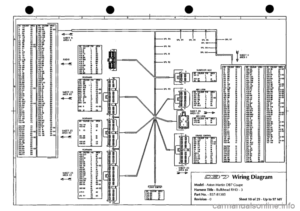
[D:m^-2? Wiring Diagram
Model
-
Aston Martin
DB7
Coupe
Harness Title
-
Bulkhead
RHD - 3
PartNo.-B37-81305
Revision
- 0
Sheet
10 of 29 - Up to 97 MY
Page 105 of 421

NO COLOUI 946 B 515 W 947 RY 94e BRD 949 BRP 950 BRO 951 BRD 952
YG
953
WG
954 WU 953
B
507 GP
956
WP
957
WN
958
WX
959 00 960 NS 512 *Y 961 RY
962 GIN 963 GIN 964 GIN 965 GIN 966 NK 967 RS
968 NU 969 GR 970 LGY 971 GW
PIN 1 2 3 4 5 6 7 8 9 10 II
12 13
14 15 16 17 18 19
20 21
22 23 24 25 26
27 28 29 30 31
3? 33 34
_a.
km Dl B3
CI-204
03 D4 02 B6 82 C6 B5 06 B3
C3-206
C6 C6 C6 C6 B3
01-204
D3 04 D2 C6 B2
CI-205
C4-207
C6 06 C6
Nfl
tiiivk fit) jRnr
Bl CI-205
_I!L
966 HK 974
RB
9"B
J.O.S.
CONNECTOR
•ROTSLOUSTTS
XREiT
984 NU I C4-207 aas B 2 C6
N(t 977 516 978 979 ?}t
COLOUR
PIN
B
1
BUG
2
PG
3
WP
4
WU
S
AR^ii
C6 B3 C6
C3-206
Al
NO COLOUR 972
B
952
YG
445 HG 976 B 975 RY
PIN 85 86 87 87A 30
AREA
Dl Al B3 C6
CI-204
ABS LOOM COLOUR PIN
NO
445 NG 470 NU
-JBET
B2 B4-207
NO 507 512 513 514 515 4?5 516
COLOUI
GP WY BY RB W IW> BLG
•RN
1 2 3 4 5 6
J.
AREA Al Al B6 CI-205 Al B3-206 BS
PUMP CONNECTOR ACCUMULATOR
ilo'
t6\.o\ik
Hu JSSET 982 B U C6
m>«i
w ti-;97
NO COLOUR 513
BY
951
BRD
95JWG 955 8 957
WN
958 WX 959 UG 960 NS 965 GIN 969 GR 970
LGY
971
GW
976 B 977 B 978
PG
982 B 985 B
>
titU
B3 Al Al Al Al Al Al Al Bl Bl 61 Bl 62 B5 85 C4 B4
NO COLOUR 946 B 972 B 973
B
AREA
Al B2 B2
REAR
L.H.SENSOR
REAR R.H. SENSOR FRONT L.H, SENSOR HO COLOUR PIN I 964 GIN 2 950 BRD 3
AREA NO COLOUR PIN I 962
GIN
2 946 BRD 5
NO COLOUR PIN
ASET
I 963 GIN 2 Bl 949 BRD 3 Al
Wiring
Diagram
Model
- Aston Martin DB7 Coupe
Harness
Title - ABS-1
Part
No. B37-81323
Revision
0 Sheet 28 of 29 - Up to 97 MY
Page 107 of 421

NO COLOUR 971 GW 958
WK
999 UG 969 GR 970 LCV 957 *N 953 8
PIN 1 2 3 4 5 6 ^
AREA Bl Bl Bl Bl Bl Bl Bl
NO COLOUF 976 B 9S7B 969 6
iRU CI AJ
B2-206
NO COLOUR AREA 513 Br 951 BRD 953 WO 955 8 957 WN 958 WK 959 UG 960 NS 965 GIN 969 GR 970
LGY
971 GW 976 B 977 B 978
PG
982
B
985 B
B5 C3 85 K K A2 A2 A3 C3 A2 A2 A2 B5 B2-208 85 B2-208 B5
NO COLOUR 953 WG 978 PO 988 B 515 BY
PIN 1 ? 3 4 5
AREA Al CI B2-208 Al
FRONT R.H. SENSOR NO COLOUR PIN !RE I 965
GIN
2 Bl 951 BRD 5 EL
Wiring Diagram
Model - Aston Martin DB7 Coupe
Harness Title - ABS-2
PartNo.-B37-81324
Revision - 0 Sheet 29 of 29 - Up to 97 MY
Page 108 of 421
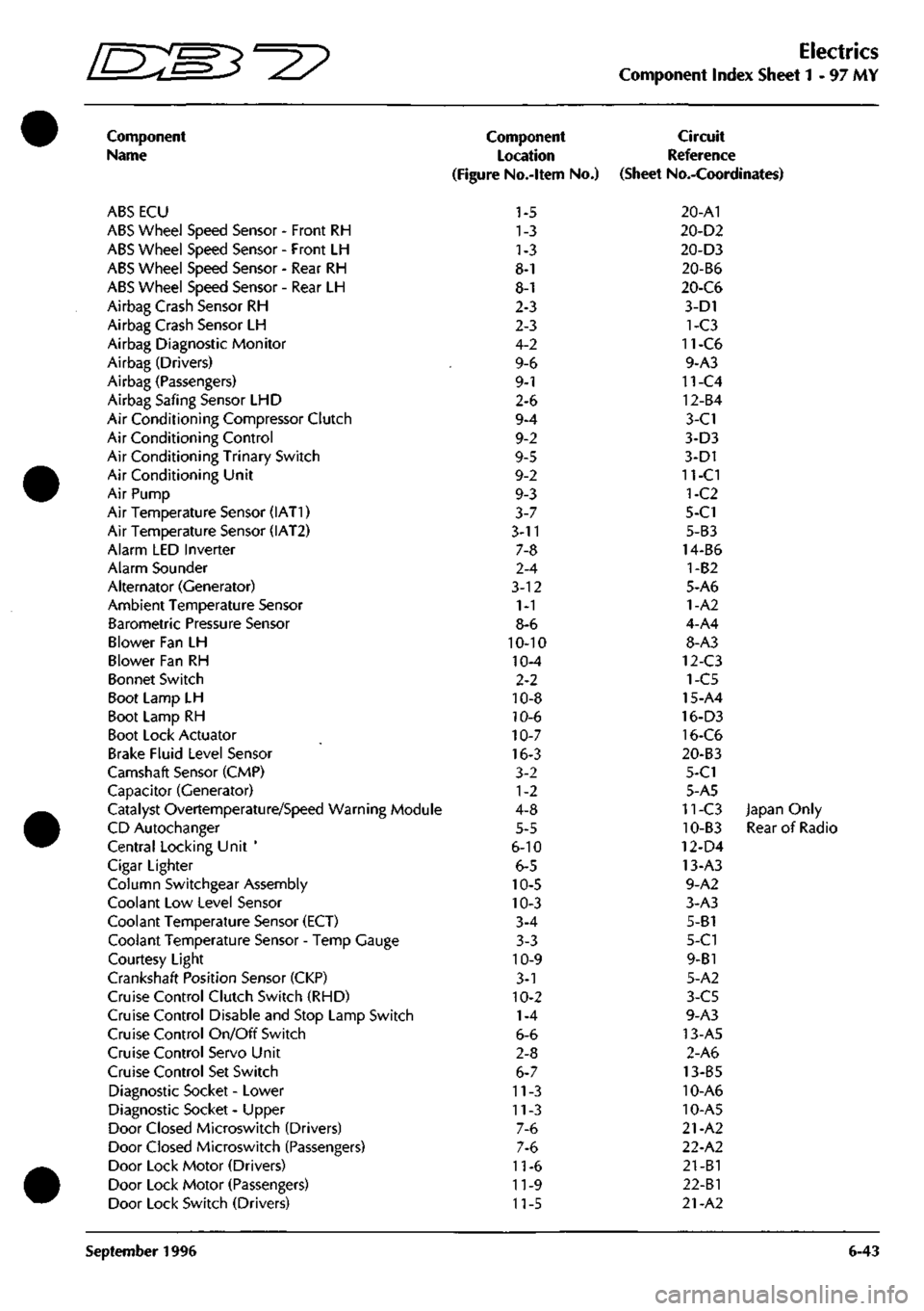
^7
Electrics
Component Index Sheet 1-97 MY
Component
Name
ABS ECU
ABS Wheel Speed Sensor - Front RH
ABS Wheel Speed Sensor - Front LH
ABS Wheel Speed Sensor - Rear RH
ABS Wheel Speed Sensor - Rear LH
Airbag Crash Sensor RH
Airbag Crash Sensor LH
Airbag Diagnostic Monitor
Airbag (Drivers)
Airbag (Passengers)
Airbag Safing Sensor LHD
Air Conditioning Compressor Clutch
Air Conditioning Control
Air Conditioning Trinary Switch
Air Conditioning Unit
Air Pump
Air Temperature Sensor (IAT1)
Air Temperature Sensor (IAT2)
Alarm LED Inverter
Alarm Sounder
Alternator (Generator)
Ambient Temperature Sensor
Barometric Pressure Sensor
Blower Fan LH
Blower Fan RH
Bonnet Switch
Boot Lamp LH
Boot Lamp RH
Boot Lock Actuator
Brake Fluid Level Sensor
Camshaft Sensor (CMP)
Capacitor (Generator)
Catalyst Overtemperature/Speed Warning Module
CD Autochanger
Central Locking Unit '
Cigar Lighter
Column Switchgear Assembly
Coolant Low Level Sensor
Coolant Temperature Sensor (ECT)
Coolant Temperature Sensor - Temp Gauge
Courtesy Light
Crankshaft Position Sensor (CKP)
Cruise Control Clutch Switch (RHD)
Cruise Control Disable and Stop Lamp Switch
Cruise Control On/Off Switch
Cruise Control Servo Unit
Cruise Control Set Switch
Diagnostic Socket - Lower
Diagnostic Socket - Upper
Door Closed Microswitch (Drivers)
Door Closed Microswitch (Passengers)
Door Lock Motor (Drivers)
Door Lock Motor (Passengers)
Door Lock Switch (Drivers)
Component
Location
(Figure No.-ltem No.)
1-5
1-3
1-3
8-1
8-1
2-3
2-3
4-2
9-6
9-1
2-6
9-4
9-2
9-5
9-2
9-3
3-7
3-11
7-8
2-4
3-12
1-1
8-6
10-10
10-4
2-2
10-8
10-6
10-7
16-3
3-2
1-2
4-8
5-5
6-10
6-5
10-5
10-3
3-4
3-3
10-9
3-1
10-2
1-4
6-6
2-8
6-7
11-3
11-3
7-6
7-6
11-6
11-9
11-5
Circuit
Reference
(Sheet No.-Coordinates)
20-A1
20-D2
20-D3
20-B6
20-C6
3-D1
1-C3
11-C6
9-A3
11-C4
12-B4
3-C1
3-D3
3-D1
11-CI
1-C2
5-C1
5-B3
14-B6
1-B2
5-A6
1-A2
4-A4
8-A3
12-C3
1-C5
15-A4
16-D3
16-C6
20-B3
5-C1
5-A5
11-C3 Japan Only
10-B3 Rear of Radio
12-D4
13-A3
9-A2
3-A3
5-B1
5-C1
9-B1
5-A2
3-C5
9-A3
13-A5
2-A6
13-B5
10-A6
10-A5
21-A2
22-A2
21-B1
22-Bl
21-A2
September 1996 6-43
Page 152 of 421
fj
NO COLOUR 636 N 655
N
704
N
7r7 N
AREA e.M S.A6 9.DI 9.04
UPPER SOCKET LOWER SOCKET
BATTERY
STUDt
NO COLOUR 786
N
787
N
788
N
AREA I0.AZ-I5I
8.B6-75
IO.BI-90
BATTERY
STUDt
NO COLOUR
PIN
AREA
760
ON
U
9.C4-85
761 GW W I0.B?-9I
SPL 151
-
^w^
SPL 89 SPL 90
T^
SUNROOF/ACC
NO COLOUR PIN AREA 762 B I
e.B4-67
2 658
NP
3 8.A6 660 WG 4 8.A6
II
[D
fl]
(D
01 ^5 4
ABS LOOM
RED
764
BY
726 RB 645 WR 765 0
AREA
A4/5
ABS
LOOM
BROWN
NO COLOUR
PIN
AREA 656
NG
I 8.A6
766 NO
2
II.A3 3
REARWARD HARNESS NO COLOUR 767 KB
338 OY 769 KB 3
YS
340 OC
771
BR
772 OR 773 OU
PIN 1 2 3 4 5 e
7 8 9 10 II 12 13
AREA I0.B4-I04
I2.BI I2.AI 8.AI 12.81
10.82-96
I0.C2-I00 IO.C3-I02
SHEET
14
AREA
B/CI
-4
«
NO COLOUR
PIN
AREA
774 YW 775 B
776
B
199
K
779 NS
I0.B2-92 I0.B3-IIO II.C4-II9
II.CI I0.B3-ID9
NO COLOUR
344 RIN 822 0 781 8 316 B
346 UIN
348 YU
785
NS
PIN
? 3 4 5 6 7 8 9 10 II 12 13 14 15 16
AREA
I2.A3 I0.D5 I0.B4-II0 I2.A3
I2.A3
I2.A3
10.84-109
'YD 0 0
D D
0
D
a
do DD pan Dap'
SPL 105 SPL 106 SPL 107
16/0 D
0
D
0 0
D
0\'
e/flDDODaODDo\'
SHEET
II
AREA
81
-SPL 97
-SPL 98
-
SPL 99
-
SPL 100
-
SPL 101
-
SPL 102
NO /89 790 791 792 793 794 795 796 797 643 641 798 799 800
COLOUf BW B B YG B BR BW B S
wu
p RK BR B
Pll 1 2 1 4 b 6
/
8 9 10 II 12 13 14
AREA
8.B4-66
8.B3-64
8.B2-63
IOCS I0.C5 I0.C5 I2.C3-14I I2.C2-I37 10.05 8.A4 8.A4 I0.B2-93 I0.C5 I0.C5
ILOGIC
EARTH
'
NO COLOUR AREA
1004 BK I0.B5-I0! 1005 BK I0.B2-95
(f
D
D
•
a
D
•
DOZL
D
D
0
D
0
D
•
D
D
D
DCT D
D
D
a
0
0 13 24
AREA
C/OI
REARWARD HARNESS NO COLOUF 803 SLG 804 PC 805 PW 667 G 1 LC 335 OR 807 GB 808 K 809 YN 621 RU 810 BW 811 GW 336 0 813 LGO 814 OW 815 GP 816 OG 294
R
652
WU
330 LCO 797
S
304
YB
337
RN
PIN 1 ? 3 4 5 6 7 8 9 10 II 12 13 14 15 16 17 18 19 20 21 22 23 24
AREA 11.03
e.B2-6l
8.83-65
8.A6 8.BI I2.AI I0.C2-I0I I2.A5 I2.A5 8.C4 10.62-94 I0.B2-9I
12.
Al
10.82-97 I0.B2-99 II.C2-II5 10,82-98 I2.AI 8.A4 I2.AI I0.B4
12.
Al
I2.AI
c
Q
D
n
n
D
CZ
u
u
D
D
D
0
SC:
D
D
D
D
n
n
3
CZ
u
u
D
D
REARWARD HARNESS NO COLOUf 799
BR
794
BR
724
LGK
736 RIN 327 RIN
823
GR
792 YG 824 SR 800 8 793 8 737 UIN 326 UIN 826
SW
827
R
828
BG
829
RN
374 0 723 LGS 822 0 177 YW
PIN 1 2 3 4 4 5 6 7 8 9 10 II 12 12 13 14 15 16 17 IB 19 20 21 22 23
AREA I0.B4 I0.B4 I2.CI 9.B4 I2.AI
9.C2-79
I0.B4 11.03 I0.B4 I0.D4 9.B4 I2.A1 11.03
9.C4-84
I0.B5-I06
9.C3-80
I0.B5-III I1.B3-I16 I0.A6 10.82-92
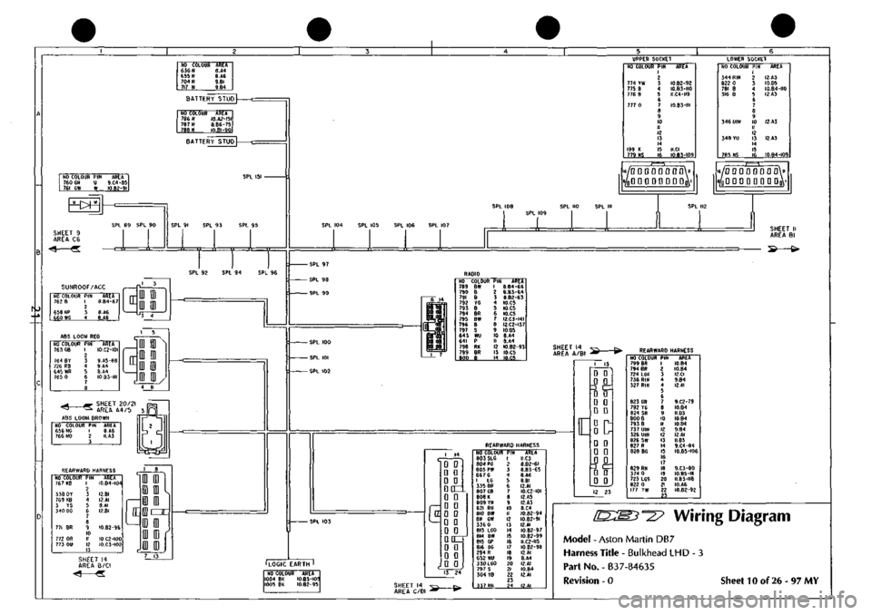
Wiring
Diagram
Model
- Aston Martin DB7
Harness
Title - Bulkhead LHD - 3
Part
No. - B37-84635
Revision
- 0
Sheet
10 of 26-97 MY
Page 172 of 421

NO COLOUI 766 NO 656 NG
1192 BU 1193 BG 1194 BO 1195 BY 1196 6R 1197 BK 1198 8W 1199 BS 1200 B 1201 B 645 m
763 GB 726 RB 1202 8
765 0
PIN 1 2 3 4 S 6 7 B 9 10 II 12 13 14 15 16 17 18 19 20 21 22 23 24 25 26 27 2B
AREA 20.A4 20.A4
20.03 20.03 20.02 20.02 20.C6 20.C6 20.B6 20.86 20.82 20.82 20.45
20.45 20.45 20.82
20.45
(^
NO
COLOUR
PIN
4RE4
656 NG
I 20.41
766 NO
2 20.41
3
SHEET
10 AREA^'i
NO 763
764 726 645 765
COLOUR
GB
BY RB m 0
PIN
1 2
3 4 5
6 7 8
ARE4
20.41
20.83
20.81 20.41 20.41
BULKHEAD SHOWN BULKHEAD
RED
NO
COLOUR
PIN
764
BY 1
1203
8 2
AREA 20.45 20.82
RESERVIOR SENSOR
HO
COLOUR
1200
8
1201
B
1202
B
1203
8
AREA
20.
Al
20.
Al
20.BI 20.83
J?;
^L
p[[CTJo
C3
CD CD en 5
A
CD CD CD C3 1
NO
COLOUR
PIN
AREA
I 1198
8W
2
1199
BS
3
20.
Al 20.41
REAR
R.H.
SENSOR
i
REAR
L.H.
SENSOR
NO
COLOUR
PIN
4REA
1196
BR
2
1197 BK
3
20.
Al
20.
Al
FRONT
R.H.SENSOR
FRONT
L.H.
SENSOR
NO
COLOUR
PIN
AREA
I 1194
80 2 20.41
1195
BY
3 20.41
NO
COLOUR
PIN
I 1192
8U
2
1193
BG
3
20.
Al 20.41
[D:m^-^ Wiring Diagram
Model - Aston Martin DB7
Harness Title-ABS-LHD
Part No. - B37-84645
Revision - 0 Sheet 20 of 26 - 97 MY
Page 232 of 421

Body and Trim
Body Repair ^^
Steel Body Parts - Repair^ Remove and
Replace
Removal
1.
Expose the resistance spot
weld.
For those spot
welds that are not obviously visible use a rotary
wire brush fitted to an air drill or a hand held wire
brush.
9.
Prepare the new panel joint edges for welding by
cleaning to bright metal, both interior and exterior
edges.
Apply weld through primer or inter-weld sealer to
all surfaces to be resistance spot welded.
Where appropriate, apply metal-to-metal adhesive
or sealer in accordance with the manufacturer's
instructions.
Caution: Do not
burn
off undersea I,
use a
'hot knife' or
a
suitable solvent.
2. Cut out the spot welds using aZipcutter or roto-Bor.
At this point it may be necessary to cut out the bulk
of a panel using a pneumatic saw.
Note: On
some
panels,
before removing the bulk of the
panel, brazed
areas
and MIC welded
seams
should be
removed.
3. Separate the spot welded joints and remove the
panel remnants.
Preparing Old Surfaces
1.
Remove the weld nuggets with a sander and 36 grit
disc.
2.
Clean all flanges to a bright smooth finish.
3. Straighten existing panel joint edges as required.
Preparing New Surfaces
1.
Mark off the area of the new panel and cut to size
leaving approximately two inches overlap on the
existing panel
2.
Offer up the new panel or section and align it with
the associated parts.
3. Clamp the panel into position.
4.
Where necessary, cut the new and original panels
to form a but joint.
5. Remove all clamps and the new panel.
6. If required, apply the inner panel protection and or
sound insulation.
Panel Alignment
1.
Align the replacement panel with the associated
panel and clamp it in position.
2.
With certain panels it may be necessary to tack
weld or use PK screws.
Welding
1.
MIC tack the butt joints.
2.
Re-check the alignment and the panel contours as
necessary.
3. Select the correct arms for resistance spot welding
and ensure that the tips are correctly trimmed.
Note: It
is
recommended that
the arms are
not more than
12 in (300 mm) in length.
4.
Test the equipment for satisfactory operation using
test coupons.
In the absence of test equ ipment
a
satisfactory weld
can be verified by pulling the test coupons apart
and viewing the welded condition.
5. Resistance spot weld where required. Note the
presence of zinc coated panels and treat as
previously described.
6. Dress back all MIC tack welds.
7. MIG seam weld the butt joints.
8. Dress all welds as required.
9. Final brazeand lead load as necessary priorto paint
preparation.
7-4 May 1996