check engine ASTON MARTIN DB7 1997 Workshop Manual
[x] Cancel search | Manufacturer: ASTON MARTIN, Model Year: 1997, Model line: DB7, Model: ASTON MARTIN DB7 1997Pages: 421, PDF Size: 9.31 MB
Page 5 of 421
//—-^
^^^^5~^
' -^ ^ Introduction
Safety Precautions
Safety Precautions (continued)
Electrical Equipment
1.
Ensure that electrical equipment is in safe working order before use.
2.
Inspect power leads of all mains electrical equipment for damage and security, and check that it is properly
earthed.
3. Ensure that electrical equipment is protected by a fuse of the correct current rating.
4.
Disconnect the battery before commencing repair operations to the electrical system, fuel system and engine
or when working beneath the vehicle.
Exhaust Fumes
Engines should not be run in confined spaces, exhaust fumes contain harmful and toxic substances including carbon
monoxide which can prove fatal if inhaled. Engines must only be run where there is fume extraction equipment in
operation or where there is adequate ventilation.
Fire Precautions
1.
Ensure that a suitable form of fire extinguisher is conveniently located near the work area.
2.
Keep oils, solvents and combustible materials away from naked flames and other sources of ignition.
3. Ensure that NO SMOKING signs are posted around areas where combustible materials and vapour may be
present and ensure that the warnings are strictly observed.
4.
Ensure that dry sand is available to soak up any spillage of fuel or other flammable solutions.
5. Fume extraction equipment must be available and in full working order to remove combustible and toxic
vapours.
6. All personnel should be aware of the fire drill procedures and precautions.
Jacking and Lifting
1.
The recommended procedures for lifting, jacking and towing are included latefin this seetion-and must be
strictly observed to ensure personal safety.
2.
Always use a vehicle hoist, ramp or pit for working beneath the car in preferencetd^&^cking
3. Never rely on a jack to support a car independently, use axle stands or blocks carefully pJaQed at the jacking
points to provide rigid support.
4.
When working beneath a vehicle, chock the wheels as well as applying the handbrake.
5. Ensure that the vehicle is standing on firm level ground before jacking or lifting.
5. Check any lifting equipment used has adequate capacity for the load being lifted and is ih"fdll working order.
Tools and Equipment
1.
Do not leave tools, equipment, spilt oil, etc. around or on the work area.
2.
Ensure that tools and equipment used are in good condition; do not use damaged or defective tools or
equipment.
3. Do not apply heat in an attempt to free stiff nuts or fittings; as well as causing damage to protective coatings,
there is a risk of damage to electronic equipment and brake lines from stray heat.
4.
Use the recommended service tool where instructed to do so.
April 1997 v
Page 187 of 421
^=2?
Electrics
Airbag System
Eye Protection
Chemical protective goggles are recommended
where there is a possibility of eye contact with the
propellant. Safety glasses with side shields are
recommended for all other operations.
Protective Clothing
Approved protective gloves, overalls and shoes/
boots should be worn.
Handling and Storage Precautions
Do not store airbag modules near live electrical
equipment or circuitry. Store in a dry environment
at ambient temperatures.
Good housekeeping and engineering practices
should be employed to prevent the generation and
accumulation of
dusts.
Store in compliance with all
local state and federal regulations.
Driver and Passenger Airbag Modules
Assembly/Removal/Service Instructions
WARNING: In the event of a vehicle impact where the
airbags and the seatbeltpretensioner (if fitted) are
deployed, the following actions MUST be
performed:
Check the condition of the seatbelts, steering
wheel,
steering column, all connections to airbags,
and the column switchgear connectors for integrity
and damage. If in any
doubt,
replace suspected
parts for new parts.
Replace both crash
sensors,
the
safing sensor
and
the seatbelt pretensioner module (if fitted).
On completion of all repair procedures, switch on
the ignition and check that the
Airbag/SRS
warning
light comes on when the ignition is switched on
and extinguishes after approximately six seconds
indicating satisfactory completion of the airbag
and pretensioner
system
self
tests.
WARNING: Before starting
work,
ensure
that the ignition
switch is in position 'O' and the ignition key is
removed.
Disconnect the battery negative lead
within 12 seconds of switching off the ignition to
prevent the alarm system triggering.
As the airbag control module is equipped with a
back-up power source and due to the risk of the
airbag being inadvertently deployed, wait one
minute or longer after disconnecting the battery
before starting work on the airbag module.
• Disconnectingthe battery negative cable cancels
the memory for the 'one-touch' window down
system and stops the vehicle clock. Reset the
window memory and the clock when work is
completed.
• Never use airbags from other vehicles, always
use new parts.
• After work is completed, reconnect the battery
and perform the airbag warning light check
• Never use electrical probes to check voltage or
electrical resistance of the airbag modules.
• Disconnect the airbag before carrying out any
work on, or in the vicinity of the module, or
when using electric welding equipment.
• Always ensure that the battery negative lead has
been disconnected for at least one minute before
commencing any removal procedure.
September 1996 6-71
Page 204 of 421
Electrics
Airbag System [D:B3-2?
Airbag DM Fault Code 22
Safing sensor output circuit shorted to battery
voltage.
Normal Operation
The diagnostic module measures the voltage at pin
2-5 (airbag module feed) and 2-5 (safing sensor
output monitor) at thediagnosticmoduleconnector.
The voltage at these pins is dependant on charging
system voltage as shown in the table below. If the
voltage at either pin exceeds 5 volts,
a
fault code 22
will be generated.
in 2-5
2.3V
2.4V
2.5V
2.7V
2.8V
3.0V
3.1V
3.2V
3.4 V
3.5V
3.7V
3.8V
4.0V
4.1V
4.3V
Pin 2-6
2.3V
2.4V
2.5V
2.7V
2.8V
3.0V
3.1V
3.2 V
3.4 V
3.5V
3.7V
3.8V
4.0V
4.1V
4.3V
Charge Volts
9.0V
9.5V
10.0V
10.5V
11.0V
11.5V
12.0V
12.5V
13.0V
13.5V
14.0V
14.5V
15.0V
15.5V
16.0V
Possible Causes
• A short between pins 2-5 or 2-6 and another
wire.
(The wiring to the safing sensor carries
voltages above 5 volts).
• A short between the cable reel cassette circuit
and other 12 volt circu its at the steering column
head.
• A short across the normal ly open contacts of the
safmg sensor.
• Vehiclechargingsystem voltage too
high.
If the
generator output is greater than 17V, fault code
22 may be logged.
Fault Analysis
WARNING: Read and adhere to all warnings and
safety procedures at the start of this section when
working on the airbag system.
Disarm the airbag system and fit airbag simulators
(6.4.21.4).
Check the voltage at the battery with the engine
running at approximately 1500 rpm.
If the voltage is 14.8 ±0.5 volts, the charging
voltage is within specification, go to step 3.
If the voltage is significantly above 14.8 volts (the
voltage regulator set point) service the charging
system.
Clear the code 22. Rearm the airbags
(6.4.21.4)
Check in the area of the diagnostic module
connector for harness damage which could cause
a short circu it to 12 volts. (Note: The airbag system
harness runs are sheathed in black plastic protection
and harness damage is unlikely.)
If no harness damage is evident, go to step 4.
If harness damage is identified, service the wiring as
necessary. Clear the code 22. Rearm the airbags
(6.4.21.4).
Switch on the ignition. Monitor the voltage at pins
2-5 and 2-6 whilst rotatingthe steering from lock to
lock in both directions.
If the voltage at both pins remains below 5.0 volts,
go to step 5.
If the voltage rises to above 5.0 volts, service the
cable reel cassette or wiring as necessary. Clear the
code 22. Rearm the airbags (6.4.21.4).
With the ignition on, check the voltage at pins 2-5
and 2-6 whilst manipulating the bulkhead and
safing sensor harnesses.
If the voltage rises above 5.0 volts, service the
wiring fault in the harness area being manipulated
at the time the voltage rise occurred.
If no voltage rise occurs, fit a new safing sensor as
the most likely cause of the code 22. Clear the code
22 and rearm the airbags (6.4.21.4).
6-88 September 1996
Page 206 of 421
Electrics
Airbag System =2?
Airbag DM Fault Code 24
Safing sensor output - battery feed/return open
circuit.
Normal Operation
The diagnostic module measures the voltage on
diagnostic module pins 2-5 and 2-6 the voltage
varies with the vehicle charge level
as
shown in the
table below:
in 2-5
2.3V
2.4 V
2.5V
2.7V
2.8V
3.0V
3.1V
3.2V
3.4V
3.5V
3.7V
3.8V
4.0V
4.1V
4.3V
Pin 2-6
2.3V
2.4V
2.5V
2.7V
2.8V
3.0V
3.1V
3.2V
3.4V
3.5V
3.7V
3.8V
4.0V
4.1V
4.3V
Cliarge Volts
9.0V
9.5V
10.0V
10.5V
11.0V
11.5V
12.0V
12.5V
13.0V
13.5V
14.0V
14.5V
15.0V
15.5V
16.0V
The diagnostic module also measures the voltage at
pin 1-7 (battery input). Using the battery input
voltage, the system can predict the expected voltage
level on pins 2-5 and 2-6. If the voltage on pins 2-
5 or 2-6 is higher or lower than expected, a fault
code 24 will be declared.
Possible Causes
• Open circuit or high resistance in the wiring
harness or safing sensor.
• Intermittent battery voltage on pin 1-7
• The resistance of the pin 2-5 to 2-6 circuit to
ground.
This circuit should be open to ground at
all times.
Fault Analysis
WARNING: Read and adhere to all warnings and
safety procedures at the start of
this
section when
working on the airbag system.
1.
Disarm the airbag system and fit airbag simulators
(6.4.21.4).
2.
Probe the battery input voltage terminal
1
-7. Start
the engine and monitor the charge voltage level
using a digital multimeter. Run the engine at idle
speed and look for any instability in the voltage
level.
Run the engine at a constant medium speed
and then at a constant high speed and repeat the
observation for voltage instability.
If the voltage levels are stable, go to step 3.
If instability of the voltage level is observed,
Investigate and rectify the problem in the charging
circuit.
3. Switch off the ignition. Disconnect the diagnostic
module and check for OQ continuity from pins 2-5
to 2-6.
If no resistance is detected, go to step 4.
If any resistance is detected between pins 2-5 and
2-6,
service the wiring or safing sensor to achieve
Ofi continuity.
4.
Measure the resistance to ground from pins 2-5 and
2-6.
If no short circuit is detected, replace the diagnostic
monitor. Rearm the airbags (6.4.21.4).
If
a
short to grou
nd
is detected, service the wiring or
safing sensor as necessary. Rearm the airbags
(6.4.21.4).
6-90 September 1996
Page 282 of 421
Em^^^?
Air Conditioning
General Description
General Description
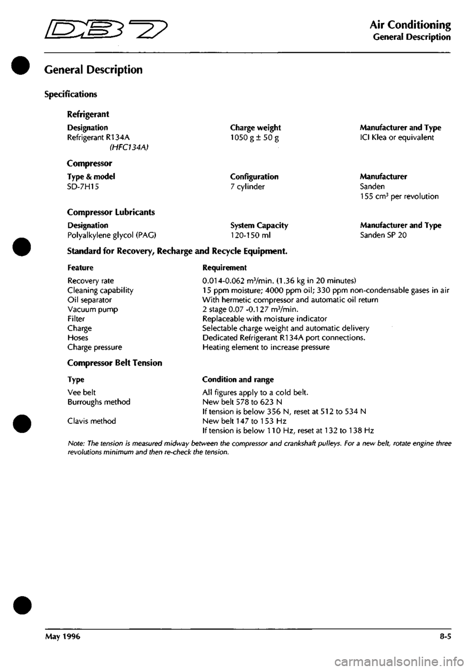
Specifications
Refrigerant
Designation
Refrigerant R134A
(HFCUAA)
Compressor
Type
&
model
SD-7H15
Charge weight
1050g±50g
Configuration
7 cylinder
Compressor Lubricants
Designation
Polyalkylene glycol
(PAG)
Standard
for
Recovery, Recharge
and
Recycle Equipment,
System Capacity
120-150
ml
Manufacturer and Type
ICI Klea
or
equivalent
Manufacturer
Sanden
155 cm^
per
revolution
Manufacturer and Type
Sanden SP
20
Feature
Recovery rate
Cleaning capability
Oil separator
Vacuum pump
Filter
Charge
Hoses
Charge pressure
Compressor Belt Tension
Type
Vee belt
Burroughs method
Clavis method
Requirement
0.014-0.062
mVmin.
(1.36 kg in 20
minutes)
15
ppm
moisture; 4000
ppm oil; 330 ppm
non-condensable gases
in air
With hermetic compressor and automatic
oil
return
2 stage
0.07
-0.127 mVmin.
Replaceable with moisture indicator
Selectable charge weight and automatic delivery
Dedicated Refrigerant R134A port connections.
Heating element
to
increase pressure
Condition and range
All figures apply
to a
cold belt.
New belt
578 to 623 N
If tension
is
below
356 N,
reset
at 512 to 534 N
New belt
147 to 153 Hz
If tension
is
below
110 Hz,
reset
at 132 to 138 Hz
Note:
The
tension
is
measured
midway between the
compressor
and crankshaft pulleys. For a new
belt,
rotate engine three
revolutions minimum and then re-check the tension.
May 1996
8-5
Page 292 of 421
Air Conditioning
Functional Check
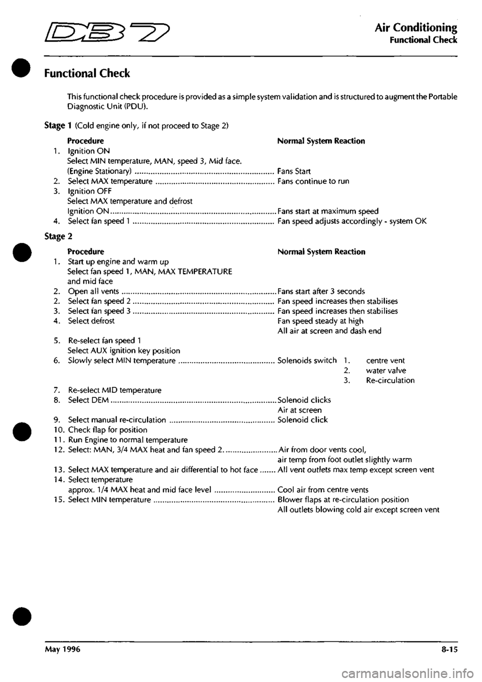
Functional Check
This functional check procedure is provided as a simple system validation and is structured to augment the Portable
Diagnostic Unit (PDU).
Stage 1 (Cold engine only, if not proceed to Stage 2)
Procedure Normal System Reaction
1.
Ignition ON
Select MIN temperature, MAN, speed 3, Mid face.
(Engine Stationary) Fans Start
2.
Select MAX temperature Fans continue to run
3. Ignition OFF
Select MAX temperature and defrost
Ignition ON Fans start at maximum speed
4.
Select fan speed
1
Fan speed adjusts accordingly - system OK
Stage 2
Procedure Normal System Reaction
1.
Start up engine and warm up
Select fan speed 1, MAN, MAX TEMPERATURE
and mid face
2.
Open all vents Fans start after 3 seconds
2.
Select fan speed 2 Fan speed increases then stabilises
3. Select fan speed 3 Fan speed increases then stabilises
4.
Select defrost Fan speed steady at high
All air at screen and dash end
5. Re-select fan speed 1
Select AUX ignition key position
6. Slowly select MIN temperature Solenoids switch 1. centre vent
2.
water valve
3. Re-circulation
7. Re-select MID temperature
8. Select DEM Solenoid clicks
Air at screen
9. Select manual re-circulation Solenoid click
10.
Check flap for position
11.
Run Engine to normal temperature
12.
Select: MAN, 3/4 MAX heat and fan speed 2 Air from door vents
cool,
air temp from foot outlet slightly warm
13.
Select MAX temperature and air differential to hot face All vent outlets max temp except screen vent
14.
Select temperature
approx. 1/4 MAX heat and mid face level Cool air from centre vents
15.
Select MIN temperature Blower flaps at re-circulation position
All outlets blowing cold air except screen vent
May 1996 8-15
Page 293 of 421
Air Conditioning //—^ ^ci^^ • ^ ^
Fnnrtlnn;il fhprk I *-/ -^ r <
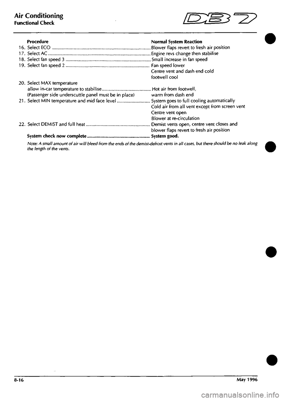
Procedure Normal System Reaction
16.
Select ECO Blower flaps revert to fresh air position
17.
Select AC Engine revs change then stabilise
18.
Select fan speed 3 Small increase in fan speed
19.
Select fan speed 2 Fan speed lower
Centre vent and dash end cold
footwell cool
20.
Select MAX temperature
allow in-car temperature to stabilise Hot air from footwell,
(Passenger side underscuttle panel must be in place) warm from dash end
21.
Select MIN temperature and mid face level System goes to full cooling automatically
Cold air from all vent except from screen vent
Centre vent open
Blower at re-circulation
22.
Select DEMIST and full heat Demist vents open, centre vent closes and
blower flaps revert to fresh air position
System check now complete System good.
Note: A small amount of air will bleed from the
ends
of the
demist-defrost vents
in all
cases,
but there should be no leak along
the length of the vents.
8-16 May 1996
Page 311 of 421
Air Conditioning
Refrigeration /s:s^°27
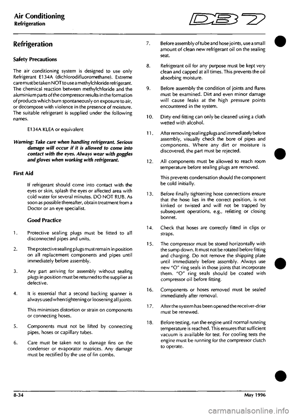
Refrigeration
Safety Precautions
The air conditioning system is designed to use only
Refrigerant E134A (dichlorodifluoromethane). Extreme
care must betaken NOT to use
a
methylchloride refrigerant.
The chemical reaction between methylchloride and the
aluminium parts ofthe compressor results in the formation
ofproductswhich burn spontaneously on exposure toair,
or decompose with violence in the presence of moisture.
The suitable refrigerant is supplied under the following
names.
El 34A KLEA or equivalent
Warning: Take care when handling refrigerant. Serious
damage will occur if it is allowed to come into
contact with the eyes. Always wear with goggles
and gloves when working with refrigerant
First Aid
If refrigerant should come into contact with the
eyes or
skin,
splash the eyes or affected area with
cold water for several minutes. DO NOT RUB. As
soon as possible thereafter, obtain treatment from a
Doctor or an eye specialist.
Good Practice
1.
Protective sealing plugs must be fitted to all
disconnected pipes and units.
2.
Theprotectivesealingpiugsmustremain inposition
on ail replacement components and pipes until
immediately before assembly.
3. Any part arriving for assembly without sealing
plugs in position must be returned to the supplier as
defective.
4.
It is essential that a second backing spanner is
always used when tightening or loosening all joints.
This minimises distortion or strain on components
or connecting hoses.
5. Components must not be lifted by connecting
pipes,
hoses or capillary tubes.
6. Care must be taken not to damage fins on the
condenser or evaporator matrices. Any damage
must be rectified by the use of fin combs.
7. Before assembly oftube and hosejoints, use
a
small
amount of clean new refrigerant oil on the sealing
seat.
8. Refrigerant oil for any purpose must be kept very
clean and capped at all times. This prevents the oil
absorbing moisture.
9. Before assembly the condition of joints and flares
must be examined. Dirt and even minor damage
will cause leaks at the high pressure points
encountered in the system.
10.
Dirty end fitting can only be cleaned using a cloth
wetted with alcohol.
11.
Afterremovingsealingplugsand immediatelybefore
assembly, visually check the bore of pipes and
components. Where any dirt or moisture is
discovered,
the part must be rejected.
12. Ail components must be allowed to reach room
temperature before sealing plugs are removed.
This prevents condensation should the component
be cold initially.
13.
Before finally tightening hose connections ensure
that the hose lies in the correct position, is not
kinked or twisted and will not be trapped by
subsequent operations, e.g., refitting or closing
bonnet.
14.
Check that hoses are correctly fitted in clips or
straps.
15.
The compressor must be stored horizontally with
the sump down. It must not be rotated before fitting
and charging. Do not remove the shipping plate
until immediately before assembly. Always use
new "O" ring seals in those joints that incorporate
them.
"O" ring seals should be coated with
compressor oil before fitting.
16.
Components or hoses removed must be sealed
immediately after removal.
1 7. Afterthe system has been opened the receiver-drier
must be renewed.
18.
Before
testing,
run the engine until normal running
temperature is reached. This ensures that sufficient
vacuum is available for test. For cooling tests the
engine must be running for the compressor clutch
to operate.
8-34 May 1996
Page 316 of 421
^=2?
Air Conditioning
System Checking with the Manifold Gauge Set
System Checking with the Manifold
Gauge Set
Connecting the Manifold Gauge Set
Caution: Only use hoses with connectors which are
dedicated to HFC 134A charge ports.
Attachmentofthehosequick release connectors to
the high and low side
system
ports
is
straightforward,
provided that the high and low valves are closed
and the system is NOT operational.
Assessment ofthe system's operating system can be
carried out by using the facilities ofthe Recovery-
Recharging-Recycling station. Follow the
manufacturer's instructions carefully and closely
observe the safety procedures.
Warning: Under no circumstances should the connections
be made with the
system
in operation or the
valves
open. Should the valves be open and a vacuum
pump or refrigerant container attached, an
explosion could occur
as
a result of high pressure
refrigerant being forced back into the vacuum
pump or container.
Stabilising the System
Accurate test gauge data can be attained only if the
system temperatures and pressures are stabilised.
Ensure that equipment and its hoses cannot come
into contact with moving parts or heat sources.
It is recommended that a free standing air mover is
placed in front of the vehicle to provide mass air
flow through the condenser-cooling system.
Checking Procedure
Connecting the Gauge Set.
A test hose connected to the fitting directly under
the low side gauge is used to connect the low side
ofthe test manifold into the low side ofthe system,
and a similar connection is found on the high side.
When connecting the gauge manifold set to the air
cond ition i ng system an access va Ive core removi ng
tool is available for connecting the test hoses to the
high and low sides ofthe system.
Using the valve removing tool it enables the valve
core to be removed and held back inside the tool
eliminating restrictions and, thereby, providing a
full flow of refrigerant.
Warning: Do not open the high side hand valve while the
air conditioning system is in operation because,
high pressure refrigerant will be forced through
the high side gauge and to the refrigerant container,
if it is attached.
This
could cause the container to
rupture or the fitting at the safety container valve
to burst resulting in damage and personal injury.
1.
With theengineswitched off, remove the protective
caps from the schraeder valves.
2.
Fit the access valve removal tool to the schraeder
valves. Ensure that both the manifold hand valves
are in the closed position.
3. Connect the high pressure manifold gauge hose (to
the high pressure side of the air conditioning side of
the system (high side is always the line from the
compressor to the condenser). Connect the low
pressure or compound gauge hose to the low
pressure side ofthe air conditioning system.
4.
Using the access valve removal tool loosen and
screw out the valve cores.
1.
Start the engine and allow it to attain normal
working temperature then set it at fast idle (typically
1200 to ISOOrpm).
2.
Select full air conditioning performance.
3. With all temperatures and pressures stable or
displaying symptoms of faults, begin relevant test
procedures.
May 1996 8-39
Page 317 of 421
Air Conditioning
System Checking with the Manifold Gauge Set D'^?
Purging the Test Hoses
1.
With the manifold test set attached to the system.
2.
Purge the high pressure test hose by cracking open
the high pressure side hand valve on the manifold
gauge set for 3 to 5 seconds. This allows the system
refrigerant to purge the air from the test hose and
discharge through the manifold centre test hose.
Immediately cl ose the high pressure side hand
valve.
3. Purge the low pressure test hose in the same manner
by cracking open the low pressure side hand valve
manifold gauge
set
for 3 to 5 seconds, then close the
hand valve.
Stabilising the System
The manifold gauge set is now attached to the
system and the test hoses purged of air. With both
hand valves closed, the system must be operated
for a few minutes to stabilise all pressures and
temperatures throughout the system in order to
obtain accurate test gauge readings.
Proceed as follows:
1.
Place all test hoses, gauge set and other equipment
away from all engine moving parts. Also keep the
hoses from touching the hot engine manifold.
2.
Start the engine and adjust engine speed to fast idle
3. Turn on the air conditioning and set for maximum
cooling with blower fans on high speed
4.
Open the car doors and/or windows (to quickly
eliminate car interior heat).
5. Operate the system under these conditions for 5 to
10 minutes to stabilise the system ready for testing.
6. Check the system for full refrigerant by noting the
sightglass indications. Some refrigerant loss occurs
over a period of time.
Note: The air conditioning
system
must contain a full
refrigerant
charge
before an accurate
system
check can
be
made.
An insufficient
charge
is indicated by
a stream
of
bubbles
or
foam.
If
the
refrigerant charge is low, the
system
must
be
fullydischarged into
a
refrigerant recovery
station and recharged with the correct weight of refrigerant
82.30.08. Do not top up a
system
with refrigerant.
Leak Test
A high proportion of ail air conditioning work
consists of locating and repairing leaks.
Many leaks are located at connections and are
caused by vibration. They may only require the re-
tightening of a connection or clamp.
Occasionally a hose rubs on a structural part of the
vehicle and creates a leak, or a hose deteriorates
which will require a replacement.
The specified maximum leakage rate at each fitting
is 0.5 kg of R 134a in 40 years and a leak detector
capable of operating to this accuracy must be
provided.
To check place the leak detector probe at
the lowest pointofeach joint, pausefortwo seconds.
Do not wave the probe about as refrigerant is
heavier than air and flows to the lowest point. If a
leak is greater than 0-5 kg in forty years is detected
identify the leak point for rectification.
Check that the leaking fitting has been tightened to
the correct torque. If the torque is low, rectify and
repeat leak test. If the torque is satisfactory,
depressurise the system, dismantle the leaking
connection and check the quality of the fitting.
If the fitting is satisfactory, clean and reassemble
after applying a thin film of refrigerant to the seat of
aflarefitting, ora newoiled "O" ring to an "O" ring
fitting.
Tighten to the correct torque.
Charge the system with 200 g of El 34A and leak test
the rectified system. If the system is satisfactory,
depressurise, evacuate and recharge the system.
If the system is unsatisfactory, i.e. leakage greater
than 0.5 kg in forty years, depressurise and replace
the leaking assembly.
8-40 May 1996