clutch ASTON MARTIN DB7 1997 Workshop Manual
[x] Cancel search | Manufacturer: ASTON MARTIN, Model Year: 1997, Model line: DB7, Model: ASTON MARTIN DB7 1997Pages: 421, PDF Size: 9.31 MB
Page 27 of 421
Electrics
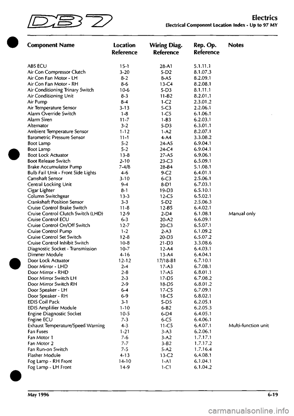
Electrical Component Location Index - Up to 97 MY
Component Name
ABS ECU
Air Con Compressor Clutch
Air Con Fan Motor - LH
Air Con Fan Motor - RH
Air Conditioning Trinary Switch
Air Conditioning Unit
Air Pump
Air Temperature Sensor
Alarm Override Switch
Alarm Siren
Alternator
Ambient Temperature Sensor
Barometric Pressure Sensor
Boot Lamp
Boot Lamp
Boot Lock Actuator
Boot Release Switch
Brake Accumulator Pump
Bulb Fail Unit - Front Side Lights
Camshaft Sensor
Central Locking Unit
Cigar Lighter
Column Switchgear
Crankshaft Position Sensor
Cruise Control Brake Switch
Cruise Control Clutch Switch (LHD)
Cruise Control ECU
Cruise Control On/Off Switch
Cruise Control Pump
Cruise Control Set Switch
Cruise Control Inhibit Switch
Diagnostic Socket - Transmission
Dimmer Module
Door Lock Actuator
Door Mirror- LHD
Door Mirror- RHD
Door Mirror Switch LH
Door Mirror Switch RH
Door Speaker -LH
Door Speaker - RH
EDIS Coil Pack
EDIS Amplifier Module
Engine Diagnostic Socket
Engine ECU
Exhaust Temperature/Speed Warning
Fan Fuses
Fan Motor 1
Fan Motor 2
Fan Run-on Switch
Flasher Module
Fog Lamp - RH Front
Fog Lamp - LH Front
Location
Reference
15-1
3-20
8-2
8-6
10-6
8-3
8-4
3-13
1-8
11-7
3-2
1-12
11-1
5-2
5-2
13-8
2-10
7-4/8
4-6
3-10
9-4
8-1
13-3
3-3
11-8
12-9
6-3
12-7
1-2
12-8
10-8
10-7
4-16
12-12
2-4
2-8
2-3
2-9
6-4
6-9
3-1
1-10
10-5
7-3
4-3
1-21
7-6
7-7
7-5
4-13
14-10
14-9
Wiring Diag.
Reference
28-A1
5-D2
8-A5
13-C4
5-D3
11-82
1-C2
5-C3
1-C5
1-B3
5-D3
1-A2
4-A4
24-A5
24-C4
27-A5
l-i-C3
28-84
9-C2
6-C3
8-D1
19-D3
12-C5
5-D2
12-85
2-D4
20-A2
20-C3
2-A3
20-D3
21-D3
12-A4
13-A4
17/18-B1
17-A3
17-A5
17-D5
18-D5
17-C5
18-C5
5-D5
6-B2
6-D4
6-C5
11-C5
3-A3
3-A2
3-B2
5-A2
13-C2
1-A1
1-C1
Rep.
Op. Notes
Reference
5.1.11.1
8.1.07.3
8.2.09.1
8.2.08.1
8.1.11.1
8.2.01.1
2.3.01.2
2.2.06.1
6.1.06.1
6.2.03.1
6.3.01.1
8.2.07.1
3.3.08.2
6.9.04.1
6.9.04.1
6.9.06.1
6.5.09.1
5.1.08.1
6.4.01.1
2.5.06.1
6.7.03.1
6.5.10.1
6.5.02.1
2.5.06.3
6.4.02.1
6.1.08.1 Manual only
6.6.09.1
6.5.07.1
6.1.09.2
6.5.07.2
3.3.08.6
6.4.03.1
6.4.04.1
6.7.10.1
6.7.08.1
6.8.01.1
6.7.08.2
6.8.01.2
6.7.09.1
6.8.02.1
6.2.05.1
6.2.05.3
6.4.05.1
6.4.06.1
6.4.07.1 Multi-functio
6.2.06.1
1.7.17.1
1.7.17.2
1.7.16.4
6.4.08.1
6.1.04.1
6.1.04.2
May 1996 6-19
Page 29 of 421
[n:m3^y
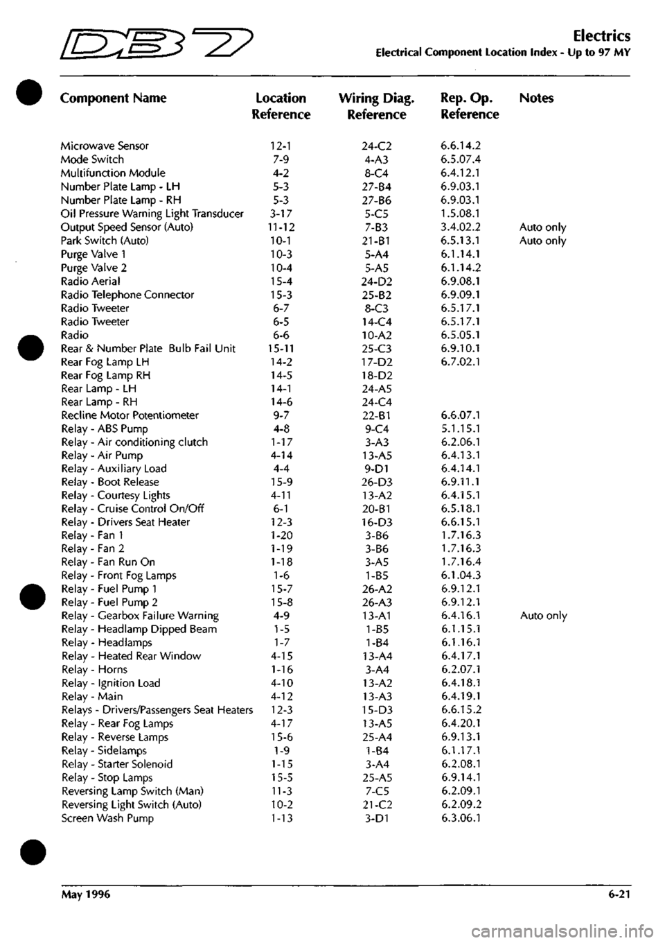
Component Name
Microwave Sensor
Mode Switch
Multifunction Module
Number Plate Lamp - LH
Number Plate Lamp - RH
Oil Pressure Warning Light Transducer
Output Speed Sensor (Auto)
Park Switch (Auto)
Purge Valve 1
Purge Valve 2
Radio Aerial
Radio Telephone Connector
Radio Tweeter
Radio Tweeter
Radio
Rear & Number Plate Bulb Fail Unit
Rear Fog Lamp LH
Rear Fog Lamp RH
Rear Lamp - LH
Rear Lamp - RH
Recline Motor Potentiometer
Relay - ABS Pump
Relay - Air conditioning clutch
Relay - Air Pump
Relay - Auxiliary Load
Relay - Boot Release
Relay - Courtesy Lights
Relay - Cruise Control On/Off
Relay - Drivers Seat Heater
Relay - Fan 1
Relay - Fan 2
Relay - Fan Run On
Relay - Front Fog Lamps
Relay - Fuel Pump 1
Relay - Fuel Pump 2
Relay - Gearbox Failure Warning
Relay - Headlamp Dipped Beam
Relay - Headlamps
Relay - Heated Rear Window
Relay - Horns
Relay - Ignition Load
Relay - Main
)
Location
Reference
12-1
7-9
4-2
5-3
5-3
3-17
11-12
10-1
10-3
10-4
15-4
15-3
6-7
6-5
6-6
15-11
14-2
14-5
14-1
14-6
9-7
4-8
1-17
4-14
4-4
15-9
4-11
6-1
12-3
1-20
1-19
1-18
1-6
15-7
15-8
4-9
1-5
1-7
4-15
1-16
4-10
4-12
Relays - Drivers/Passengers Seat Heaters 12-3
Relay - Rear Fog Lamps
Relay - Reverse Lamps
Relay - Sidelamps
Relay - Starter Solenoid
Relay - Stop Lamps
Reversing Lamp Switch (Man)
Reversing Light Switch (Auto)
Screen Wash Pump
4-17
15-6
1-9
1-15
15-5
11-3
10-2
1-13
Electrics
Electrical Component Location Index - Up to 97 MY
Wiring Diag.
Reference
24-C2
4-A3
8-C4
27-84
27-B6
5-C5
7-B3
21-B1
5-A4
5-A5
24-D2
25-B2
8-C3
14-C4
10-A2
25-C3
17-D2
18-D2
24-A5
24-C4
22-81
9-C4
3-A3
13-A5
9-D1
26-D3
13-A2
20-B1
16-D3
3-B6
3-B6
3-A5
1-B5
26-A2
26-A3
13-A1
1-B5
1-84
13-A4
3-A4
13-A2
13-A3
15-D3
13-A5
25-A4
1-B4
3-A4
25-A5
7-C5
21-C2
3-D1
Rep.
Op. Notes
Reference
6.6.14.2
6.5.07.4
6.4.12.1
6.9.03.1
6.9.03.1
1.5.08.1
3.4.02.2
Auto only
6.5.13.1
Auto only
6.1.14.1
6.1.14.2
6.9.08.1
6.9.09.1
6.5.17.1
6.5.17.1
6.5.05.1
6.9.10.1
6.7.02.1
6.6.07.1
5.1.15.1
6.2.06.1
6.4.13.1
6.4.14.1
6.9.11.1
6.4.15.1
6.5.18.1
6.6.15.1
1.7.16.3
1.7.16.3
1.7.16.4
6.1.04.3
6.9.12.1
6.9.12.1
6.4.16.1
Auto only
6.1.15.1
6.1.16.1
6.4.17.1
6.2.07.1
6.4.18.1
6.4.19.1
6.6.15.2
6.4.20.1
6.9.13.1
6.1.17.1
6.2.08.1
6.9.14.1
6.2.09.1
6.2.09.2
6.3.06.1
May 1996 6-21
Page 53 of 421
Nb 61 62
COLOUR
PIN
BR
1
B
2
}
kKk
B6 CI
BONNET SWITCH
80
RC
es
B
S4
RY 97 Sr
98
YP
NO COLOUH 65
UB
66
U
67
B
68
N
69
UW
t>IN
1 ? 3 4
5
i
-
AREA B6 B3-I3 CI B4-i8 B2-I2
HEADLAMP CONTROL MODULE
NO COLOUR
PIN
63
YO 1
64
YP 2
?
Uiti
C6 CI
NO 70 71
?2
COLOUR
PIN YW YB
YP_.
1 2 3
AREA
C6 C6
V.
.,
SPEED CONTROL
W»
VALVE SPEED CONTROL
PUW
84 N 84-18 85 H eiJi
I BATTERY POST
|
SPL
15
SPL
16
I
i 1 I
rUSEBOX
NO
COLOW
73
R
39
RO
74
N
53
NY
75
UW
34
UW
76
UW
9
UW
77
RS
78
RS
79
RG
80
RC
81
UR
33
UR
82
UR
8
UR
83
WK
6
LG
PIN 1 2 J
4 6 6 7 8
9 10 II 12 13 14 15 16
1/
IS 19 20 21
li
AREA
B3-15
CI
B4-I8
CI
B2-I2
Bl
B2-I2
Bl B6 Dl B6 Dl
B2-I0
61
B2-I0
Bl Be Bl
1 II
^0
D
("
c
D
Q
00=^ Q
D
0
Q
Q
0
Q
Q
QOZ
Q
0
G
G
NO COLOUF 90 GR 14 WU 17 GW 77 RS 83 DM 91 W 92 NR 93 R 61 BR 94 RY 95 U 79 RG 65 UB 87 YR 46 NB 86 BK 4 NP 5 YS
PIN 1 ? 3 4 5 6 7 8 9 10 II 12 13 14 15 16 17
,1?,
,
AREA B4-I6 Bl Bl 03 03 B2-II 83-14 83-15 Al 01 83-13 D3 A2 04 CI 04 Bl Bl
SHEET
8
AREA
Al
.S
^
(•
QQl 0
Gl,
0
G
Qcm
G
0
G
0
G
0
NO COLOUR 96
UW
97
CY
98
YP
70
YW
71
YB
51
RO
15
RO
99
UR
63
YO
50
BR
P»i 1
2 3
4 5 6 7
8 9 10
II 12 1?
AREA 82-12
Dl
01 A3 A3 CI 81
82-10
A2 CI
'LH SIDE REPEATER'
fcRUISE
CONTROL!
CLUTCH
SWITCH
NO COLOUR AREA 88
B Dl
99
{R
E±J1
NO COLOUR AREA 86 BK 86 67 YR B6
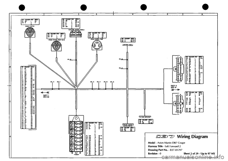
^27 Wiring Diagram
Model
-
Aston Martin
DB7
Coupe
Harness Title
-
Left Forward
2
Drawing Part No.
-
B37-81297
Revision
- 0
Sheet
2 of 29
-
Up to 97 MY
Page 55 of 421
NO COLOUR
PIN
116
NV I
I?
B ?
AREA A6
Si.
H6
COLOUR
fiN
ABEX"
125
N I
B3-23 12?
BY 2 SS_
NO
COLOUR
PIN
100
B I
101
PY ?
AREA B2-20 BI-19
HO
COLOUR
117
B
119
B
120
B
AREA
A2 A2
_«
NO COLOUR
PIN
ASET
103
B I CI
105
Py ' CI
NO COLOUR
PIN
102
B 1
103
B 1
lOfl
PT 2
105
PY 2
Ali^A B2-20
Bl
BI-19
fl
EARTH POINT
COOLANT
LOW
LEVEL SENSOR
AIR
CON
RELAY
l«
SPl
19
SPL
20
HO COLOUR
PIN
135
NS 65
136
UB 86
137
KB 87
87A
138
RH 3?
AREA
C6 C6
C3-22
..»,
.
NO COLOUR
PIH
133
P 85
140
PB 86
141
P 87
87A
14?
PY 30
AREA C4-24 ce C4-24
.BLI9..
NO COLOUR
PIH
115
N 85
143
BC 86
144
WY 87
S7A 110
WR 30
AREA 02 B4 C6
C2
NO COLOUR
PIK
146
RY 85
120
8 86
147 KB
87
129
UR 87A
130 BG
30
ARCA
A6 B2 C3-22 03 03 STARTER SOLENOID RELAY FAN
RUN ON
RELAY
NO COLOUR AREA 121
WR £5_
HO COLOUR 124
NG
146
RY
126
BY
116
NY
PIN 85 86 8/ 87A
55
AREA
A2 A5 A2
A2
NO COLOUR
PIH
123
NY 85
127
UN 86
148
KB 87
87A
lie
HY 30
AREA
B2 D3
C3-22
.^2...
l/
NO COLOUR
PIN
106
B I
W-S&
2_
AREA 82-21 C6 LOW LEVEL SENSOR
NO COLOUR PIN
ARET
I 110
WR 2 «4
STARTER MOTOR SOLENOID
NO COLOUR III
B
112
e
AREA B2-2I 82-20
SCREEN WASH PUMP
NO COLOUR
PIN
lOe
B 1
109
LCB 2
3 4
AR^A B2-2I C6 NO 113 114 l|^
COLOUR N N H
AlttA A2 B3-23
M
BATTERY
POSTL
NO COLOUR
133
B
134
aw
AREA B2-2I
J
RH
SIDE n REPEATER
NO COLOUR
PIN
131
YR I
132
BK 2
AREA ce C6 J CRUISE CONTROL ^ CLUTCH SWITCH
c
D:
r
ID ID
i D)
IDczt
mm
ffl
m
m m
ID Ul
ii=ir
i m
m ID
Trff'TsrawPir
134
OW
144
WY
135
NS
136
UB
138
RN
140
PB
IJI
YR
132
BK
121
WR
145
BC
109
LCB
149
P
107
BS
1 2 3 4 5 6 7 8 9
10
II 12 13 14 15 16 17 18 19
_.29
AREA
C4 A4 A3 A3 A5 A4 C4 C4 62 B4
01
C4-24
CI
NO COLOUR
PIN
127
UN 1
128
KB 2
129
UR 3
130
Bf. 4
AREA
AS
C3-22
A5
«5
SHEET
14
AREA
B4
SHEET
6
AREA
B3
^27
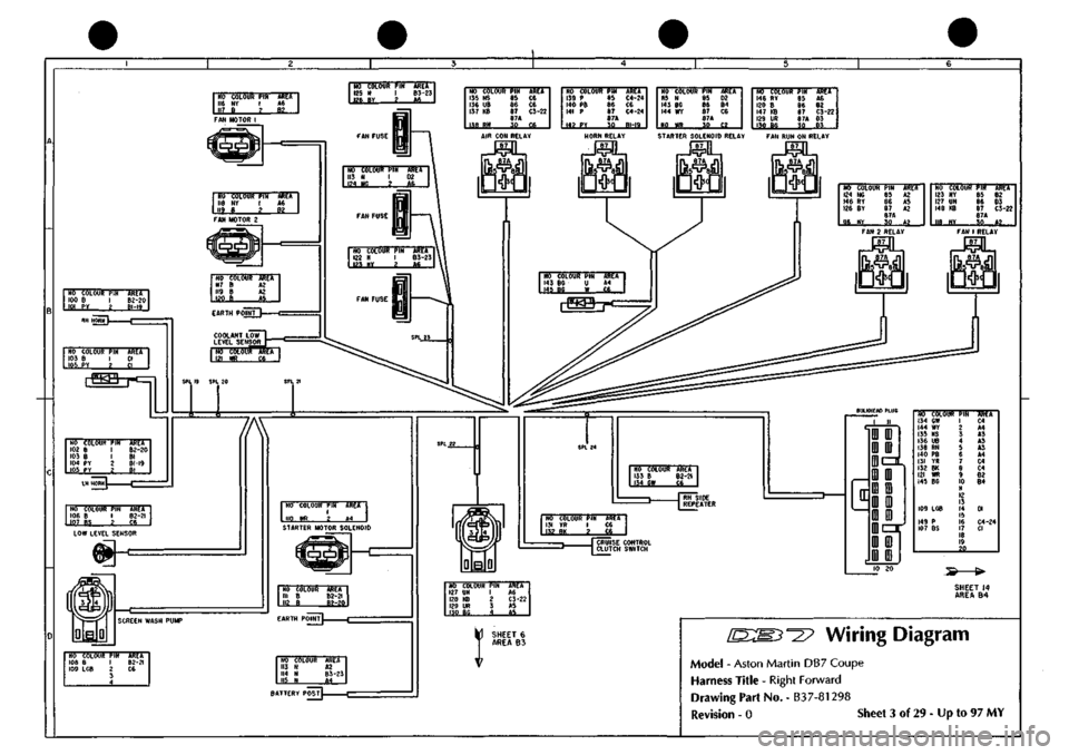
Wiring Diagram
Model
-
Aston Martin DB7 Coupe
Harness
Title
-
Right Forward
Drawing
Part No.
-
B37-81298
Revision
- 0
Siieet
3 of
29
-
Up
to 97 MY
Page 108 of 421
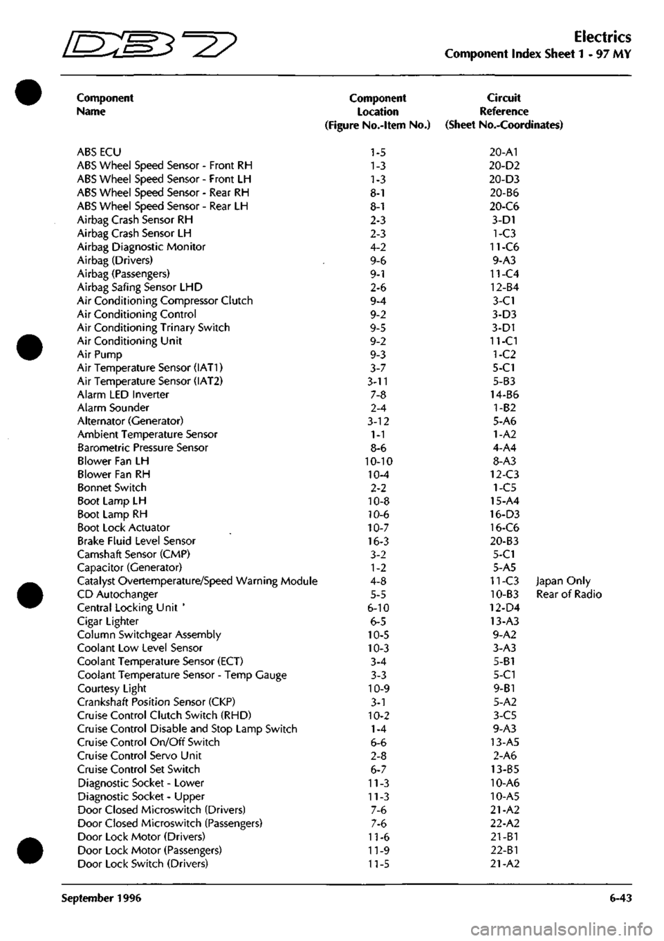
^7
Electrics
Component Index Sheet 1-97 MY
Component
Name
ABS ECU
ABS Wheel Speed Sensor - Front RH
ABS Wheel Speed Sensor - Front LH
ABS Wheel Speed Sensor - Rear RH
ABS Wheel Speed Sensor - Rear LH
Airbag Crash Sensor RH
Airbag Crash Sensor LH
Airbag Diagnostic Monitor
Airbag (Drivers)
Airbag (Passengers)
Airbag Safing Sensor LHD
Air Conditioning Compressor Clutch
Air Conditioning Control
Air Conditioning Trinary Switch
Air Conditioning Unit
Air Pump
Air Temperature Sensor (IAT1)
Air Temperature Sensor (IAT2)
Alarm LED Inverter
Alarm Sounder
Alternator (Generator)
Ambient Temperature Sensor
Barometric Pressure Sensor
Blower Fan LH
Blower Fan RH
Bonnet Switch
Boot Lamp LH
Boot Lamp RH
Boot Lock Actuator
Brake Fluid Level Sensor
Camshaft Sensor (CMP)
Capacitor (Generator)
Catalyst Overtemperature/Speed Warning Module
CD Autochanger
Central Locking Unit '
Cigar Lighter
Column Switchgear Assembly
Coolant Low Level Sensor
Coolant Temperature Sensor (ECT)
Coolant Temperature Sensor - Temp Gauge
Courtesy Light
Crankshaft Position Sensor (CKP)
Cruise Control Clutch Switch (RHD)
Cruise Control Disable and Stop Lamp Switch
Cruise Control On/Off Switch
Cruise Control Servo Unit
Cruise Control Set Switch
Diagnostic Socket - Lower
Diagnostic Socket - Upper
Door Closed Microswitch (Drivers)
Door Closed Microswitch (Passengers)
Door Lock Motor (Drivers)
Door Lock Motor (Passengers)
Door Lock Switch (Drivers)
Component
Location
(Figure No.-ltem No.)
1-5
1-3
1-3
8-1
8-1
2-3
2-3
4-2
9-6
9-1
2-6
9-4
9-2
9-5
9-2
9-3
3-7
3-11
7-8
2-4
3-12
1-1
8-6
10-10
10-4
2-2
10-8
10-6
10-7
16-3
3-2
1-2
4-8
5-5
6-10
6-5
10-5
10-3
3-4
3-3
10-9
3-1
10-2
1-4
6-6
2-8
6-7
11-3
11-3
7-6
7-6
11-6
11-9
11-5
Circuit
Reference
(Sheet No.-Coordinates)
20-A1
20-D2
20-D3
20-B6
20-C6
3-D1
1-C3
11-C6
9-A3
11-C4
12-B4
3-C1
3-D3
3-D1
11-CI
1-C2
5-C1
5-B3
14-B6
1-B2
5-A6
1-A2
4-A4
8-A3
12-C3
1-C5
15-A4
16-D3
16-C6
20-B3
5-C1
5-A5
11-C3 Japan Only
10-B3 Rear of Radio
12-D4
13-A3
9-A2
3-A3
5-B1
5-C1
9-B1
5-A2
3-C5
9-A3
13-A5
2-A6
13-B5
10-A6
10-A5
21-A2
22-A2
21-B1
22-Bl
21-A2
September 1996 6-43
Page 110 of 421
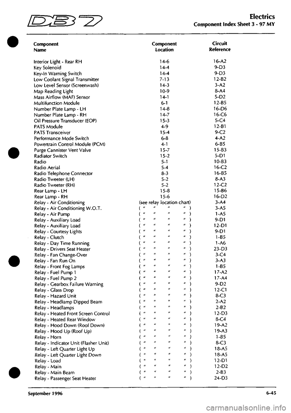
Electrics
Component Index Sheet 3 - 97
MY
Component
Name
Interior Light - Rear RH
Key Solenoid
Key-In Warning Switch
Low Coolant Signal Transmitter
Low Level Sensor (Screenwash)
Map Reading Light
Mass Airflow (MAF) Sensor
Multifunction Module
Number Plate Lamp - LH
Number Plate Lamp - RH
Oil Pressure Transducer (EOP)
PATS Module
PATS Transceiver
Performance Mode Switch
Powertrain Control Module (PCM)
Purge Cannister Vent Valve
Radiator Switch
Radio
Radio Aerial
Radio Telephone Connector
Radio Tweeter (LH)
Radio Tweeter (RH)
Rear Lamp - LH
Rear Lamp - RH
Relay - Air Conditioning
Relay - Air Conditioning W.O.T.
Relay - Air Pump
Relay - Auxiliary Load (
Relay - Auxiliary Load (
Relay - Courtesy Lights (
Relay - Clutch (
Relay-Day Time Running (
Relay - Drivers Seat Heater (
Relay - Fan Change-Over (
Relay - Fan Run On
Relay - Front Fog Lamps
Relay - Fuel Pump 1
Relay - Fuel Pump 2
Relay - Gearbox Failure Warning
Relay - Glass Drop
Relay - Hazard Unit
Relay - Headlamp Dipped Beam
Relay- Headlamps
Relay - Heated Front Screen Control
Relay - Heated Rear Window
Relay - Hood Down (Roof Down)
Relay - Hood Up (Roof Up)
Relay - Horn
Relay - indicator Unit (Flasher Unit)
Relay - Left Quarter Light Up
Relay - Left Quarter Light Down
Relay - Load
Relay- Main
Relay - Main Beam
Relay - Passenger Seat Heater
Component
Location
14-6
14-4
14-4
7-13
14-3
10-9
14-1
6-1
14-8
14-7
15-3
4-9
15-4
6-8
4-1
15-7
15-2
5-1
5-4
8-3
5-2
5-2
15-8
15-6
see relay location chart) di II II II
II II II II
II II II II
11 II II II
II II II II
II II II II
II II II II
II II II II
II II II II
11 II II II
II II II II
II II II II
II II It II
II II II II
11 II II II
II II II II
II II II II
II II II II
II II II II
II It II II
II II II II
11 II II II
II II II II
11 II II II
11 II II II
II II II II
II II II II
II II II II
II II II II
II II II II
Circuit
Reference
16-A2
9-D3
9-D3
12-82
3-A2
8-A4
5-D2
12-B5
16-D6
16-C6
5-C4
12-B1
9-C2
4-A2
6-B5
15-B3
5-D1
10-B3
16-C2
16-B5
8-A3
12-C2
15-B6
16-D2
3-A4
3-A5
1-A5
9-D1
12-D1
9-D1
1-B5
1-A6
23-D3
3-C4
3-A3
) 1-B5
) 17-A2
) 17-A4
9-D2
) 12-C1
) 8-C3
2-A2
) 2-B2
) 12-D3
) 8-C4
) 19-A2
) 19-A3
) 1-85
) 8-C3
) 18-A5
) 18-A5
) 12-D1
) 12-D2
) 2-83
) 24-D3
September 1996 6-45
Page 129 of 421
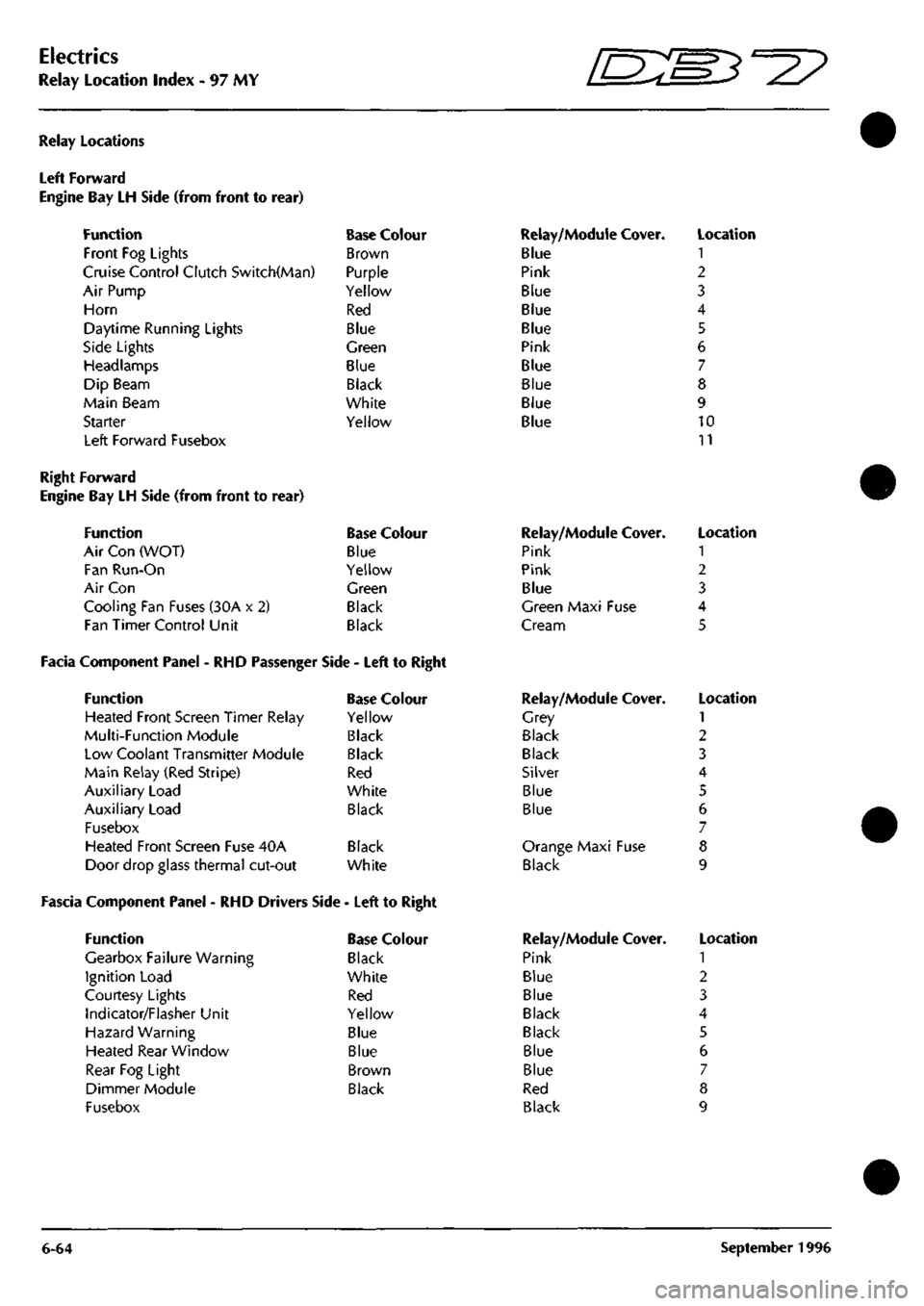
Electrics
Relay Location Index - 97 MY 5^^?
Relay Locations
Left Forward
Engine Bay LH Side (from front to
Function
Front Fog Lights
rear)
Cruise Control Clutch Switch(Man)
Air Pump
Horn
Daytime Running Lights
Side Lights
Headlamps
Dip Beam
Main Beam
Starter
Left Forward Fusebox
Base Colour
Brown
Purple
Yellow
Red
Blue
Green
Blue
Black
White
Yellow
Relay/Module Cover.
Blue
Pink
Blue
Blue
Blue
Pink
Blue
Blue
Blue
Blue
Location
1
2
3
4
5
6
7
8
9
10
11
Right Forward
Engine Bay LH Side (from front to rear)
Function Base Colour
Air Con (WOT) Blue
Fan Run-On Yellow
Air Con Green
Cooling Fan Fuses (30A x 2) Black
Fan Timer Control Unit Black
Facia Component Panel - RHD Passenger Side - Left to Right
Function Base Colour
Heated Front Screen Timer Relay Yellow
Multi-Function Module Black
Low Coolant Transmitter Module Black
Main Relay (Red Stripe) Red
Auxiliary Load White
Auxiliary Load Black
Fusebox
Heated Front Screen Fuse 40A Black
Door drop glass thermal cut-out White
Fascia Component Panel - RHD Drivers Side - Left to Right
Function
Gearbox Failure Warning
Ignition Load
Courtesy Lights
Indicator/Flasher Unit
Hazard Warning
Heated Rear Window
Rear Fog Light
Dimmer Module
Fusebox
Base Colour
Black
White
Red
Yellow
Blue
Blue
Brown
Black
Relay/Module
Pink
Pink
Blue
Cover.
Green Maxi Fuse
Cream
Relay/Module
Grey
Black
Black
Silver
Blue
Blue
Cover.
Orange Maxi Fuse
Black
Relay/Module
Pink
Blue
Blue
Black
Black
Blue
Blue
Red
Black
Cover.
Location
1
2
3
4
5
Location
1
2
3
4
5
6
7
8
9
Location
1
2
3
4
5
6
7
8
9
6-64 September 1996
Page 136 of 421
NO 66 67 68 61 6I>
COLOUR
NR NU R RU NR
PIN RS 86 87 8« 30
AREA 2.B6
2.B3-I6
2.B4-I9
2.C2 2.D3
NO 75 76 77
74
COLOUR
B U UR
N
PIN 85 86
87 87A
30
AREA
1.03-8
2.82-11
2.B2-I0
2.B4-22
NO 83 M 85
82
COLOUR
8G wr WR
N
PIN B5 86
87 B7A
30
AREA 2.B3 2.86 2.A5
2.84-20
SIDELIGHT RELAY I
87
{GREEN BASE
JqpL L 87A
DW|
OlP BEAM RELAY I 87 I BLACK BASE
87A
'5^BI
lO
SHEET I AREA C6 <4 «
mu
STARTER RELAY I
87 I
YELLOW BASE
87A
'5^ei
NO COLOUR
PIN
I
.
85
WD 2
AREA
2.A3
NO 71 7? 73
70
COLOUR
N8 WG WU
WG
pm 85 86 8/ 87A 30
AREA 2.C6
2.82-9
2.B3-I5
2.B2-9
HEADLAMP RELAY
I
87
I
BLUE BASE
BTA
DW|
NO COLOUR 121
Y
122
WY
123
YU
124
U
125
BP
126
LGY
127
YR
30
B
PIN
1 7
3 4 5 6
7 8
9 10
AREA 2.D6
2.C6 2.C6 2.C6 2.C6
2.B3-I4
2.C6 l,D2
NO 79 80 81
78
COLOUR
B UW UW
N
PIN 85 86
87 87A
30
AREA LC3-e 2.B6
2.82-13
2.84-21
MAIN BEAM RELAY
I 87 I WHITE BASE
87A
SPL 14 SPL 15
HO 118 119 120
COLOUR N N N
AREI 2.84 ?.B4 2.84
20 21 22
iSTARTER MOTOR I
•BATTERY POSTi
^
NO 83 86
COLOUR PIN 8G U BG W
AREA 2.A3 2.D6
SPL 22 SPL 24
xf
3 C
'-Fw^'
NO 69 87
COLOUR
PIN
WN
U
WU
W
AREA
2.C2-I2
2.82-11
^
'-Fag—'
NO COLOUF 105 N 53 NG 106 N 57 P 108 WP 109 LGY 110 WP 12 WU III N 112 NU 113 N 2 NP
PIN 23 24 25 26 27 28 29 30 31 32 33 34 35 36 37 38 39 40 41 42 43 44
AREA
2.84-21
I.A5
2.84-20
I.B5
2.83-18
2.83-14
2.B3-I8
I.A2
2.84-21
2.B3-I6
2.84-20
1.83
2^n2^.
25nFI3;^6
'^'^^
3lnfl6n32
3^EI7j^.
35nFI8n3e
3^n9^,
,^r2^,
3^.2^
5^F3^6
7^E4^
9^E5^0
1^6^
,3^E7^4
l5j^E8^6
I^P9^8
i9nFiOn20|
2^r,l^2
NO 88 89
COLOUR
PIN
WU
U
WU
W
AREA
2.B3-I5
2.B2-I1
NO COLOUf 90
WP
91
WN
92
N
45
NY
93
N
65
NR
94
WP
95
WG
96
UW
33
UW
97
UW
7
UW
98
RG
99
RS
100
RG
101
RG
102
UR
32
UR
103
UR
6
UR
PIN 1 2 3 4 5 6 7 8 9 10 II 12 13 14 15 16 17 18 19
20 21 22
AREA
2.B3-I8
2.C2-I2
2.B4-2I
I.A4
2.84-22
2.AI
2.83-18
2.82-9
2.83-13
1.02
2.83-13
I.A2
2.B3-I7
I.C2-5
2.83-17
LBI-I
2.B2-IO
1.02
2.82-10
I.A2
iCRUISE CONTROLi
("
D D • D
DDC^
G D D D D D D D DQzr D • D 0
NO COLOUF 128 GR 49 GP 16 GW
84 WY 66 NR 129 R 44 8R 130 RY 131 U
80 UW 52 GP 71 NB 114 8K 133 WP 3 YS
PIN
1 2 3 4 5 6 7 8 9 10 II 12 13 14 15 16 17 18
AREA
2.B4-24
I.B4 I.AI
2.A3 2.AI
2.B4-I9
I.C5
I.C2-6
2.B3-I5
2.B2 1.84 2.B2 2.04
2.83-18
1.83
SHEET 8 AREA Al
-(*•
LH SIDE REPEATER
I
I CRUISE CONTROL] CLUTCH SWITCH
NO COLOUR AREA
116 B
I.C3-8
117
GR
2.84-24
NO 114 115
COLOUR AREA 8K
2.C6
YR 2.B4-23
c
1
12 D 0 0 G D D D[E±
HDD
^ • n Qtrr 0 G D D D D
NO COLOUf 134
UW
54
G
55
KB
122
WY
124
U
127
YR
47
RO
13
RO
135
GY
123
YU
1
LG
136
LGY
137
NU
58
PB
138
YR
125
BP
121
Y
139
WU
86
BG
PIN 1 ? 3 4 5 6 7 8 9 10 II 12 13 14
15 16
17 IB 19 20
AREA
2,B3-I3
I.A5 I.A5 2.A6 2.A6 2.Ae
LB4
I.A2
I.C2-7
2.A6 1.83
2.B3-I4
2.83-16
1.85
2.84-23
2.A6 2.A6
2.83-15
2.83
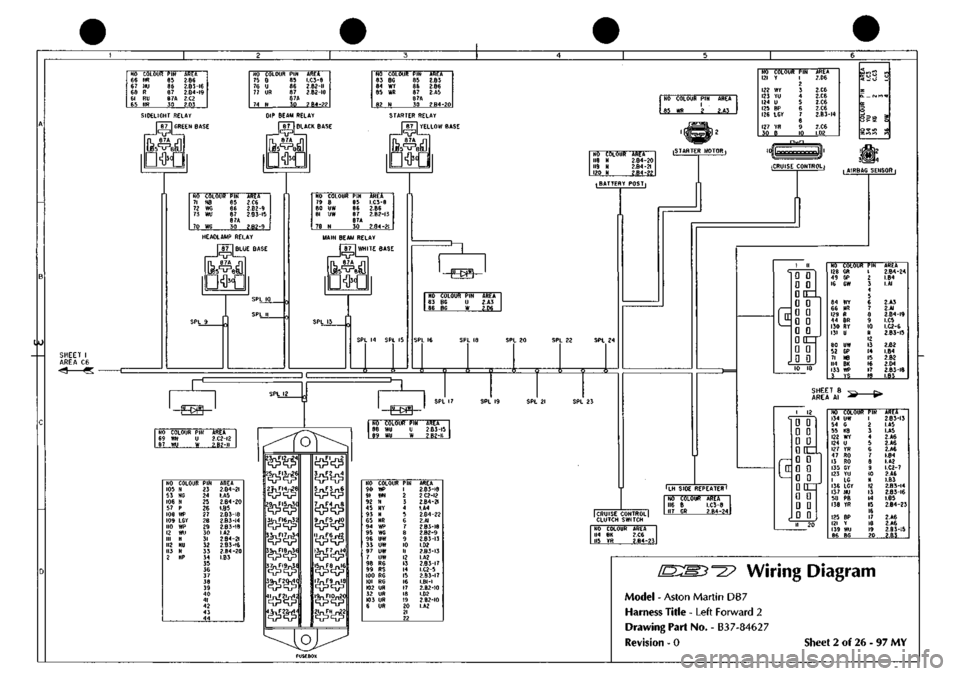
'^^? Wiring Diagram
Model - Aston Martin DB7
Harness Title - Left Forward 2
Drawing Part No. - B3
7-8462
7
Revision - 0 Sheet 2 of 26 - 97 MY
Page 279 of 421
Air Conditioning
Contents '=2?
System Fault Diagnosis
Fault Finding
Blower Motor Test
Open Water Temperature Switch Needs
Short Water Temperature Switch Leads
Refrigeration
Compressors
Compressor Clutch Control
Trinary Switch
Condenser
Receiver-Drier
Evaporator
Expansion Valve
Sanden Compressor SD7H15
Manifold Gauge Set
System Checking with the Manifold Gauge Set
Evacuating the Manifold Gauge Set
Connecting the Manifold Gauge Set
Stabilising the System
Purging the Test Hoses
Leak Test
Manifold Gauge Set Check Procedures
Refrigerant Slightly Low.
Refrigerant Excessively Low.
Air In The System.
Compressor Malfunction
Moisture in the System
A Large Amount of Air in the System.
Expansion Valve Malfunction.
Expansion Valve Malfunction
Restriction in the High Pressure Side.
Torque Levels for the Hose Connections
8-30
8-33
8-33
8-33
8-34
8-35
8-35
8-35
8-35
8-36
8-36
8-36
8-37
8-39
8-39
8-39
8-39
8-40
8-40
8-41
8-41
8-42
8-42
8-43
8-44
8-45
8-45
8-46
8-46
8-47
Air Conditioning Procedures
Depressurising
Recovering Refrigerant
Evacuating and Recycling the Refrigerant
Recharging the System
Compressor Oil Check
8-47
8-47
8-48
8-49
8-49
8-2 May 1996
Page 288 of 421
^7
Air Conditioning
Temperature Distribution System
Air Conditioning Function Switch
When AC, DEM or Re-circulation ^v is selected the system engages the Air conditioning compressor using the
electromagnetic clutch. The in-car temperature is automatically corrected to the pre selected level by the system
sensors.
When MAN (manual mode) is selected it provides the operator selection of fan speed and in-car temperature
selection facilities. The in-car temperature is not thermostatically corrected to a predetermined level by the system
sensors.
When ECO is selected the system is in economy mode which allows the fan speed and heating levels to be selected
but gives no cooling. The air conditioning compressor is not engaged putting a minimum load on the engine.
When manual re-circulation is selected the blower flaps are closed and only that air which is in the vehicle is re
circulated.
When the ignition is turned off the blower flaps revert to the fresh air position.
Refrigeration Cycle
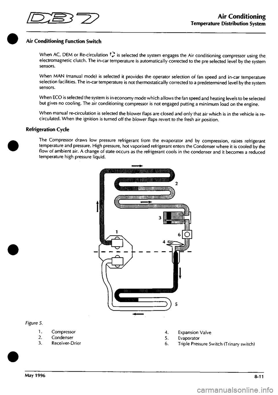
The Compressor draws low pressure refrigerant from the evaporator and by compression, raises refrigerant
temperature and pressure. High pressure, hot vaporised refrigerant enters the Condenser where it is cooled by the
flow of ambient air. A change of state occurs as the refrigerant cools in the condenser and it becomes a reduced
temperature high pressure liquid.
Figure 5.
1.
2.
3.
Compressor
Condenser
Receiver-Drier
4.
Expansion Valve
5. Evaporator
6. Triple Pressure Switch (Trinary switch)
May 1996 8-11