wheel torque ASTON MARTIN DB7 1997 Workshop Manual
[x] Cancel search | Manufacturer: ASTON MARTIN, Model Year: 1997, Model line: DB7, Model: ASTON MARTIN DB7 1997Pages: 421, PDF Size: 9.31 MB
Page 3 of 421

^?
Introduction
#
••t
*<;'..
Introduction '-^;^'^<-~'
^--"^^zfjj^^T^""
Workshop Manual Sections
The
DB7
Workshop Manual
is
divided .jnto,9seGtipnsE.a&foli
1 Engine
2.
Fuel,
Emission Control
and
Exhaust
3. Transmission
4.
Suspension
and
Steering
5. Brakes, Wheels
and
Tyres
6. Electrics
7. Chassis
and
Body
8.
Air
Conditioning
9. Aston Martin Diagnostic System
Procedure Numbering
The workshop manual procedures
are
numbered using
the
parts list numbers
as a key. The
first
two
digits
oi a
workshop manual procedure number
are
also
the
parts list number
(e.g.
1.5.01
Sump Removal relates
to PL 1.5 Oil
Pump
and
Sump). Thus when carrying
out a
procedure,
you can
quickly locate
the
relevant parts illustration
and
spare parts list.
To avoid excessive repetition, each procedure will
be
fully detailed once
in its
appropriate place
in the
manual.
In
any other location where this procedure
is
required,
it
will
be
referenced only
by its
title
and its
procedure number.
Special Tools
Where special service tools
are
required
to
perform
an
operation,
the
tool number
is
recorded
at the
point
of use
within
the
procedure.
An
index
and
illustrated list
is
provided
in
this section
for the
purpose
of
identifying special
tools.
References
References
to the
left, right, front
or
rear
of
the vehicle
or of
a component
are
always made as
if
sitting
in the
drivers
seat facing forward.
Any
such references
to
assemblies removed from
the
vehicle
are to the
normal orientation
of
the assembly when fitted
in the
vehicle.
Repairs
and
Replacements
Where replacement parts
are
required,
it is
essential that only genuine Aston Martin parts
are
used. Your attention
is drawn
to the
following points concerning repairs
and the
fitting
of
genuine Aston Martin parts
and
accessories:
• Safety features embodied
in the
vehicle
may be
impaired
if
other than genuine Aston Martin parts
are
fitted.
In certain territories, legislation prohibits
the
fitting
of
parts which
are not
produced
to the
manufacturers
specification.
• Adhere
to
torque wrench settings given
in
this manual.
• Locking devices, where specified, must
be
fitted.
If the
efficiency
of a
locking device
is
impaired during
removal,
it
must
be
renewed.
•
The
vehicle warranty
may be
invalidated
by the
fitting
of
other than genuine Aston Martin parts.
April
1997 Hi
Page 391 of 421

The Aston Martin Lagonda Diagnostic System
Users Guide ^=2?
Transmission Diagnostics
Automatic transmission DB7s are fitted with a GM4L80-
E gearbox electronically controlled by a Transmission
Control Unit (TCM)
The TCM is mounted on the rear left wheel
arch.
It may be
electronically accessed from the upper diagnostic socket.
The TCM continuously monitors requests made by the
driver via the gear selector, throttle pedal, mode switch,
etc. This data is used in conjunction with speed input from
the transmission unit to calculate the optimum shift points
undercurrentconditions.Shiftpressureand ignition retard
are also controlled from this data to enhance shift quality
and reduce transmission wear.
TheTCM also detects faults within the transmission system
and stores the relevant fault codes for later analysis.
Gearshifts are controlled by two solenoid valves and a
pressure regulator within the transmission valve block
assembly.
If a serious fault occurs, the TCM removes all electrical
power from these valves and the transmission defaults to
a 'limp home' condition. In this state, only mechanical
selection of either reverse or second gear is available.
Gearshift Timing
Inputs from the performance mode switch (Sport, Normal
or 1st Gear Inhibit) and the throttle position sensor are
used to modify transmission gearshift operation
as
required
by the driver.
Sport mode raises the roadspeed at which gearshifts occur
enabling higher acceleration rates for the vehicle.
1st gear inhibit prevents engagement of first gear to reduce
the risk of wheel slip in icy conditions.
The throttle position sensor signal is continuously
monitored by the TCM to detect a rapid throttle opening.
If the throttle position sensor signal rises rapidly to above
4.5 volts, a 'Kickdown' condition is initiated. In this
condition,
upshifts are delayed to higher road speeds to
provide the higher acceleration required for overtaking
etc.
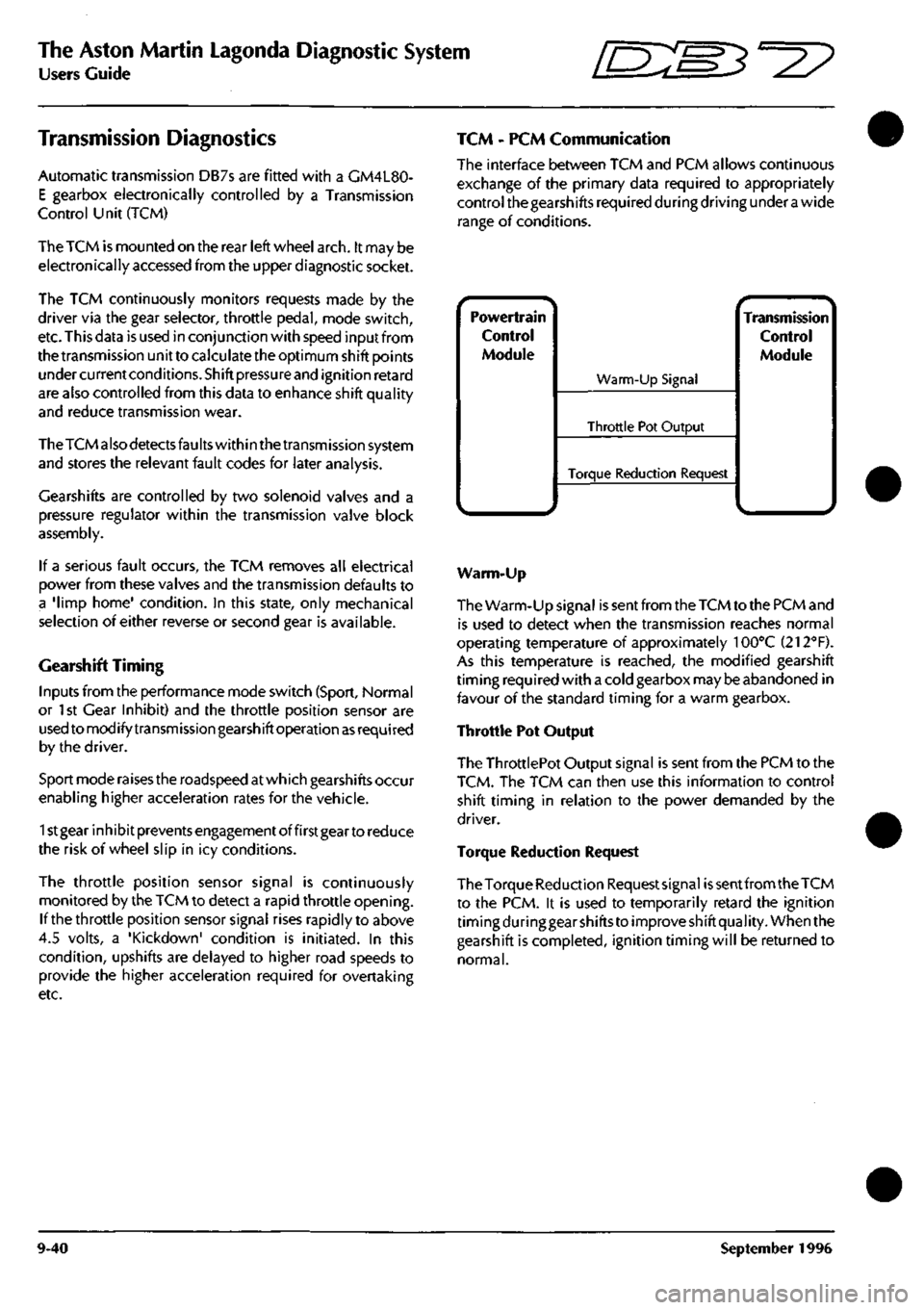
TCM - PCM Communication
The interface between TCM and PCM allows continuous
exchange of the primary data required to appropriately
control the gearshifts required during driving under
a
wide
range of conditions.
Powertrain
Control
Module
^.. ^
Warm-Up Signal
Throttle Pot Output
Torque Reduction Request
^ •- -^ Transmission
Control
Module
Warm-Up
The Warm-Up signal is sent from the TCM to the PCM and
is used to detect when the transmission reaches normal
operating temperature of approximately 100°C (212"'F).
As this temperature is reached, the modified gearshift
timing required with a cold gearbox may be abandoned in
favour of the standard timing for a warm gearbox.
Throttle Pot Output
The ThrottlePot Output signal is sent from the PCM to the
TCM.
The TCM can then use this information to control
shift timing in relation to the power demanded by the
driver.
Torque Reduction Request
The Torque Reduction Requestsignai
is
sent from the TCM
to the PCM. it is used to temporarily retard the ignition
timing during gear shifts to improve shift quality. When the
gearshift is completed, ignition timing will be returned to
normal.
9-40 September 1996
Page 393 of 421

The Aston Martin Lagonda Diagnostic System
Users Guide ^7
TCCS Torque Convertor Clutch Solenoid
The torque converter clutch solenoid is mounted on the
valve body. The signal is Pulse Width Modulated at 32Hz
to provide closed loop control of the pressure across the
converter clutch plates. 1 bit = 0.39% Range 0 to 100%
TP Throttle Position
This is provided by the EECV Engine Management System
as a Pulse Width Modulated signal derived from the
throttle position signal read by that module from the
throttle position sensor.
TCS Torque Convertor Slip
Torque converter slip is defined
as
the difference between
the Input/turbine (ni) speed and the Engine speed (Ne):
Slip = Ne-Ni. The PWM duty cycle may increase from 0
to 100% when TCC is fully applied. In practice a 100%
duty cycle will be achieved only if
a
large slip is detected.
Normal ly only a 50 to 95% duty cycle will be required for
full application of the TCC. Slip is expressed in rpm. 1 Bit
- 1/8 rpm. Range -4096 to +4096 rpm.
TCSW Transmission Control Switch
A three position switch allows the driver to select Sport,
Normal or 1st Gear Inhibit mode. When 'Sport' is selected
gearshifts take place at higher engine revs. When '1st
Gear Inhibit' is selected, the transmission only operates in
the higher forward ratios to prevent wheel slip in icy
conditions.
TISSA Turbine Input Shaft Speed
Turbine speed is the speed of the input shaft of the
transmission measured by the input speed sensor mounted
on the transmission. An alternating waveform is induced
in the sensor by 31 serrations on the forward clutch
housing as it rotates. The waveform frequency and
amplitude is low at low speeds and high at high speeds.
The TCM changes this signal into a digital signal. 1 bit =
1/8 RPM. Range: 0 - 8192 RPM.
TOS+ Transmission Output Speed
The output speed sensor is mounted on the transmission
case and measures the speed of the output shaft. As the
shaft rotates an alternating waveform is induced in the
sensor which varies in frequency and voltage. The wave
form is converted into
a
digital signal by the TCM and used
to control TCC, line pressure, shift timing and torque
management. 1 bit = 1/8 RPM. Range 0-8192 RPM
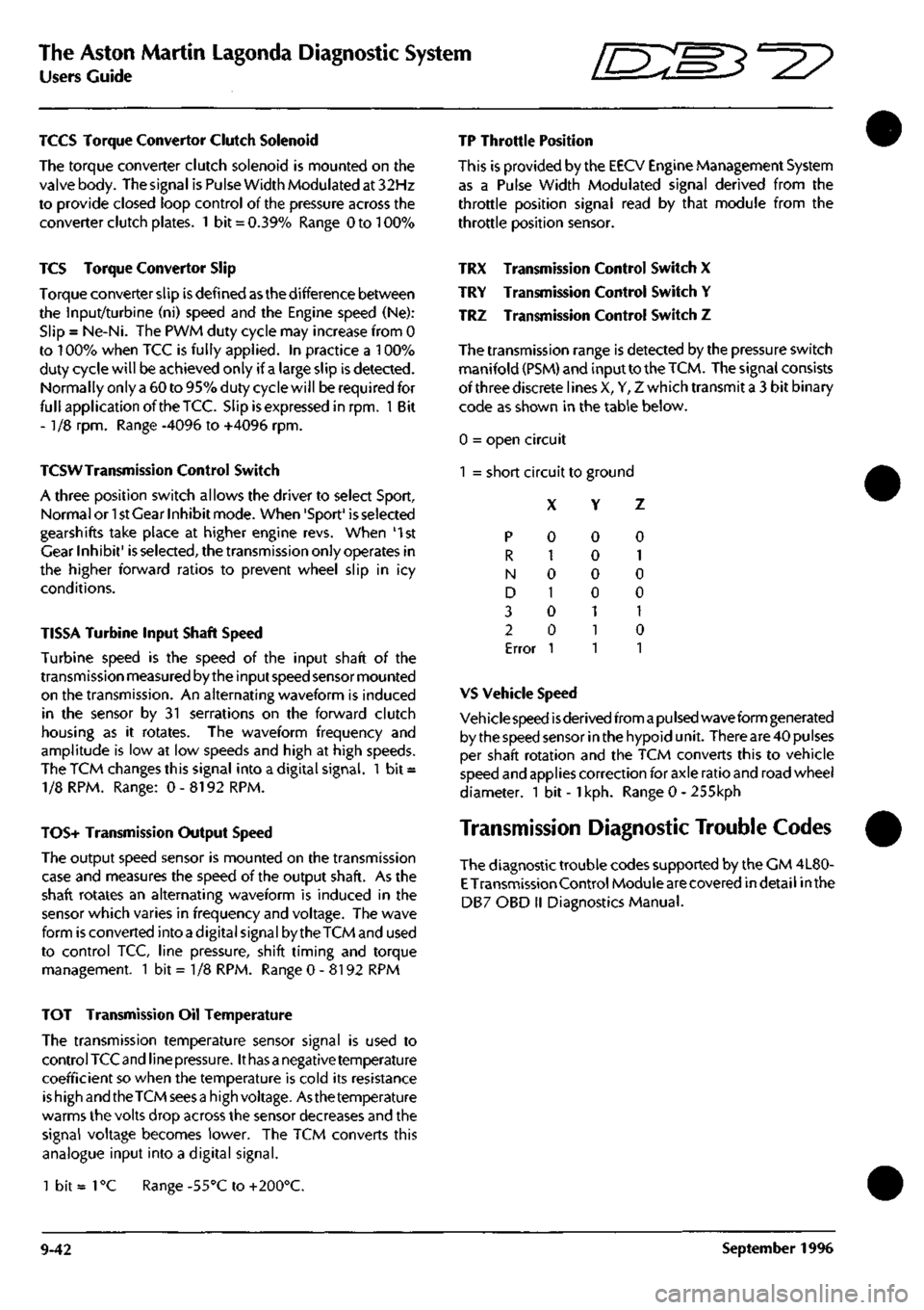
TRX Transmission Control Switch X
TRY Transmission Control Switch Y
TRZ Transmission Control Switch Z
The transmission range is detected by the pressure switch
manifold (PSM) and input to the
TCM.
The signal consists
of three discrete lines X, Y, Z which transmit a 3 bit binary
code as shown in the table below.
0 = open circuit
1 = short circuit to ground
X Y Z
p
R
N
D
3
2
Error
0
1
0
1
0
0
1
0
0
0
0
1
1
1
0
1
0
0
1
0
1
VS Vehicle Speed
Veh icie speed
is
derived from
a pu Ised
wave form generated
by the speed sensor in the hypoid unit. There are 40 pulses
per shaft rotation and the TCM converts this to vehicle
speed and applies correction for axle ratio and road wheel
diameter. 1 bit -
1
kph. Range 0 - 255kph
Transmission Diagnostic Trouble Codes
The diagnostic trouble codes supported by the CM 4L80-
E
Transmission Control Module are covered indetail inthe
DB7 OBD II Diagnostics Manual.
TOT Transmission Oil Temperature
The transmission temperature sensor signal is used to
control TCC and line
pressure.
It
has a
negative temperature
coefficient so when the temperature is cold its resistance
is high and the TCM sees
a
high voltage. Asthe temperature
warms the volts drop across the sensor decreases and the
signal voltage becomes lower. The TCM converts this
analogue input into a digital signal.
1 bit =
1
°C Range -55°C to +200°C.
9-42 September 1996