maintenance ASTON MARTIN DB7 1997 Workshop Manual
[x] Cancel search | Manufacturer: ASTON MARTIN, Model Year: 1997, Model line: DB7, Model: ASTON MARTIN DB7 1997Pages: 421, PDF Size: 9.31 MB
Page 278 of 421
in:!M3^^?
Air Conditioning
Contents
Contents
General Description 8-5
Specifications 8-5
Climate Control System 8-6
System Description 8-7
Special Servicing Tools and Equipment 8-7
Working Practices 8-8
General 8-8
Handling Refrigerant 8-8
Handling Lubricating Oil 8-8
System Maintenance 8-8
Temperature Distribution System 8-9
Fan Speed Control (Mode Switch) 8-10
Face Level Temperature Differential 8-10
Temperature Rotary Control 8-10
Refrigeration Cycle 8-11
System Protection 8-12
General System Procedures 8-12
Leak Test 8-12
Charge Recovery (System Depressurisation) 8-12
Evacuating the System 8-13
Adding Compressor Lubricating Oil 8-13
Adding Refrigerant 8-14
Functional Check 8-15
System Trouble Shooting 8-1 7
Electronic Control Module (ECM) 8-19
In Car Controls 8-21
Temperature Demand Switch 8-21
Face Level Differential Controller 8-21
Air Conditioning Function Switch 8-22
Fan Speed Control Switch (Mode Switch) 8-23
Temperature Sensors 8-23
Evaporator Sensor 8-24
Motorised In-Car Aspirated Sensor 8-24
Water Temperature Switch 8-25
Blower Motors 8-25
Potentiometers 8-26
Servo Motors 8-27
Vacuum System 8-28
Pressure-Temperature Graphs 8-29
May 1996 8-1
Page 285 of 421
Air Conditioning
Working Practices O" 15-^?
Working Practices
General
Be aware of, and comply
with,
all health and safety
requirements.
Before beginning any repair or service procedure,
disconnect the vehicle battery ground connection
and protect the vehicle from dirt or damage.
Work in a well ventilated, clean and tidy area.
Recovery and chargeequipment must comply
with,
or exceed the standard detailed in the General
Description.
Handling Refrigerant
Wear eye protection at all times.
Use gloves, keep skin that may come into contact
with refrigerant covered. If the refrigerant comes
into contactwith youreyesorskin wash the affected
area immediatelyw'ith cool water and seek medical
advice, do not attempt to treat yourself.
Avoid inhaling refrigerant vapour, it wil
your respiratory system.
irritate
Never use high pressure compressed air to flush out
a system. Under certain circumstances a
combination of HFC 134A and compressed air in
the presenceofa source ofcombustion (for instance,
welding or brazing equipment), results in an
explosion that releases toxic compounds into the
atmosphere.
The refrigerant and CFC 12 must never come into
contact with each other
as
they form an inseparable
mixture that can only be disposed of by incineration.
Do not vent refrigerant directly into the atmosphere,
always use approved recovery equipment.
Refrigerant is costly but it can be recycled. Clean
the refrigerant, using the recovery equipment and
reuse it.
Carry out LeakTestsonly with an electronic analyser
dedicated to Refrigerant El 34A.
Do not attemptto guess the amount of refrigerant in
a system, always recover it and recharge with the
correct charge weight. Do not depress the charge or
discharge port valves to check for the presence of
refrigerant.
Handling Lubricating Oil
Avoid breathinglubricantmist,itwillcauseirritation
to your respiratory system.
Always decant fresh oil from a sealed container. Do
not leave oil exposed to the atmosphere for any
reason other than to fill or empty a system; PAG oil
is hygroscopic (it absorbs water) and iscontaminated
rapidly by atmospheric moisture.
Following the recovery cycle do not reuse the oil
when it has been separated from the refrigerant;
dispose of the oil safely.
System Maintenance
Do not leave the system open to the atmosphere. If
a unit or part of the system is left open for more than
five minutes, it is advisable to renew the receiver-
dryer. There is not a safe period in which work is to
be carried out. Always plug pipes and units
immediately after disconnection and only remove
plugs when re-connecting.
If replacement parts are supplied without transit
plugs and seals do not use the parts. Return them to
your supplier.
Diagnostic equipment for pressure, mass and
volumeshouidbecalibrated regularly and certified
by a third party organisation.
Use extreme care when handling and securing
aluminium fittings, always use a backing spanner
and take special care when handlingtheevaporator.
Use only the correct or recommended tools for the
job and apply the manufacturer's torque
specifications.
Keep the working area, all components and tools
clean.
8-8 May 1996
Page 352 of 421
^?
The Aston Martin Lagonda Diagnostic System
Contents
Installation Instructions
Introduaion 9-2
The Aston Martin Diagnostic System 9-2
Diagnostic System Cables 9-5
Base Station Installation 9-8
Problem Solving 9-16
Service Centres 9-21
Service and Maintenance 9-22
Technical Specifications 9-24
Operating Instructions
The Aston Martin Lagonda Diagnostic System 9-27
Software 9-29
Cable Setup 9-31
Diagnostic Sockets - 97 MY 9-31
Establishing Communications 9-32
System Menu Selections 9-32
PDU Use 9-32
Engine Diagnostics - 97 MY 9-33
Transmission Diagnostics 9-40
Climate Control Diagnostics 9-43
Anti-Lock Brakes Diagnostics 9-43
Passive Anti-Theft (PATS) Diagnostics 9-44
Airbag System Diagnostics 9-45
Seat Belt Pretensioner Diagnostics 9-47
Print Facility 9-49
Digital Multimeter 9-50
Diagnostic Trouble Codes 9-53
Datalogger 9-55
Datalogger Example 9-63
Training 9-66
OBD II Scan Tool 9-66
System Self Test 9-69
The Asterisk (*) Menu 9-69
System Setup 9-70
May 1996 9-1
Page 353 of 421
The Aston Martin Lagonda Diagnostic System
Installation Instructions E:MB^^?
Introduction The Aston Martin Diagnostic System
This guide contains instructions for the installation
of the Portable Diagnostic Unit hardware in Aston
Martin Dealer workshops. To achieve maxinnum
benefit from the system, please follow the
instructions carefully. The following System
Diagram shows the principal system components
and panel details.
This introduction briefly describes the system and
its capabilities. This is followed by the Installation
and Power-Up procedures which give detailed
instruaions on how to start the system and access
the self-contained Interactive
Training
Programme.
The subsequent sections detail the fault diagnosis
and maintenance procedures.
WARNING:
The equipment must
only
be used by
trained
personnel.
Care should
be taken to use the
equipment in accordance with the operating
procedures.
Observe
all safety
warnings
in this
guide.
If any part of
the system is damaged do not
use it. Call your local CenRad
Service
Centre
immediately
for a
substitute
part.
Refer to
'Parts
Ordering'.
The Aston Martin Diagnostic System is a new
generation diagnostic
tool
which fulfils
a
number of
functions in aiding the technician to quickly and
accurately locate faults. The heart of the system is
the Portable Diagnostic
Unit,
a
lightweight powerful
computer/measurement system providing a step-
by-step user friendly interface for the technician.
PDU functions include:
Data Logger - The ability to monitor and record
control module signals even whilst the vehicle is
being driven.
On-Line Help-Containing detailed descriptions in
the
operation
ofthevehicleselectroniccomponents.
Vehicle Setup - The ability to setup various
adjustable parameters to their optimum settings.
Diagnostic Trouble Codes - The ability to extract
recorded fault information from the DB7's control
modules.
Each of
these
funaions is described in detail in the
PDU Users Guide.
WARNING: If
the system is used to measure high
voltages,
these voltages can appear on the pins of
other
connectors in
the
system.
Ensure
that socket
covers
are
fitted
on
unused
sockets.
Ensure
that all
connections
are
made
prior to
applying the high
voltage to
the
probes.
Do not
leave the equipment
unattended
in
this
state.
The maximum
voltage
that may be applied
between the
test
probes is 150
volts
AC or DC.
Radio Interference Statements
This digital apparatus does not exceed the Class A
limits for radio noiseemissionsfromdigital apparatus
as set
out
in
the radio interference regulations of the
Canadian Department of Communications.
This equipment has been tested and found to
comply with the limits for Class A digital device
pursuant to part 15 of the Federal Communications
Commission (FCC) rules. However, operation in
close proximity to domestic communication
equipment may cause interference. It is the
responsibility of the user to avoid or correct this
condition.
9-2 May 1996
Page 366 of 421

r^ ' ^ ^ The Aston Martin Lagonda Diagnostic System
Installation Instructions
Finishing the Test
When data analysis is finished, switch off the PDU
and disconnect it from the vehicle. Store the PDU
and cables in the carrying case and refit the case to
the base station.
Connect the PDU to the base station using cable
0064.
The base station will keep the PDU batteries
fully charged at all times (Fig 15).
Figure 15. PDU connected for recharging
Care of the Equipment
CAUTION: With the exception of those parts
referred to in the Servicing and Maintenance
section, there are no user serviceable parts. All
servicing must be carried out by GenRad Service
Centres.
Switch offthe power before cleaningtheequipment.
The Aston Martin Diagnostic System should only
be cleaned using a non-abrasive, mild cleaning
agent. Dust and other particles should be lightly
brushed from the surface before
cleaning.
Cleaning
agent should be applied to a soft lint-free cleaning
cloth and never directly to the unit. Do not soak the
cleaning cloth and take care not to allow cleaning
fluid to enter connectors.
CAUTION: Ifany liquid is spilt on theequipment,
switch off immediately.
Ensure
that the equipment
has
dried out completely before operating it again,
especially in connectors where fluid can lodge.
May 1996 9-15
Page 367 of 421
The Aston Martin Lagonda Diagnostic System
Installation Instructions ^7
Problem Solving
CAUTION: If any part of the
system
is damaged, do not use it. Call your local GenRad Service Centre immediately for
a substitute
part.
Refer to 'Parts Ordering'.
CAUTION: With the exception of
those
parts referred to in the Servicing and Maintenance section, there are no user
serviceable parts. All servicing must be carried out by GenRad Service Centres.
PDU Self-Test
The system self test routine should be run periodically even if there are no apparent problems with the system.
Running the system self-test will identify any problems before they impact on productivity.
If it is suspected that the system is operating incorrectly, run the PDU system self test option on the main menu).
If the system self test will not run, or the PDU will not switch on, the instructions in this section must be followed
carefully.
If one of the fol lowing test steps advises you to order or fit a new part, make a note of the test step, part number and
description. Then follow the parts ordering procedure later in this section.
Stepi
Connect the mains power to the base station. Is the green base station indicator illuminated?
YES - Go to step 4
NO - Go to step 2
Step 2
Check the mains supply, then check the mains
lead.
Is
the mains lead faulty?
YES - Renew the mains
lead.
NO - Go to step 3
Step 3
Remove the electronic module from the base station.
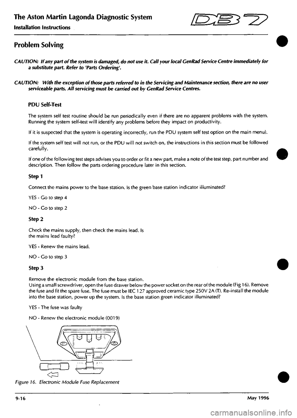
Using a small screwdriver, open the fuse drawer below the power socket on the rear of the module (Fig 16). Remove
the fuse and fit the spare fuse. The fuse must be lEC 127 approved ceramic type 250V 2A (T). Re-install the module
into the base station, power up the system. Is the base station green indicator illuminated?
YES - The fuse was faulty
NO - Renew the electronic module (0019)
Figure 16. Electronic Module Fuse Replacement
9-16 May 1996
Page 373 of 421
The Aston Martin Lagonda Diagnostic System
Installation Instructions ^=2?
Warranty
The Aston Martin Diagnostic System is covered by a one year warranty. Should any of the electrical components
fail during the warranty period, contact your local GenRad Service Centre for a replacement part. Note that the
warranty does not include physical damage.
Spare Parts
Refer to the Aston Martin Diagnostic System Users Guide for a full parts list. All spare parts should be obtained from
your local GenRad Service Centre who can advise you on current prices.
Servicing and Maintenance
CA UTION: With the exception of those parts listed in this section, there are no user serviceable parts within the
system. All servicing must be carried out by GenRad Service Centres.
Battery Testing.
The NICAD batteries fitted in the PDU are designed to be rechargeable and should normally last through many
recharge cycles. Battery life of three to five years can be expected. The capacity of new batteries improves after
several charging cycles. After extended use, they may require renewing. The following procedure will assist you to
determine when renewal is required. Do not use this procedure with new batteries or with a new PDU.
Testing Procedure
1.
Remove all cables from the PDU.
2.
Switch the PDU on and leave it until it switches off (the power on indicator will extinguish)
3. Connect the PDU to the base station for at least 12 hours charging.
4.
Remove all cables from the PDU, switch on the PDU and start timing.
5. If the PDU switches off in less than 30 minutes, the batteries should be renewed.
Changing the Battery Pack
CAUTION: Always read and follow safety warnings and instructions printed on the equipment. The rechargeable
NICAD batteries fitted to the PDU are of a special type. They must only be substituted by GenRad approved parts.
Do not substitute the batteries with any other type. Always dispose of old batteries in compliance with local
recycling regulations.
Battery Changing Procedure
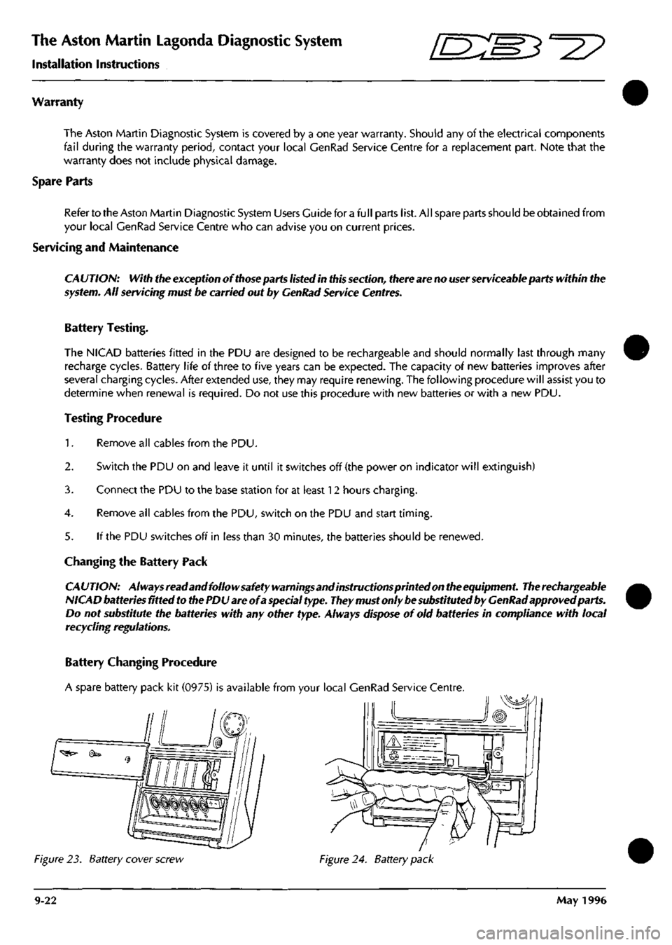
A spare battery pack kit (0975) is available from your local GenRad Service Centre.
Figure 23. Battery cover screw Figure 24. Battery pack
9-22 May 1996