fuses ASTON MARTIN DB7 1997 Workshop Manual
[x] Cancel search | Manufacturer: ASTON MARTIN, Model Year: 1997, Model line: DB7, Model: ASTON MARTIN DB7 1997Pages: 421, PDF Size: 9.31 MB
Page 27 of 421

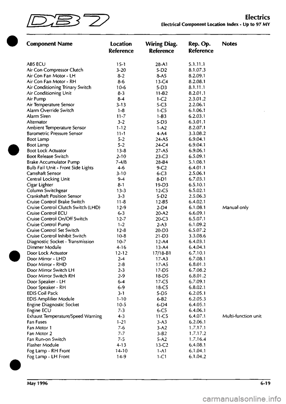
Electrics
Electrical Component Location Index - Up to 97 MY
Component Name
ABS ECU
Air Con Compressor Clutch
Air Con Fan Motor - LH
Air Con Fan Motor - RH
Air Conditioning Trinary Switch
Air Conditioning Unit
Air Pump
Air Temperature Sensor
Alarm Override Switch
Alarm Siren
Alternator
Ambient Temperature Sensor
Barometric Pressure Sensor
Boot Lamp
Boot Lamp
Boot Lock Actuator
Boot Release Switch
Brake Accumulator Pump
Bulb Fail Unit - Front Side Lights
Camshaft Sensor
Central Locking Unit
Cigar Lighter
Column Switchgear
Crankshaft Position Sensor
Cruise Control Brake Switch
Cruise Control Clutch Switch (LHD)
Cruise Control ECU
Cruise Control On/Off Switch
Cruise Control Pump
Cruise Control Set Switch
Cruise Control Inhibit Switch
Diagnostic Socket - Transmission
Dimmer Module
Door Lock Actuator
Door Mirror- LHD
Door Mirror- RHD
Door Mirror Switch LH
Door Mirror Switch RH
Door Speaker -LH
Door Speaker - RH
EDIS Coil Pack
EDIS Amplifier Module
Engine Diagnostic Socket
Engine ECU
Exhaust Temperature/Speed Warning
Fan Fuses
Fan Motor 1
Fan Motor 2
Fan Run-on Switch
Flasher Module
Fog Lamp - RH Front
Fog Lamp - LH Front
Location
Reference
15-1
3-20
8-2
8-6
10-6
8-3
8-4
3-13
1-8
11-7
3-2
1-12
11-1
5-2
5-2
13-8
2-10
7-4/8
4-6
3-10
9-4
8-1
13-3
3-3
11-8
12-9
6-3
12-7
1-2
12-8
10-8
10-7
4-16
12-12
2-4
2-8
2-3
2-9
6-4
6-9
3-1
1-10
10-5
7-3
4-3
1-21
7-6
7-7
7-5
4-13
14-10
14-9
Wiring Diag.
Reference
28-A1
5-D2
8-A5
13-C4
5-D3
11-82
1-C2
5-C3
1-C5
1-B3
5-D3
1-A2
4-A4
24-A5
24-C4
27-A5
l-i-C3
28-84
9-C2
6-C3
8-D1
19-D3
12-C5
5-D2
12-85
2-D4
20-A2
20-C3
2-A3
20-D3
21-D3
12-A4
13-A4
17/18-B1
17-A3
17-A5
17-D5
18-D5
17-C5
18-C5
5-D5
6-B2
6-D4
6-C5
11-C5
3-A3
3-A2
3-B2
5-A2
13-C2
1-A1
1-C1
Rep.
Op. Notes
Reference
5.1.11.1
8.1.07.3
8.2.09.1
8.2.08.1
8.1.11.1
8.2.01.1
2.3.01.2
2.2.06.1
6.1.06.1
6.2.03.1
6.3.01.1
8.2.07.1
3.3.08.2
6.9.04.1
6.9.04.1
6.9.06.1
6.5.09.1
5.1.08.1
6.4.01.1
2.5.06.1
6.7.03.1
6.5.10.1
6.5.02.1
2.5.06.3
6.4.02.1
6.1.08.1 Manual only
6.6.09.1
6.5.07.1
6.1.09.2
6.5.07.2
3.3.08.6
6.4.03.1
6.4.04.1
6.7.10.1
6.7.08.1
6.8.01.1
6.7.08.2
6.8.01.2
6.7.09.1
6.8.02.1
6.2.05.1
6.2.05.3
6.4.05.1
6.4.06.1
6.4.07.1 Multi-functio
6.2.06.1
1.7.17.1
1.7.17.2
1.7.16.4
6.4.08.1
6.1.04.1
6.1.04.2
May 1996 6-19
Page 129 of 421

Electrics
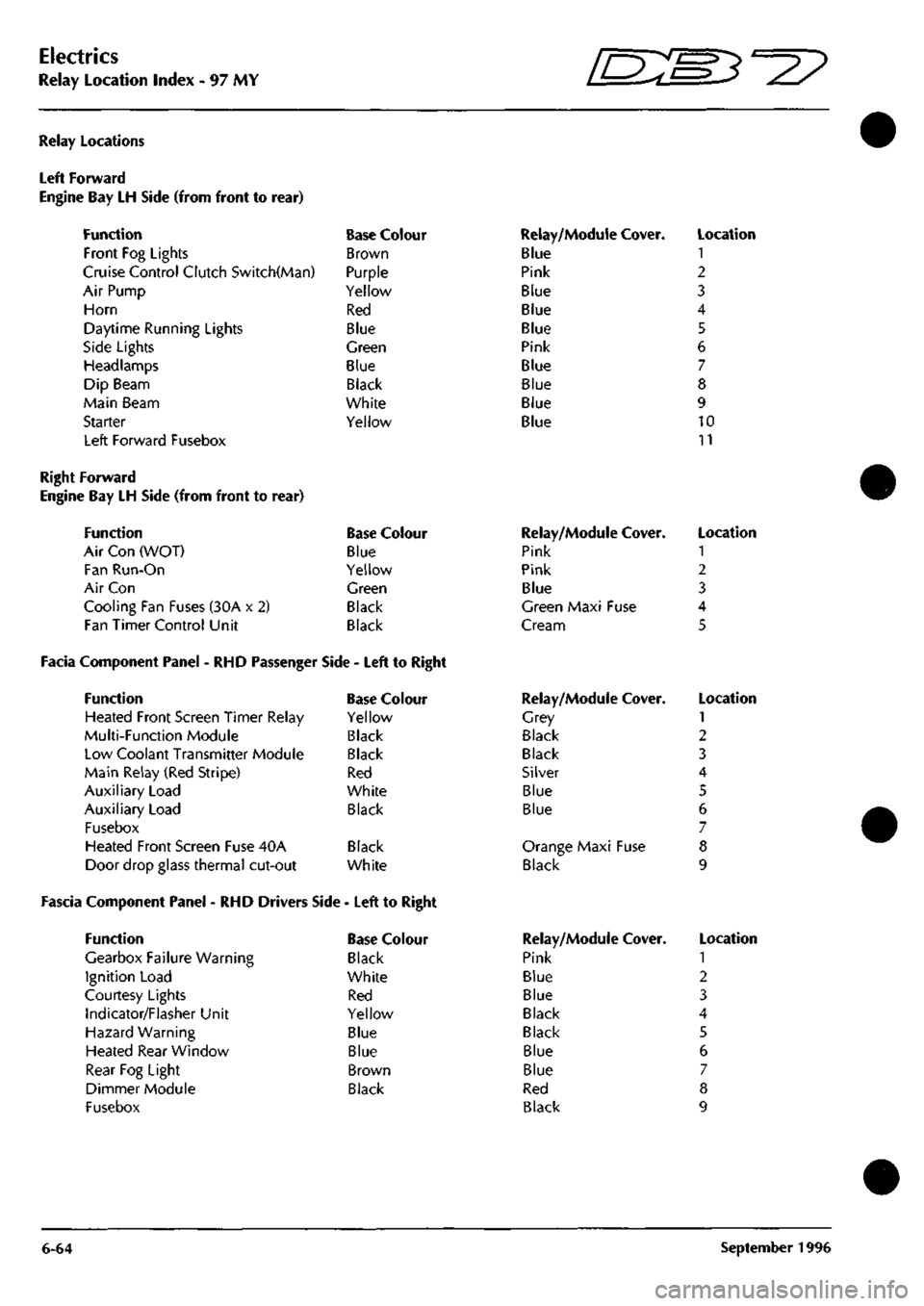
Relay Location Index - 97 MY 5^^?
Relay Locations
Left Forward
Engine Bay LH Side (from front to
Function
Front Fog Lights
rear)
Cruise Control Clutch Switch(Man)
Air Pump
Horn
Daytime Running Lights
Side Lights
Headlamps
Dip Beam
Main Beam
Starter
Left Forward Fusebox
Base Colour
Brown
Purple
Yellow
Red
Blue
Green
Blue
Black
White
Yellow
Relay/Module Cover.
Blue
Pink
Blue
Blue
Blue
Pink
Blue
Blue
Blue
Blue
Location
1
2
3
4
5
6
7
8
9
10
11
Right Forward
Engine Bay LH Side (from front to rear)
Function Base Colour
Air Con (WOT) Blue
Fan Run-On Yellow
Air Con Green
Cooling Fan Fuses (30A x 2) Black
Fan Timer Control Unit Black
Facia Component Panel - RHD Passenger Side - Left to Right
Function Base Colour
Heated Front Screen Timer Relay Yellow
Multi-Function Module Black
Low Coolant Transmitter Module Black
Main Relay (Red Stripe) Red
Auxiliary Load White
Auxiliary Load Black
Fusebox
Heated Front Screen Fuse 40A Black
Door drop glass thermal cut-out White
Fascia Component Panel - RHD Drivers Side - Left to Right
Function
Gearbox Failure Warning
Ignition Load
Courtesy Lights
Indicator/Flasher Unit
Hazard Warning
Heated Rear Window
Rear Fog Light
Dimmer Module
Fusebox
Base Colour
Black
White
Red
Yellow
Blue
Blue
Brown
Black
Relay/Module
Pink
Pink
Blue
Cover.
Green Maxi Fuse
Cream
Relay/Module
Grey
Black
Black
Silver
Blue
Blue
Cover.
Orange Maxi Fuse
Black
Relay/Module
Pink
Blue
Blue
Black
Black
Blue
Blue
Red
Black
Cover.
Location
1
2
3
4
5
Location
1
2
3
4
5
6
7
8
9
Location
1
2
3
4
5
6
7
8
9
6-64 September 1996