height adjustment ASTON MARTIN DB7 1997 Workshop Manual
[x] Cancel search | Manufacturer: ASTON MARTIN, Model Year: 1997, Model line: DB7, Model: ASTON MARTIN DB7 1997Pages: 421, PDF Size: 9.31 MB
Page 227 of 421

3-^?
Electrics
Seat Removal/Replacement 97.5 MY
6.6.03
Seat Removal 97.5 MY
Description
The 97.5 MY front seats are common to the DB7
Coupe
and
Volante
models.
Seat
switch
assembi ies
are located on the outboard side of both driver and
passenger
seats.
The front switch controls fore and
aft movement and the seat height adjustment. The
centre switch controls the recline adjustment. The
rear switch
controls
the
lumbar support adjustment.
The seat
heater switches are mounted on the centre
console, forward of the gear selector
lever.
Only one of
the
slide,
recline or height motors can
be driven under manual control at any one time.
Each seat switch pack is hard wired to the relevant
Seat Control
Module
beneath each
seat.
The
module
outputs are hard wired to the seat motors.
Removal
WARNING -
Seat
belt
Pretensioners
(if fitted):
To avoid the possibility
of
personal
injury
caused
by accidental deployment of the seat belt
pretensioner,
disconnect
the
vehicle battery and
wait at
least
10
minutes
for all
voltages
to fully
discharge
before working on the
pretensioner
system.
This covers the possibility
of
the normal
capacitor
discharge
circuits being inoperative and
failing to discharge the detonator capacitor when
instructed
to
do
so.
Procedure
1.
Motortheseatto
its
maximum forward position and
remove the fixings at the rear of the slides.
2.
Motor the seat to its maximum rearward position
and remove the front seat slide fixings.
3. Disconnect the battery
ground
(black)
lead.
Wait at
least 10 minutes for the pretensioner power supply
to fully discharge before working on the seat if a
pretensioner is fitted.
Note: Disconnect the battery within 12 seconds of
switching off the ignition to avoid the alarm siren sounding.
4.
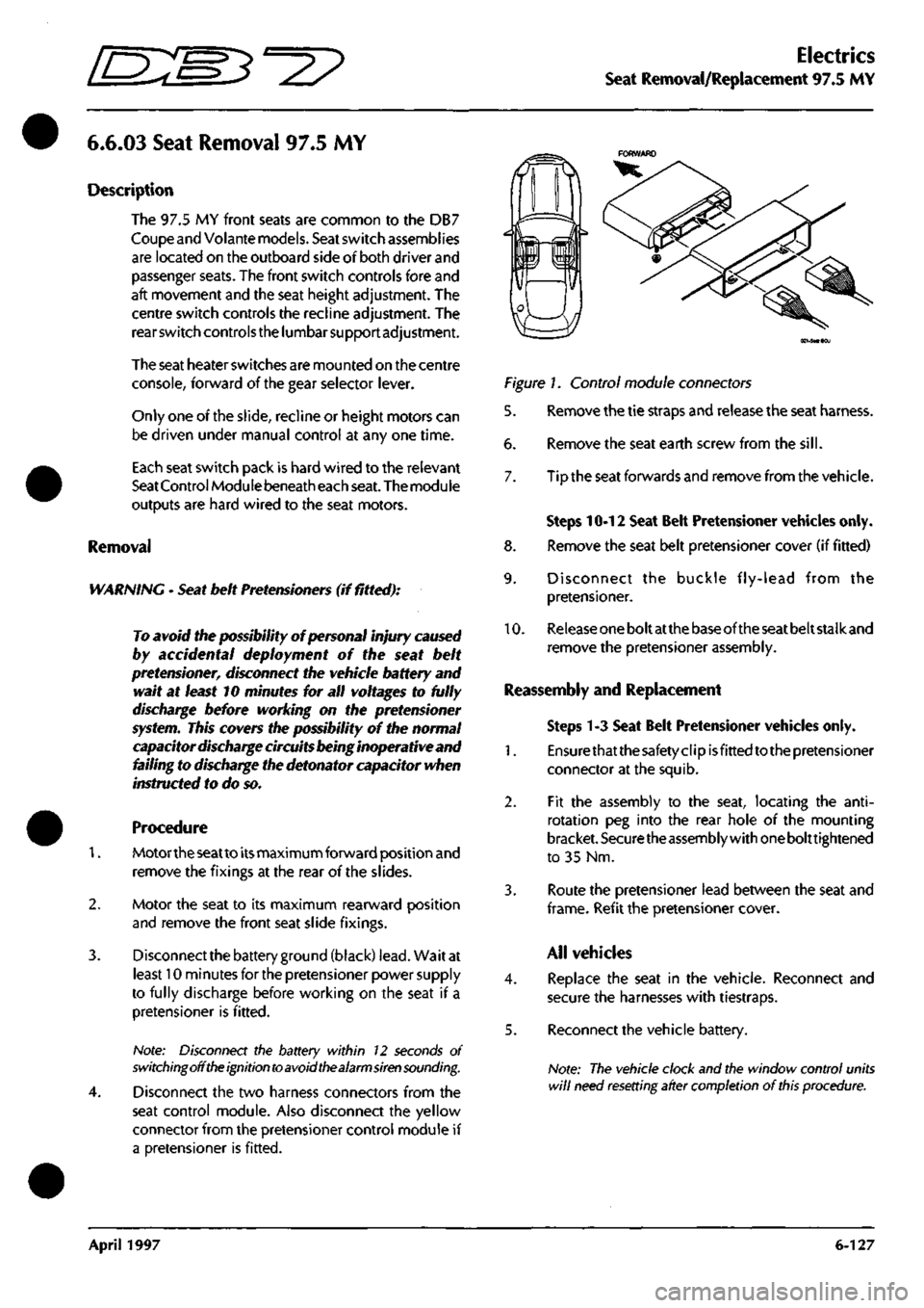
Disconnect the two harness connectors from the
seat control module. Also disconnect the yellow
connector from the pretensioner control module if
a pretensioner is fitted.
Figure 1. Control module connectors
5. Remove the tie straps and release the seat harness.
6. Remove the seat earth screw from the
sill.
7. Tip the seat forwards and remove from the vehicle.
Steps 10-12 Seat Belt Pretensioner vehicles only.
8. Remove the seat belt pretensioner cover (if fitted)
9. Disconnect the buckle fly-lead from the
pretensioner.
10.
Release
one
bolt at
the
base of the
seat
belt stalk and
remove the pretensioner assembly.
Reassembly and Replacement
Steps 1-3 Seat Belt Pretensioner vehicles only.
1.
Ensurethatthesafetyclipisfittedtothepretensioner
connector at the squib.
2.
Fit the assembly to the seat, locating the
anti-
rotation peg into the rear hole of the mounting
bracket.
Securethe
assembly with
one
bolttightened
to 35 Nm.
3. Route the pretensioner lead between the seat and
frame.
Refit the pretensioner
cover.
All vehicles
4.
Replace the seat in the vehicle. Reconnect and
secure the harnesses with tiestraps.
5. Reconnect the vehicle battery.
Note:
The vehicle clock and the window control units
will
need resetting after completion
of
this
procedure.
April 1997 6-127
Page 275 of 421

Body and Trim
Door Glass Adjustment ^?
9.2.01.8 - Door Glass Adjustment
The door glass can be adjusted in three planes. Lateral, Up and Down, and Front to Rear. It is advisable however
to avoid forward and rearward adjustment if possible,
as
this will affect the height and overall position of
the
glass
relative to the seals. Use this adjustment only to correct serious misalignment.
Lateral Adjustment
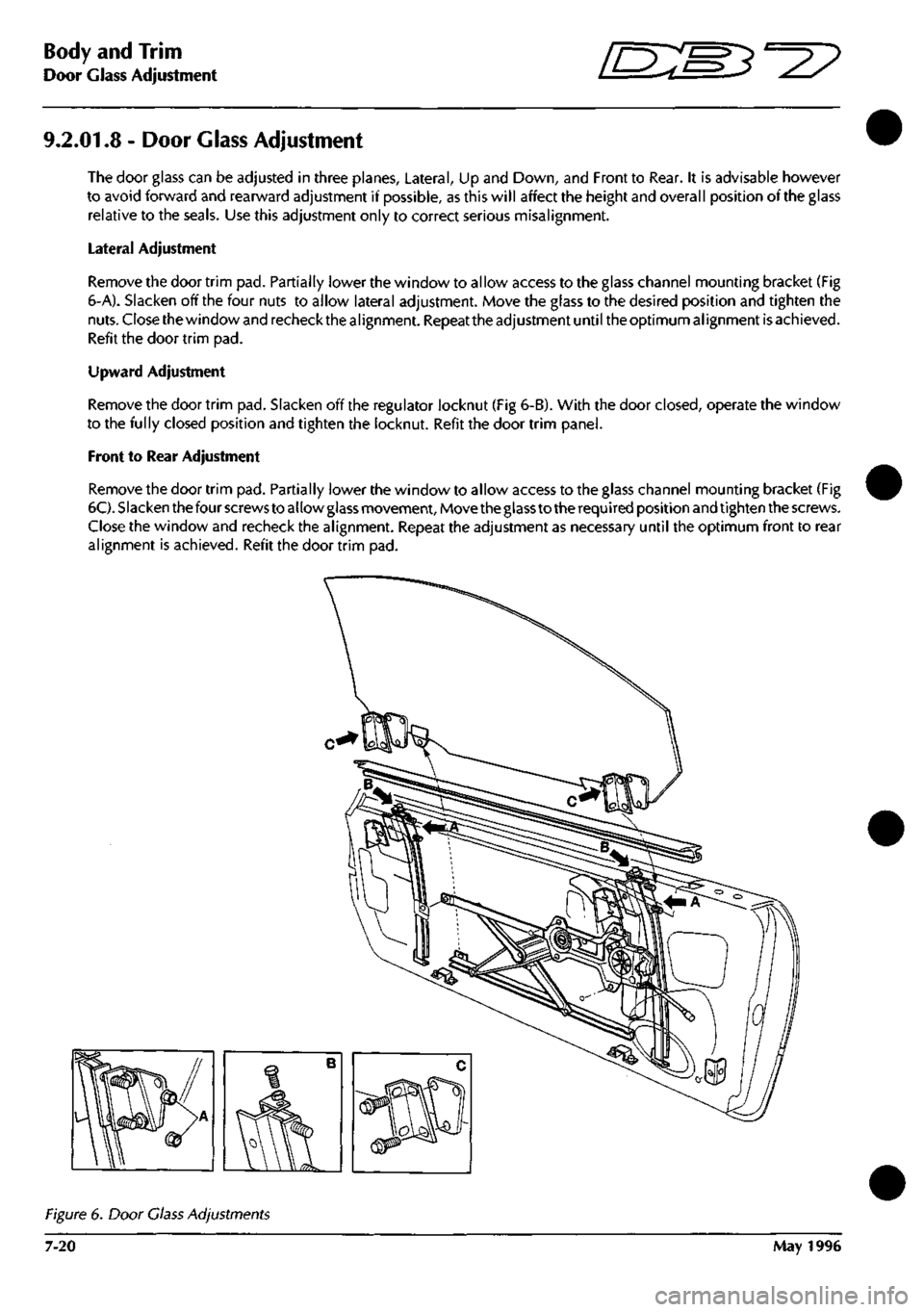
Remove the door trim pad. Partially lower the window to allow access to the glass channel mounting bracket (Fig
6-A). Slacken off the four nuts to allow lateral adjustment. Move the glass to the desired position and tighten the
nuts.
Close the
window
and
recheck the alignment.
Repeat the
adjustment until
the
optimum alignment
is
achieved.
Refit the door trim pad.
Upward Adjustment
Remove the door trim pad. Slacken off the regulator locknut (Fig 6-B). With the door
closed,
operate the window
to the fully closed position and tighten the locknut. Refit the door trim panel.
Front to Rear Adjustment
Remove the door trim pad. Partially lower the window to allow access to the glass channel mounting bracket (Fig
6C).
Slacken
the
four
screws
to allow
glass
movement.
Move
theglass
to the
required position
and tighten
the screws.
Close the window and recheck the alignment. Repeat the adjustment as necessary until the optimum front to rear
alignment is achieved. Refit the door trim pad.
Figure
6. Door
Class Adjustments
7-20 May 1996
Page 328 of 421

^?
Air Conditioning Repair Procedures
Compressor Removal
8.1.01.1 Compressor Removal/Renewal
Procedure
1.
Open the bonnet and fit a wing cover.
2.
Depressurise the air conditioning system.
3.
6.
7.
8.
9.
Disconnect the low and high pressure hoses from
the rear of the compressor. Plug the hose ends to
prevent the ingress of dirt.
Remove the compressor pivot bolt securing nut.
Carefully separate the muffler from the compressor
and remove and discard the 'O' ring
seal.
Fit a blanking plug to the muffler and a blanking
plate to the compressor, fit and tighten the bolt that
secures blanking plate.
Raise the vehicle to working height on a ramp.
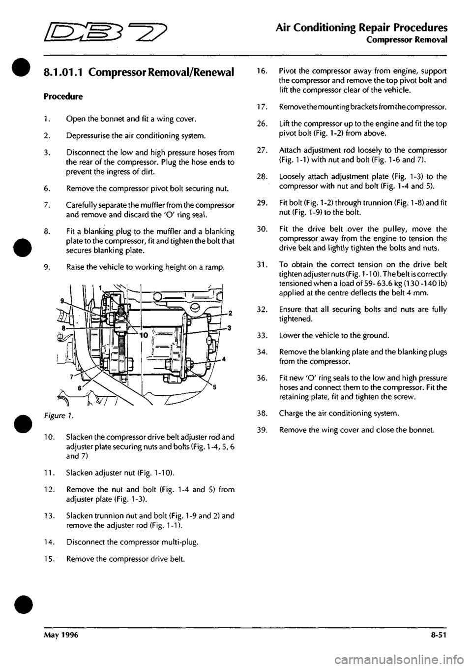
Figure 7.
10.
Slacken the compressor drive belt adjuster rod and
adjuster plate securing nuts and bolts (Fig.
1
-4, 5, 6
and 7)
11.
Slacken adjuster nut (Fig.
1
-10).
12.
Remove the nut and bolt (Fig. 1-4 and 5) from
adjuster plate (Fig. 1-3).
13.
Slacken trunnion nut and bolt (Fig.
1
-9 and 2) and
remove the adjuster rod (Fig. 1-1).
14.
Disconnect the compressor multi-plug.
1
5. Remove the compressor drive belt.
16.
Pivot the compressor away from engine, support
the compressor and remove the top pivot bolt and
lift the compressor clear of the vehicle.
17.
Removethemountingbracketsfromthecompressor.
26.
Lift the compressor up to the engine and fit the top
pivot bolt (Fig.
1
-2) from above.
27.
Attach adjustment rod loosely to the compressor
(Fig.
1
-1) with nut and bolt (Fig.
1
-6 and 7).
28.
Loosely attach adjustment plate (Fig. 1-3) to the
compressor with nut and bolt (Fig.
1
-4 and 5).
29.
Fit bolt (Fig.
1
-2) through trunnion (Fig.
1
-8) and fit
nut (Fig. 1-9) to the bolt.
30.
Fit the drive belt over the pulley, move the
compressor away from the engine to tension the
drive belt and lightly tighten the bolts and nuts.
31.
To obtain the correct tension on the drive belt
tighten adjuster nuts
(Fig.
1
-10). The belt
is
correctly
tensioned when a load of 59- 63.6 kg (130 -140 lb)
applied at the centre deflects the belt 4 mm.
32.
Ensure that all securing bolts and nuts are fully
tightened.
33.
Lowerthe vehicle to the ground.
34.
Remove the blanking plate and the blanking plugs
from the compressor.
36.
Fit new 'O' ring seals to the low and high pressure
hoses and connect them to the compressor. Fit the
retaining plate, fit and tighten the screw.
38.
Charge the air conditioning system.
39.
Remove the wing cover and close the bonnet.
May 1996 8-51