spring ASTON MARTIN DB7 1997 Workshop Manual
[x] Cancel search | Manufacturer: ASTON MARTIN, Model Year: 1997, Model line: DB7, Model: ASTON MARTIN DB7 1997Pages: 421, PDF Size: 9.31 MB
Page 13 of 421

[EM^^^
Electrics
Wiper Motor / Alternator - Removal Procedures
6.2.01 Windscreen Wiper Motor 6.3.01 Alternator
Procedure
1.
Disconnect the battery.
2.
Disconnect the wiper motor multi-plug.
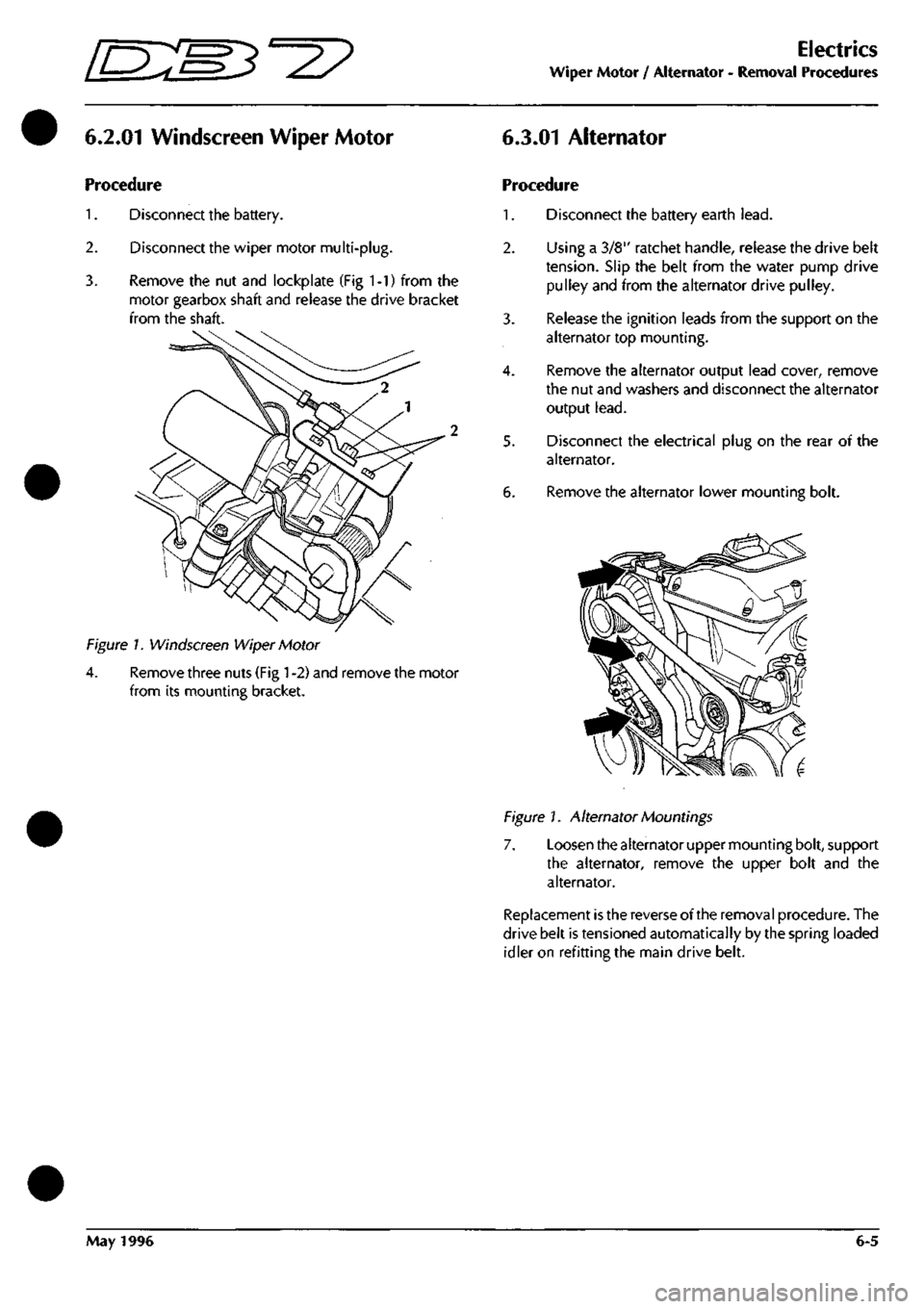
3. Remove the nut and lockplate (Fig 1-1) from the
motor gearbox shaft and release the drive bracket
from the shaft.
Figure 1. Windscreen Wiper Motor
4.
Remove three nuts (Fig
1
-2) and remove the motor
from its mounting bracket.
Procedure
1.
Disconnect the battery earth
lead.
2.
Using a 3/8" ratchet handle, release the drive belt
tension.
Slip the belt from the water pump drive
pulley and from the alternator drive pulley.
3. Release the ignition leads from the support on the
alternator top mounting.
4.
Remove the alternator output lead cover, remove
the nut and washers and disconnect the alternator
output
lead.
5. Disconnect the electrical plug on the rear of the
alternator.
6. Remove the alternator lower mounting bolt.
Figure 1. Alternator Mountings
7. Loosen the alternator upper mounting bolt, support
the alternator, remove the upper bolt and the
alternator.
Replacement is the reverse of the removal procedure. The
drive belt is tensioned automatically by the spring loaded
idler on refitting the main drive belt.
May 1996 6-5
Page 17 of 421

lEM^-^?
Electrics
Control Switch - Removal Procedures
6.5.07 Cruise Control, Window and
Gearshift Switches
Procedure
1.
Protect the wood finisher around the switches.
6.5.08 Seat Control Switch Panels
Procedure
1.
Remove the wood trim above the passenger side
dash.
2.
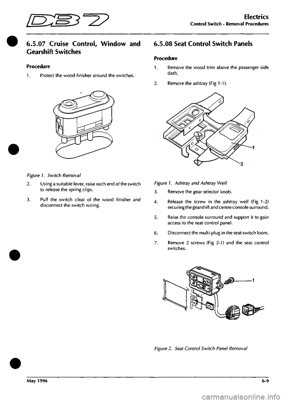
Remove the ashtray (Fig
1
-1).
Figure 7. Switch Removal
2.
Using a suitable lever, raise each end of the switch
to release the spring clips.
3. Pull the switch clear oi the wood finisher and
disconnect the switch wiring.
Figure!. Ashtray and Ashtray Well
3. Remove the gear selector knob.
4.
Release the screw in the ashtray well (Fig 1-2)
securing the gearshift and centre console surround.
5. Raise the console surround and support it to gain
access to the seat control panel.
6. Disconnect the multi-plug in the seat switch loom.
7. Remove 2 screws (Fig 2-1) and the seat control
switches.
Figure 2. Seat Control Switch Panel Removal
May 1996 6-9
Page 360 of 421

^^?
The Aston Martin Lagonda Diagnostic System
I nstal lation I nstructions
Bench Mounting
The base station may also be mounted on a bench, which
must be in a safe position, stable and protected form
hazards and impacts. The base station must be mounted
at the back of the bench. 'Z' clips are provided for
permanent mounting. The bench surface must be kept free
from dust at all times.
CAUTION:
A gap under the base station must be
maintained free from obstructions to allow a flow of air
under the unit for cooling.
Electronic Module installation
WARNING: The base station electronic module must be
disconnected from the mains supply prior to installation/
removal from the base station assembly. DO NOT
reconnect to the mains supply until the module is safely
fitted into the base station. This unit must be earthed.
Note:
Users in North America are advised to replace the
ceramic mains fuse in the electronic module with theglass
fuse supplied.
Procedure
1.
Unlock the base station door
2.
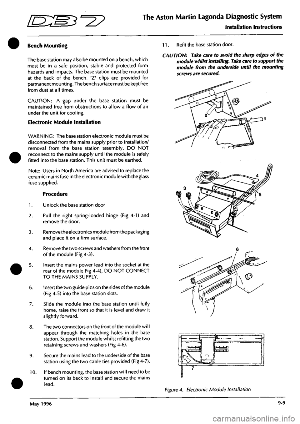
Pull the right spring-loaded hinge (Fig 4-1) and
remove the door.
3. Removetheelectronicsmodulefrom the packaging
and place it on a firm surface.
4.
Remove the two screws and washers from the front
of the module (Fig 4-3).
5. Insert the mains power lead into the socket at the
rear of the module Fig 4-4), DO NOT CONNECT
TO THE MAINS SUPPLY.
6. Insert the two guide pins on the sides of the module
(Fig 4-5) into the base station slots.
7. Slide the module into the base station until fully
home,
raise the front so that it is level and draw it
slightly forward.
8. The two connectors on the front of the module will
appear through the matching holes in the base
station.
Support the module whilst refitting the two
retaining screws and washers (Fig 4-6).
9. Secure the mains lead to the underside of the base
station using the two cable ties provided (Fig 4-7).
10.
If bench mounting, the base station will need to be
turned on its back to install and secure the mains
lead.
11.
Refit the base station door.
CAUTION: Take care to avoid the sharp edges of the
module whilst installing. Take care to support the
module from the underside until the mounting
screws are secured.
Figure 4. Electronic Module Installation
May 1996 9-9