thermal cut out for window ASTON MARTIN DB7 1997 Workshop Manual
[x] Cancel search | Manufacturer: ASTON MARTIN, Model Year: 1997, Model line: DB7, Model: ASTON MARTIN DB7 1997Pages: 421, PDF Size: 9.31 MB
Page 22 of 421

Electrics
Electric Windows - Fault Analysis / Window Motor Removal
[n:m3^^
Electric Windows
Description
Power to the window wind circuits is available
when the ignition switch is on and is supplied
through a thermal cut-out to the left and right
window switches. The switches are double pole
plus earth so that the current through a window
motor may be switched in either direction to raise
or lower the window.
DB7 uses frameless door windows which seal
against rubber strips around the body shell door
opening.
To avoid damaging these seals during
door opening, the door glass must be lowered
before the door can be opened. This function is
controlled by the window control units. The units
are mounted on the inside of each door frame and
will sense if a door handle is pulled to open the
door. Before releasing the door lock, the control
unit will drive the window wind motor briefly to
lower the door window glass down until it clears
the window seals. Similarly, after closing a door,
the window motor will be run to raise the door glass
to seat the glass against the body seals.
Fault Analysis Procedure
a) If a window fails to operate, check for fuse failure
and the connectors for poor or open contacts.
b) Check the thermal cut-out by shorting across it and
operating either window. If the windows operate
with the short
ci rcu
it but not without, the cut-out is
faulty.
c) With the ignition on, battery voltage should be
available between the inputterminalsof the switches
and chassis. Operate each switch and ensure that
battery voltage is available between the switch
output terminals and chassis.
d) Measure voltagefrom each switch inputterminalto
the switch earth return terminal. If no voltage is
measured,
the earth return line is open circuit.
e) Measure continuity through the wiring from the
switches to each motor. If continuity is correct,
remove the motor for bench testing.
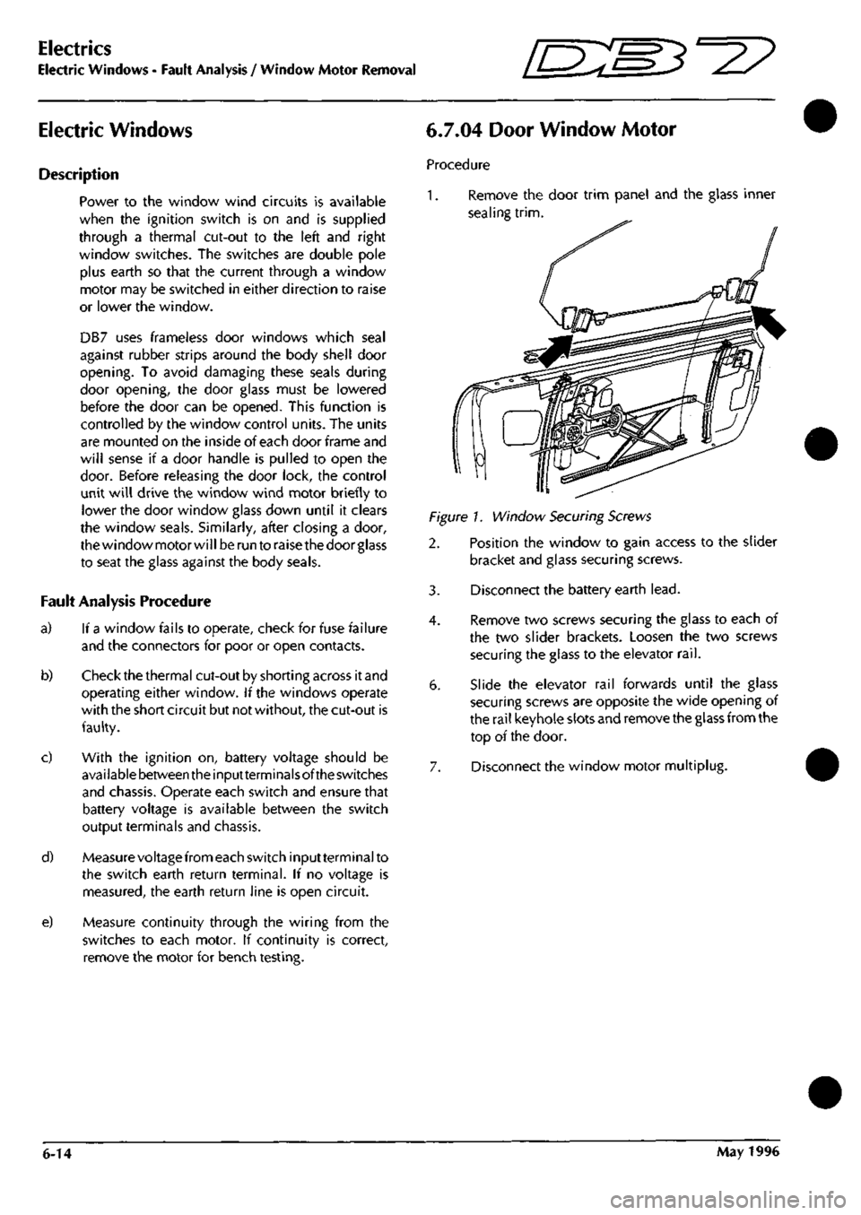
6.7.04 Door Window Motor
Procedure
1.
Remove the door trim panel and the glass inner
sealing
trim.
Figure!. Window Securing Screws
2. Position the window to gain access to the slider
bracket and glass securing screws.
3. Disconnect the battery earth
lead.
4.
Remove two screws securing the glass to each of
the two slider brackets. Loosen the two screws
securing the glass to the elevator
rail.
6. Slide the elevator rail forwards until the glass
securing screws are opposite the wide opening of
the rail keyhole slots and remove the glass from the
top of the door.
7. Disconnect the window motor multiplug.
6-14 May 1996
Page 129 of 421

Electrics
Relay Location Index - 97 MY 5^^?
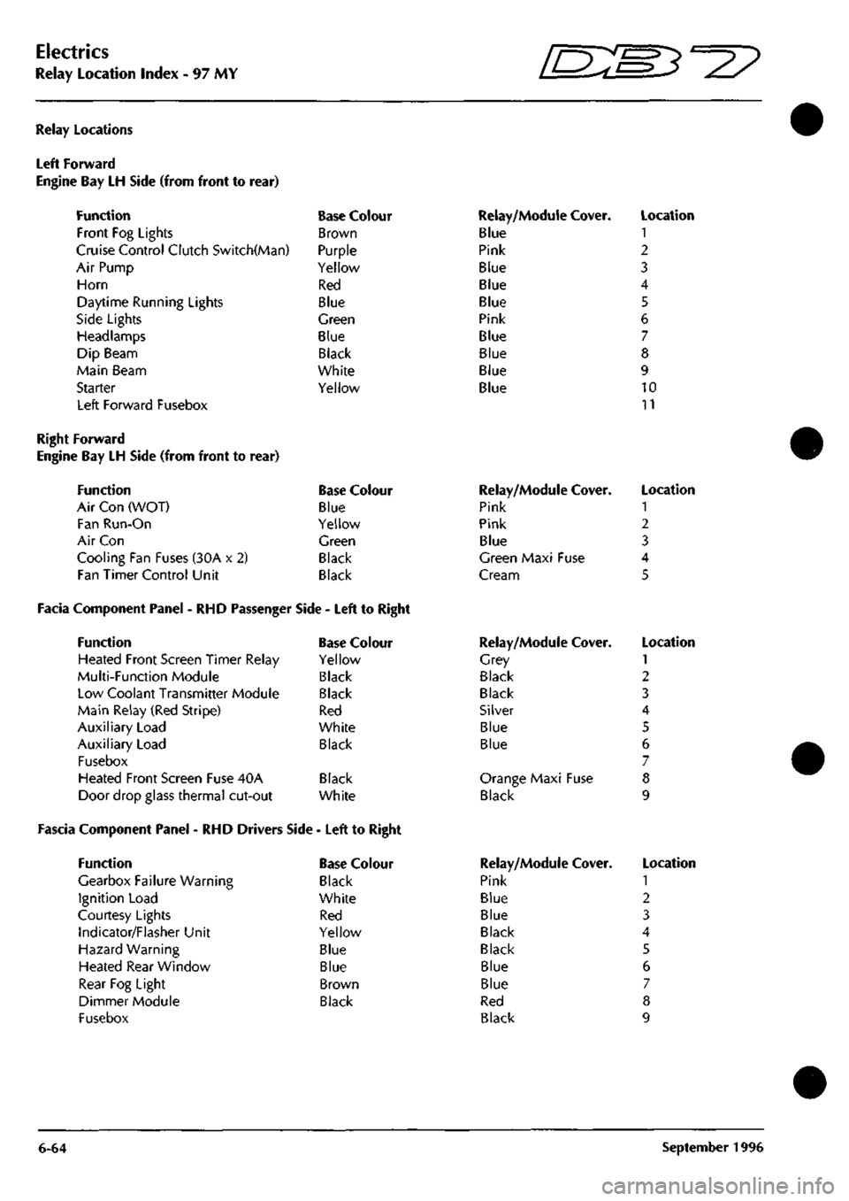
Relay Locations
Left Forward
Engine Bay LH Side (from front to
Function
Front Fog Lights
rear)
Cruise Control Clutch Switch(Man)
Air Pump
Horn
Daytime Running Lights
Side Lights
Headlamps
Dip Beam
Main Beam
Starter
Left Forward Fusebox
Base Colour
Brown
Purple
Yellow
Red
Blue
Green
Blue
Black
White
Yellow
Relay/Module Cover.
Blue
Pink
Blue
Blue
Blue
Pink
Blue
Blue
Blue
Blue
Location
1
2
3
4
5
6
7
8
9
10
11
Right Forward
Engine Bay LH Side (from front to rear)
Function Base Colour
Air Con (WOT) Blue
Fan Run-On Yellow
Air Con Green
Cooling Fan Fuses (30A x 2) Black
Fan Timer Control Unit Black
Facia Component Panel - RHD Passenger Side - Left to Right
Function Base Colour
Heated Front Screen Timer Relay Yellow
Multi-Function Module Black
Low Coolant Transmitter Module Black
Main Relay (Red Stripe) Red
Auxiliary Load White
Auxiliary Load Black
Fusebox
Heated Front Screen Fuse 40A Black
Door drop glass thermal cut-out White
Fascia Component Panel - RHD Drivers Side - Left to Right
Function
Gearbox Failure Warning
Ignition Load
Courtesy Lights
Indicator/Flasher Unit
Hazard Warning
Heated Rear Window
Rear Fog Light
Dimmer Module
Fusebox
Base Colour
Black
White
Red
Yellow
Blue
Blue
Brown
Black
Relay/Module
Pink
Pink
Blue
Cover.
Green Maxi Fuse
Cream
Relay/Module
Grey
Black
Black
Silver
Blue
Blue
Cover.
Orange Maxi Fuse
Black
Relay/Module
Pink
Blue
Blue
Black
Black
Blue
Blue
Red
Black
Cover.
Location
1
2
3
4
5
Location
1
2
3
4
5
6
7
8
9
Location
1
2
3
4
5
6
7
8
9
6-64 September 1996