brake ASTON MARTIN V8 VANTAGE 2010 Owners Manual
[x] Cancel search | Manufacturer: ASTON MARTIN, Model Year: 2010, Model line: V8 VANTAGE, Model: ASTON MARTIN V8 VANTAGE 2010Pages: 947, PDF Size: 43.21 MB
Page 752 of 947
Torque Figures
Appendix & Glossary
May 2007 Workshop Manual 20-1-13
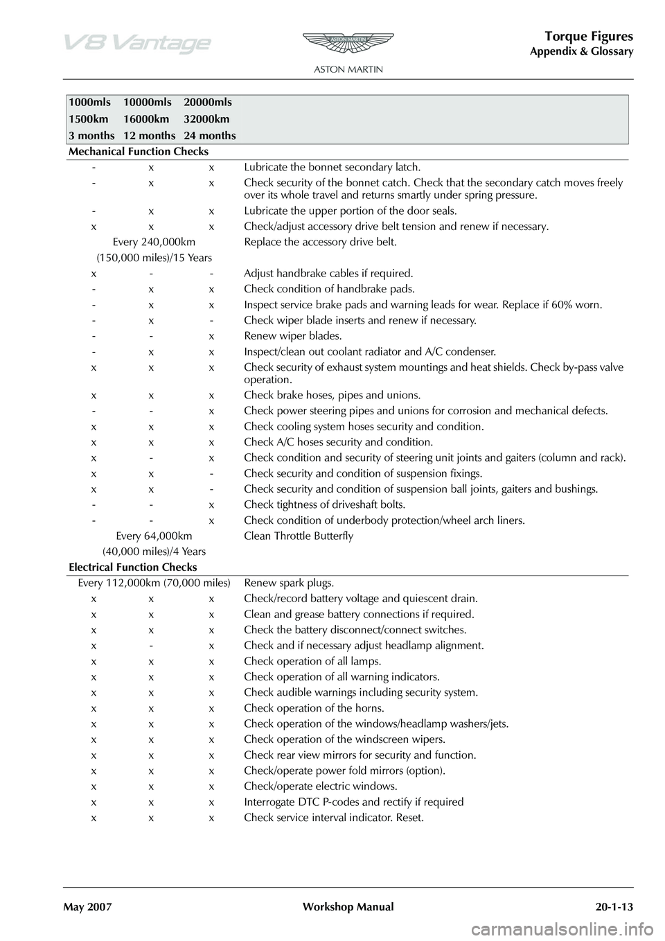
Mechanical Function Checks - x x Lubricate the bonnet secondary latch.
- x x Check security of the bonnet catch. Ch eck that the secondary catch moves freely
over its whole travel and returns smartly under spring pressure.
- x x Lubricate the upper portion of the door seals.
x x x Check/adjust accessory drive belt tension and renew if necessary. Every 240,000km
(150,000 miles)/15 Years Replace the accessory drive belt.
x - - Adjust handbrake cables if required. - x x Check condition of handbrake pads.
- x x Inspect service brake pads and warnin g leads for wear. Replace if 60% worn.
- x - Check wiper blade inserts and renew if necessary.
- - x Renew wiper blades.
- x x Inspect/clean out coolant radiator and A/C condenser.
x x x Check security of exhaust system mountings and heat shields. Check by-pass valve operation.
x x x Check brake hoses, pipes and unions. - - x Check power steering pipes and unions for corrosion and mechanical defects.
x x x Check cooling system hoses security and condition.
x x x Check A/C hoses security and condition.
x - x Check condition and security of steering unit joints and gaiters (column and rack).
x x - Check security and condition of suspension fixings.
x x - Check security and condition of susp ension ball joints, gaiters and bushings.
- - x Check tightness of driveshaft bolts.
- - x Check condition of underbody protection/wheel arch liners.
Every 64,000km
(40,000 miles)/4 Years Clean Throttle Butterfly
Electrical Function Checks Every 112,000km (70,000 miles) Renew spark plugs. x x x Check/record battery voltage and quiescent drain.
x x x Clean and grease battery connections if required.
x x x Check the battery disconnect/connect switches.
x - x Check and if necessary adjust headlamp alignment.
x x x Check operation of all lamps.
x x x Check operation of all warning indicators.
x x x Check audible warnings including security system.
x x x Check operation of the horns.
x x x Check operation of the windows/headlamp washers/jets.
x x x Check operation of the windscreen wipers.
x x x Check rear view mirrors for security and function.
x x x Check/operate power fold mirrors (option).
x x x Check/operate electric windows.
x x x Interrogate DTC P-codes and rectify if required
x x x Check service interval indicator. Reset.
1000mls
1500km
3 months10000mls
16000km
12 months20000mls
32000km
24 months
Page 832 of 947
Electronics Training Programme
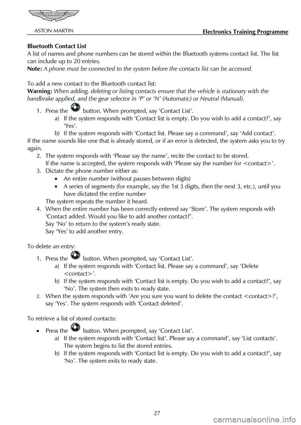
Bluetooth Contact List
A list of names and phone numbers can be stored wi thin the Bluetooth systems contact list. The list
can include up to 20 entries.
Note: A phone must be connected to the system be fore the contacts list can be accessed.
To add a new contact to the Bluetooth contact list:
Warning: When adding, deleting or listing contacts en sure that the vehicle is stationary with the
handbrake applied, and the gear selector in ‘P’ or ‘N’ (Automatic) or Neutral (Manual).
1. Press the button. When prompted, say ‘Contact List’.
a) If the system responds with ‘Contact list is empty. Do you wish to add a contact?’, say
‘Yes’.
b) If the system responds with ‘Contact li st. Please say a command’, say ‘Add contact’.
If the name sounds like one that is already stored, or if an error is detected, the system asks you to try
again.
2. The system responds with ‘Please say t he name’, recite the contact to be stored.
If the name is accepted, the system responds with ‘Please say the number for
3. Dictate the phone number either as:
• An entire number (without pauses between digits)
• A series of segments (for example, say the 1st 3 digits, then the next 3, etc.), until you
have dictated the entire number
The system repeats the number it heard.
4. When the entire number has been correctly entered say ‘Store’. The system responds with
‘Contact added. Would you like to add another contact?’.
Say ‘No’ to return to the system’s ready state.
Say ‘Yes’ to add another entry.
To delete an entry:
1. Press the button. When prompted, say ‘Contact List’.
a) If the system responds with ‘Contact list. Please say a command’, say ‘Delete
b) If the system responds with ‘Contact list is empty. Do you wish to add a contact?’, say
‘No’. The system then exits to ready state.
2. When the system responds with ‘Are you sure you want to delete the contact
say ‘Yes’. The system respon ds with ‘Contact deleted’.
To retrieve a list of stored contacts:
• Press the button. When prompted, say ‘Contact List’.
a) If the system responds with ‘Contact list ’. Please say a command’, say ‘List contacts’.
The system begins to list the stored entries.
b) If the system responds with ‘Contact list is empty. Do you wish to add a contact?’, say
‘No’. The system exits to ready state.
27
Page 862 of 947
AML EOBD System Operation Summary
Rory O’Curry Aston Martin Lagonda CONFIDENTIAL 1 May 2009
[email protected] AML EOBD Monitors 07 ROC.doc Page 16 of 43
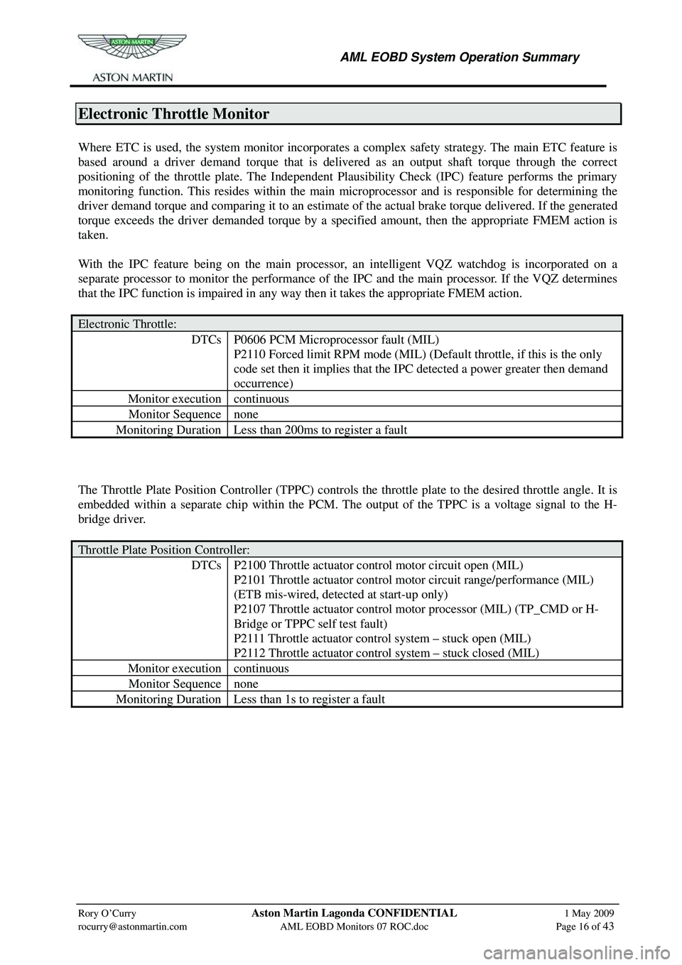
Electronic Throttle Monitor
Where ETC is used, the system monitor incorporates a complex safety strategy. The main ETC feature is
based around a driver demand torque that is deliver ed as an output shaft torque through the correct
positioning of the throttle plate. The Independent Plausibility Check (IPC) feature performs the primary
monitoring function. This resides within the main microprocessor and is responsible for determining the
driver demand torque and comparing it to an estimate of the actual brake torque delivered. If the generated
torque exceeds the driver demanded torque by a speci fied amount, then the appropriate FMEM action is
taken.
With the IPC feature being on the main processor, an intelligent VQZ watchdog is incorporated on a
separate processor to monitor the performance of the IPC and the main processor. If the VQZ determines
that the IPC function is impaired in any way then it takes the appropriate FMEM action.
Electronic Throttle:
DTCs P0606 PCM Microprocessor fault (MIL)
P2110 Forced limit RPM mode (MIL) (Default throttle, if this is the only
code set then it implies that the IPC detected a power greater then demand
occurrence)
Monitor execution continuous
Monitor Sequence none
Monitoring Duration Less than 200ms to register a fault
The Throttle Plate Position Controller (TPPC) controls the throttle plate to the desired throttle angle. It is
embedded within a separate chip within the PCM. The output of the TPPC is a voltage signal to the H-
bridge driver.
Throttle Plate Position Controller:
DTCs P2100 Throttle actuator control motor circuit open (MIL)
P2101 Throttle actuator control motor circuit range/performance (MIL)
(ETB mis-wired, detected at start-up only)
P2107 Throttle actuator control motor processor (MIL) (TP_CMD or H-
Bridge or TPPC self test fault)
P2111 Throttle actuator control system – stuck open (MIL)
P2112 Throttle actuator control system – stuck closed (MIL)
Monitor execution continuous
Monitor Sequence none
Monitoring Duration Less than 1s to register a fault
Page 863 of 947

AML EOBD System Operation Summary
Rory O’Curry Aston Martin Lagonda CONFIDENTIAL 1 May 2009
[email protected] AML EOBD Monitors 07 ROC.doc Page 17 of 43
The system monitor also determines the validity of an y inputs to the electronic throttle control feature by
checking for opens, shorts, out-of-range values and inconsistencies.
Throttle Position Sensors:
DTCs P0121 Throttle position sensor A circ uit range/performance (Closed in bore
out of range fault)
P0122 Throttle position sensor A circuit low input
P0123 Throttle position sensor A circuit high input
P0124 Throttle position sensor A circuit intermittent
P0221 Throttle position sensor B circuit range/performance (Closed in bore
out of range fault)
P0222 Throttle position sensor B circuit low input
P0223 Throttle position sensor B circuit high input
P0224 Throttle position sensor B circuit intermittent
P2135 Throttle position sensor A/B voltage correlation
Monitor execution continuous
Monitor Sequence none
Monitoring Duration Less than 200ms to register a fault
Accelerator Pedal Position Sensors:
DTCs P2121 Pedal position sensor D circuit range/performance
P2122 Pedal position sensor D circuit low input
P2123 Pedal position sensor D circuit high input
P2124 Pedal position sensor D circuit intermittent
P2126 Pedal position sensor E circuit range/performance
P2127 Pedal position sensor E circuit low input
P2128 Pedal position sensor E circuit high input
P2129 Pedal position sensor E circuit intermittent
P2138 Pedal position sensor D/E voltage correlation
Monitor execution continuous
Monitor Sequence none
Monitoring Duration Less than 200ms to register a fault
Brake Pedal Switches:
DTCs P0504 Brake switch A/B correlation (BPS on when BLS is off)
P0571 Brake switch A circuit (BPS failed)
P0703 Brake switch B circuit (BLS failed)
P1572 Brake system input failure (BLS failed then BPS failed)
P1703 Brake switch out of self test range (Set when brake is on for KOEO
test or when brake on or off state is not seen for KOER test)
Monitor execution continuous
Monitor Sequence none
Monitoring Duration Not time dependent
Page 885 of 947
AML EOBD System Operation Summary
Rory O’Curry Aston Martin Lagonda CONFIDENTIAL 1 May 2009
[email protected] AML EOBD Monitors 07 ROC.doc Page 40 of 43
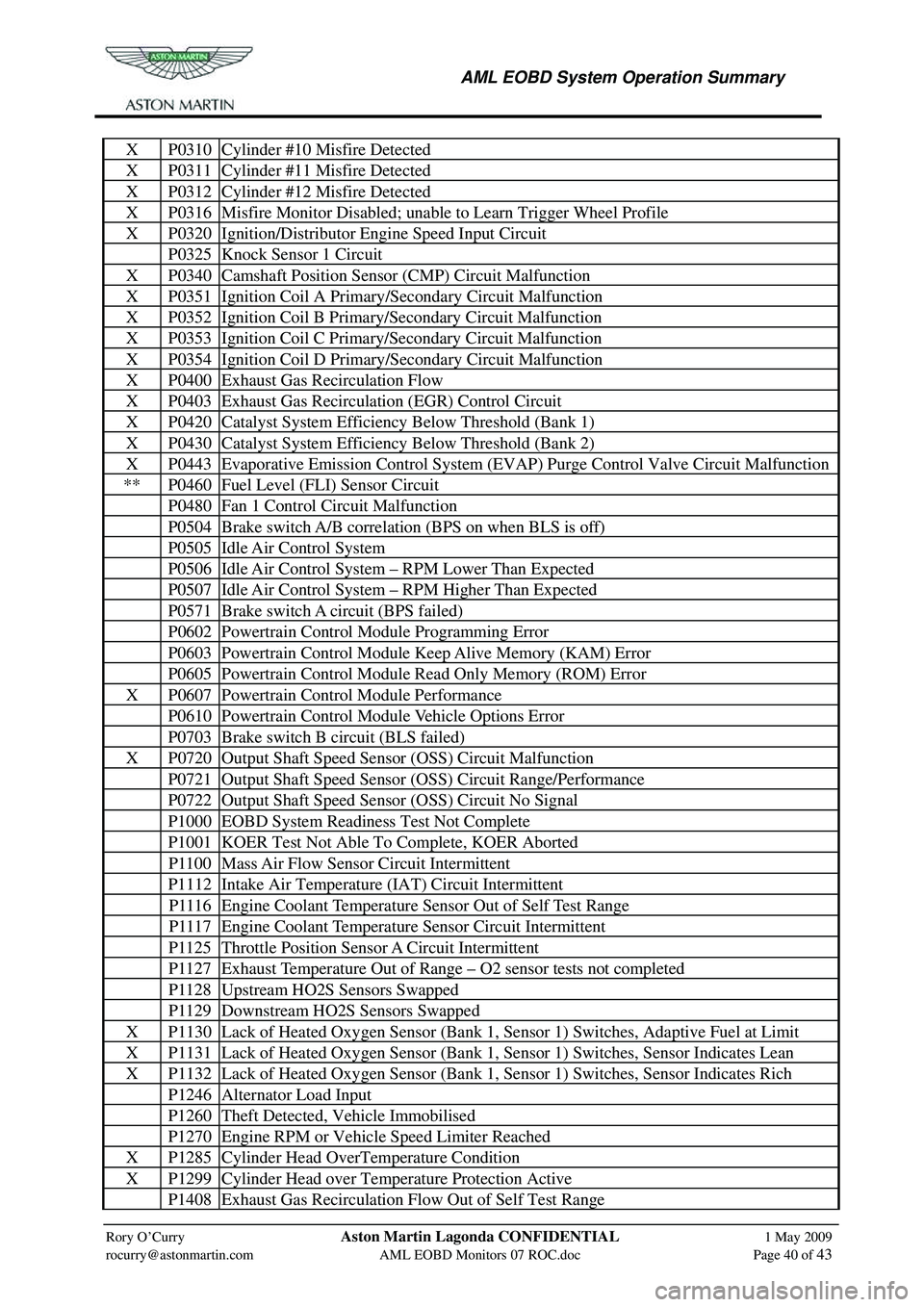
X P0310 Cylinder #10 Misfire Detected
X P0311 Cylinder #11 Misfire Detected
X P0312 Cylinder #12 Misfire Detected
X P0316 Misfire Monitor Disabled; unable to Learn Trigger Wheel Profile
X P0320 Ignition/Distributor Engine Speed Input Circuit
P0325 Knock Sensor 1 Circuit
X P0340 Camshaft Position Sens or (CMP) Circuit Malfunction
X P0351 Ignition Coil A Primary/Secondary Circuit Malfunction
X P0352 Ignition Coil B Primary/Secondary Circuit Malfunction
X P0353 Ignition Coil C Primary/Secondary Circuit Malfunction
X P0354 Ignition Coil D Primary/Secondary Circuit Malfunction
X P0400 Exhaust Gas Recirculation Flow
X P0403 Exhaust Gas Recirculation (EGR) Control Circuit
X P0420 Catalyst System Efficiency Below Threshold (Bank 1)
X P0430 Catalyst System Efficiency Below Threshold (Bank 2)
X P0443 Evaporative Emission Control System (EVAP) Purge Control Valve Circuit Malfunction
** P0460 Fuel Level (FLI) Sensor Circuit
P0480 Fan 1 Control Circuit Malfunction
P0504 Brake switch A/B correlation (BPS on when BLS is off)
P0505 Idle Air Control System
P0506 Idle Air Control System – RPM Lower Than Expected
P0507 Idle Air Control System – RPM Higher Than Expected
P0571 Brake switch A circuit (BPS failed)
P0602 Powertrain Control Module Programming Error
P0603 Powertrain Control Module Keep Alive Memory (KAM) Error
P0605 Powertrain Control Module Read Only Memory (ROM) Error
X P0607 Powertrain Control Module Performance
P0610 Powertrain Control Module Vehicle Options Error
P0703 Brake switch B circuit (BLS failed)
X P0720 Output Shaft Speed Sensor (OSS) Circuit Malfunction
P0721 Output Shaft Speed Sensor (OSS) Circuit Range/Performance
P0722 Output Shaft Speed Sensor (OSS) Circuit No Signal
P1000 EOBD System Readiness Test Not Complete
P1001 KOER Test Not Able To Complete, KOER Aborted
P1100 Mass Air Flow Sensor Circuit Intermittent
P1112 Intake Air Temperature (IAT) Circuit Intermittent
P1116 Engine Coolant Temperature Sensor Out of Self Test Range
P1117 Engine Coolant Temperature Sensor Circuit Intermittent
P1125 Throttle Position Sensor A Circuit Intermittent
P1127 Exhaust Temperature Out of Range – O2 sensor tests not completed
P1128 Upstream HO2S Sensors Swapped
P1129 Downstream HO2S Sensors Swapped
X P1130 Lack of Heated Oxygen Sensor (Bank 1, Sensor 1) Switches, Adaptive Fuel at Limit
X P1131 Lack of Heated Oxygen Sensor (Bank 1, Sensor 1) Switches, Sensor Indicates Lean
X P1132 Lack of Heated Oxygen Sensor (Bank 1, Sensor 1) Switches, Sensor Indicates Rich
P1246 Alternator Load Input
P1260 Theft Detected, Vehicle Immobilised
P1270 Engine RPM or Vehicle Speed Limiter Reached
X P1285 Cylinder Head OverTemperature Condition
X P1299 Cylinder Head over Temperature Protection Active
P1408 Exhaust Gas Recirculation Flow Out of Self Test Range
Page 886 of 947

AML EOBD System Operation Summary
Rory O’Curry Aston Martin Lagonda CONFIDENTIAL 1 May 2009
[email protected] AML EOBD Monitors 07 ROC.doc Page 41 of 43
X P1431 Misfire Monitor Disabled; unable to Learn Trigger Wheel Profile
P1432 Thermostat Heater Control Circuit
P1460 Wide Open Throttle A/C Cut-out Circuit
P1461 A/C Pressure Sensor Circuit High Input
P1462 A/C Pressure Sensor Circuit Low Input
P1463 A/C Pressure Sensor Insufficient Pressure Change
P1464 A/C Demand Out of Self Test Range
P1500 Vehicle Speed Sensor
P1501 Vehicle Speed Sensor Out of Self Test Range
P1549 Intake Manifold Communica tion Control Circuit (Bank 1)
P1572 Brake system input failure (BLS failed then BPS failed)
P1610 Interactive Reprogramming Code – Replace Module
P1611 Interactive Reprogramming Code – Diagnose Further
P1615 Interactive Reprogramming Code – Erase Error
P1616 Interactive Reprogramming Code – Erase Error, Low Voltage
P1617 Interactive Reprogramming Code – Block Program Error
P1618 Interactive Reprogramming Code – Block Program Error, Low Voltage
P1631 Main Relay (Power Hold)
X P1633 Keep Alive Power Voltage too Low
P1635 Tyre/Axle Out of Acceptable Range
P1639 Vehicle Identification (VID) Block Corrupted. Not Programmed
X P1656 CAN Link PCM/PCM Circuit/Network
P1703 Brake switch out of self test range
P1709 Park/Neutral Position Switch Out of Self Test Range
X P2008 Intake Manifold Runner Control Open (Bank 1)
X P2100 Throttle Actuator Control Motor Circuit Open
X P2101 Throttle Actuator Control Motor Circuit Range/Performance
X P2107 Throttle actuator control motor processor
X P2110 Forced limit RPM mode
X P2111 Throttle actuator control system – stuck closed
X P2112 Throttle actuator control system – stuck open
P2121 Pedal position sensor D circuit range/performance
P2122 Pedal position sensor D circuit low input
P2123 Pedal position sensor D circuit high input
P2124 Pedal position sensor D circuit intermittent
P2126 Pedal position sensor E circuit range/performance
P2127 Pedal position sensor E circuit low input
P2128 Pedal position sensor E circuit high input
P2129 Pedal position sensor E circuit intermittent
P2135 Throttle position sensor A/B voltage correlation
P2138 Pedal position sensor D/E voltage correlation
X P2195 Lack of Heated Oxygen Sensor (Bank 1, Sensor 1) Switches, Sensor Indicates Lean
X P2196 Lack of Heated Oxygen Sensor (Bank 2, Sensor 1) Switches, Sensor Indicates Lean
X P2197 Lack of Heated Oxygen Sensor (Bank 1, Sensor 1) Switches, Sensor Indicates Rich
X P2198 Lack of Heated Oxygen Sensor (Bank 2, Sensor 1) Switches, Sensor Indicates Rich
Note.
X MIL codes
* Can be non-mil if below EOBD threshold.
Page 909 of 947
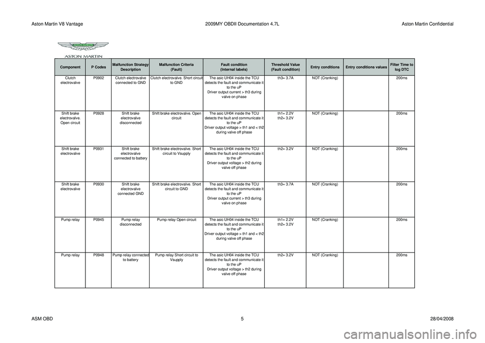
Aston Martin V8 Vantage2009MY OBDII Documentation 4.7L Aston Martin Confidential
Component P CodesMalfunction Strategy
Description Malfunction Criteria
(Fault) Fault condition
(Internal labels) Threshold Value
(Fault condition) Entry conditions Entry conditions values Filter Time to
log DTCClutch
electrovalve P0902 Clutch electrovalve
connected to GND Clutch electrovalve. Short circuit
to GND The asic UH04 inside the TCU
detects the fault and communicate it to the uP
Driver output current > th3 during valve on phase th3= 3.7A
NOT (Cranking) 200ms
Shift brake
electrovalve. Open circuit P0928 Shift brake
electrovalve
disconnected Shift brake electrovalve. Open
circuit The asic UH04 inside the TCU
detects the fault and communicate it to the uP
Driver output voltage > th1 and < th2 during valve off phase th1= 2.2V
th2= 3.2V
NOT (Cranking)
200ms
Shift brake
electrovalve P0931 Shift brake
electrovalve
connected to battery Shift brake electrovalve. Short
circuit to Vsupply The asic UH04 inside the TCU
detects the fault and communicate it to the uP
Driver output voltage > th2 during valve off phase th2= 3.2V
NOT (Cranking) 200ms
Shift brake
electrovalve P0930 Shift brake
electrovalve
connected GND Shift brake electrovalve. Short
circuit to GND The asic UH04 inside the TCU
detects the fault and communicate it to the uP
Driver output current > th3 during valve on phase th3= 3.7A
NOT (Cranking) 200ms
Pump relay P0945 Pump relay disconnectedPump relay Open circuit The asic UH04 inside the TCU
detects the fault and communicate it to the uP
Driver output voltage > th1 and < th2 during valve off phase th1= 2.2V
th2= 3.2V
NOT (Cranking)
200ms
Pump relay P0948 Pump relay connected to batteryPump relay Short circuit to
Vsupply The asic UH04 inside the TCU
detects the fault and communicate it to the uP
Driver output voltage > th2 during valve off phase th2= 3.2V
NOT (Cranking) 200ms
ASM OBD 528/04/2008