weight ASTON MARTIN V8 VANTAGE 2010 Workshop Manual
[x] Cancel search | Manufacturer: ASTON MARTIN, Model Year: 2010, Model line: V8 VANTAGE, Model: ASTON MARTIN V8 VANTAGE 2010Pages: 947, PDF Size: 43.21 MB
Page 31 of 947
Body Closures (01.03)
Body System (01.00)
May 2007 Workshop Manual 1-3-5
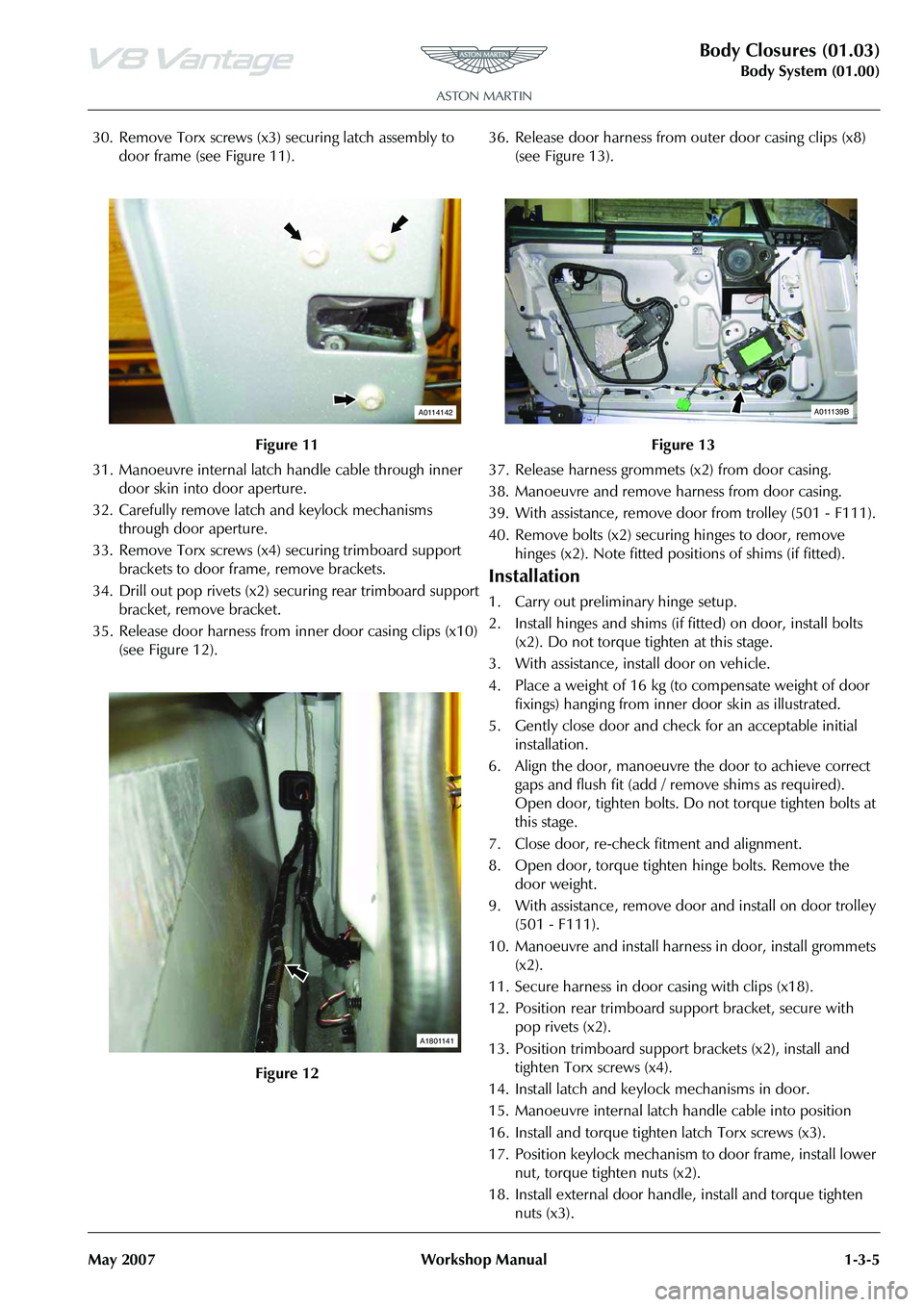
30. Remove Torx screws (x3) securing latch assembly to
door frame (see Figure 11).
31. Manoeuvre internal latch handle cable through inner door skin into door aperture.
32. Carefully remove latch and keylock mechanisms through door aperture.
33. Remove Torx screws (x4) securing trimboard support
brackets to door frame, remove brackets.
34. Drill out pop rivets (x2) securing rear trimboard support bracket, remove bracket.
35. Release door harness from inner door casing clips (x10) (see Figure 12). 36. Release door harness from outer door casing clips (x8)
(see Figure 13).
37. Release harness grommets (x2) from door casing.
38. Manoeuvre and remove ha rness from door casing.
39. With assistance, remove door from trolley (501 - F111).
40. Remove bolts (x2) securing hinges to door, remove
hinges (x2). Note fitted posi tions of shims (if fitted).
Installation
1. Carry out preliminary hinge setup.
2. Install hinges and shims (if fitted) on door, install bolts
(x2). Do not torque tighten at this stage.
3. With assistance, install door on vehicle.
4. Place a weight of 16 kg (to compensate weight of door fixings) hanging from inner door skin as illustrated.
5. Gently close door and check for an acceptable initial installation.
6. Align the door, manoeuvre the door to achieve correct gaps and flush fit (add / remove shims as required).
Open door, tighten bolts. Do not torque tighten bolts at
this stage.
7. Close door, re-check fitment and alignment.
8. Open door, torque tighten hinge bolts. Remove the door weight.
9. With assistance, remove door and install on door trolley
(501 - F111).
10. Manoeuvre and install harness in door, install grommets (x2).
11. Secure harness in door casing with clips (x18).
12. Position rear trimboard support bracket, secure with pop rivets (x2).
13. Position trimboard support brackets (x2), install and
tighten Torx screws (x4).
14. Install latch and keylock mechanisms in door.
15. Manoeuvre internal latch handle cable into position
16. Install and torque tighten latch Torx screws (x3).
17. Position keylock mechanism to door frame, install lower nut, torque tighten nuts (x2).
18. Install external door handle, install and torque tighten nuts (x3).
Figure 11
Figure 12
A0114142
A1801141
Figure 13
A011139B
Page 140 of 947
Convertible Roof (01.17)
Body System (01.00)1-12-2 Workshop Manual May 2007
Maintenance
Hood Assembly-Renew
Removal
1. Remove Tonneau well liner (see Workshop Manual procedure 01.17.DB Tonneau Well Liner - Renew).
2. Remove Panel assembly body side LH (see Workshop
Manual procedure 01.05.DY Panel Assembly - Bodyside
Trim - Rear - LH - Renew).
3. Remove Panel assembly body side RH (see Workshop Manual procedure 01.05.DX Panel Assembly - Bodyside
Trim - Rear - RH - Renew).
4. Remove Tonneau cover (see Workshop Manual procedure 01.17.CA Cover - Tonneau - Renew).
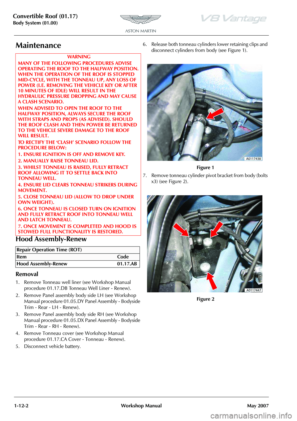
5. Disconnect vehicle battery. 6. Release both tonneau cylinders lower retaining clips and
disconnect cylinders from body (see Figure 1).
7. Remove tonneau cylinder pivot bracket from body (bolts x3) (see Figure 2).
WAR NI NG
MANY OF THE FOLLOWING PROCEDURES ADVISE
OPERATING THE ROOF TO THE HALFWAY POSITION.
WHEN THE OPERATION OF THE ROOF IS STOPPED
MID-CYCLE, WITH THE TO NNEAU UP, ANY LOSS OF
POWER (I.E. REMOVING THE VEHICLE KEY OR AFTER
10 MINUTES OF IDLE) WILL RESULT IN THE
HYDRAULIC PRESSURE DROPPING AND MAY CAUSE
A CLASH SCENARIO.
WHEN ADVISED TO OPEN THE ROOF TO THE
HALFWAY POSITION, ALWA YS SECURE THE ROOF
WITH STRAPS AND PROPS (AS ADVISED). SHOULD
THE ROOF CLASH AND THEN POWER BE RETURNED
TO THE VEHICLE SEVERE DAMAGE TO THE ROOF
WILL RESULT.
TO RECTIFY THE ‘CLASH’ SCENARIO FOLLOW THE
PROCEDURE BELOW:
1. ENSURE IGNITION IS OFF AND REMOVE KEY.
2. MANUALLY RAISE TONNEAU LID.
3. WHILST TONNEAU IS RAISED, FULLY RETRACT
ROOF ALLOWING IT TO SETTLE BACK INTO
TONNEAU WELL.
4. ENSURE LID CLEARS TONNEAU STRIKERS DURING
MOVEMENT.
5. CLOSE TONNEAU LID (ALLOW TO DROP UNDER
OWN WEIGHT).
6. ONCE TONNEAU IS CLOSED TURN ON IGNITION
AND FULLY RETRACT ROOF INTO TONNEAU WELL
AND LATCH TONNEAU.
7. ONCE MOVEMENT IS COMPLETED AND HOOD IS
STOWED FULL FUNCTIONALITY IS RESTORED.
Repair Operation Time (ROT)
Figure 1
Figure 2
Page 143 of 947
Convertible Roof (01.17)
Body System (01.00)
May 2007 Workshop Manual 1-12-5
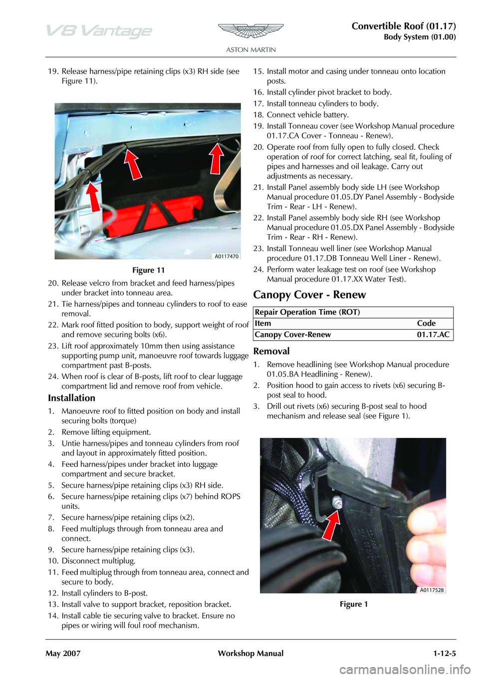
19. Release harness/pipe retaining clips (x3) RH side (see Figure 11).
20. Release velcro from bracket and feed harness/pipes under bracket into tonneau area.
21. Tie harness/pipes and tonneau cylinders to roof to ease removal.
22. Mark roof fitted position to body, support weight of roof and remove securing bolts (x6).
23. Lift roof approximately 10mm then using assistance
supporting pump unit, manoeuvre roof towards luggage
compartment past B-posts.
24. When roof is clear of B-post s, lift roof to clear luggage
compartment lid and remove roof from vehicle.
Installation
1. Manoeuvre roof to fitted position on body and install securing bolts (torque)
2. Remove lifting equipment.
3. Untie harness/pipes and tonneau cylinders from roof and layout in approximately fitted position.
4. Feed harness/pipes under bracket into luggage compartment and secure bracket.
5. Secure harness/pipe retaining clips (x3) RH side.
6. Secure harness/pipe retaining clips (x7) behind ROPS units.
7. Secure harness/pipe retaining clips (x2).
8. Feed multiplugs through from tonneau area and connect.
9. Secure harness/pipe retaining clips (x3).
10. Disconnect multiplug.
11. Feed multiplug through from tonneau area, connect and secure to body.
12. Install cylinders to B-post.
13. Install valve to support bracket, reposition bracket.
14. Install cable tie securing valve to bracket. Ensure no pipes or wiring will foul roof mechanism. 15. Install motor and casing under tonneau onto location
posts.
16. Install cylinder pivot bracket to body.
17. Install tonneau cylinders to body.
18. Connect vehicle battery.
19. Install Tonneau cover (see Workshop Manual procedure 01.17.CA Cover - Tonneau - Renew).
20. Operate roof from fully open to fully closed. Check operation of roof for correct latching, seal fit, fouling of
pipes and harnesses and oil leakage. Carry out
adjustments as necessary.
21. Install Panel assembly bo dy side LH (see Workshop
Manual procedure 01.05.DY Panel Assembly - Bodyside
Trim - Rear - LH - Renew).
22. Install Panel assembly body side RH (see Workshop Manual procedure 01.05.DX Pa nel Assembly - Bodyside
Trim - Rear - RH - Renew).
23. Install Tonneau well line r (see Workshop Manual
procedure 01.17.DB Tonneau Well Liner - Renew).
24. Perform water leakage test on roof (see Workshop Manual procedure 01.17.XX Water Test).
Canopy Cover - Renew
Removal
1. Remove headlining (see Workshop Manual procedure
01.05.BA Headlining - Renew).
2. Position hood to gain access to rivets (x6) securing B- post seal to hood.
3. Drill out rivets (x6) secu ring B-post seal to hood
mechanism and release seal (see Figure 1).
Figure 11
Repair Operation Time (ROT)
Page 214 of 947
Restraining Devices (01.20)
Body System (01.00)1-14-2 Workshop Manual May 2007
mounted onto a spindle (torsion bar) which once the sensor
has locked the retractor reel and a predetermined load is
applied, twists and allows additional webbing into the
system. The deceleration force required to initiate this
sequence is approximately th e same as that required to
initiate airbag deployment. The torsion bar load limiting
device will only react if the safety belt is in use at the time of
the impact.
Emergency Locking Retractor (ELR)
The retractors in all seat posi tions feature ELR. During any
period of sudden deceleration, or under lateral load when
cornering at speed, a sensor weight within the safety belt
retractor moves a locking pawl against the teeth on the
retractor reel, which then locks the retractor preventing any
further release of webbing. As soon as the load applied onto
the retractor through the safety belt webbing is removed the
locking pawl releases the retractor reel and normal
movement is returned to the retractor.
Automatic Locking Retractor (ALR)
Automatic locking retractors (ALR) are installed to all
passenger seat positions.
The safety belt webbing on these are clearly marked to show
their operating feature. To initiate the ALR system, fasten the
safety belt into it’s buckle and pull all of the webbing from
the retractor, as the safety belt is released the retractor locks
allowing travel in only one plane thus producing a fixed
length restraint and preventing the safety belt from
introducing slack, making any child seat it may be restraining
secure. The ALR system of the retractor is disengaged by
releasing the safety belt and allowing the safety belt to fully
retract onto the reel. Caution
It should be considered th at during any event that
utilizes the full capability of the safety belts, the
webbing may have been elongated and the torsion bar may have twisted. For this reason, if a vehicle is
involved in an accident which results in the deployment of the airbag(s), all the safety belts that were in use at
the time of the accident MUST be renewed.
Page 229 of 947
Subframes (02.03)
Frame and Mounting (02.00)
May 2007 Workshop Manual 2-1-7
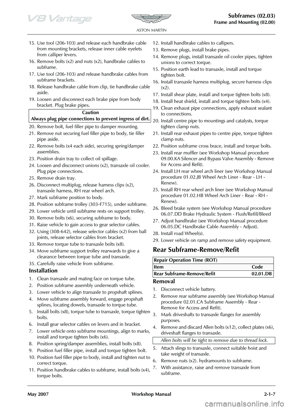
15. Use tool (206-103) and release each handbrake cable from mounting brackets, re lease inner cable eyelets
from calliper levers.
16. Remove bolts (x2) and nuts (x2), handbrake cables to subframe.
17. Use tool (206-103) and release handbrake cables from subframe brackets.
18. Release handbrake cable from clip, tie handbrake cable aside.
19. Loosen and disconnect each brake pipe from body bracket. Plug brake pipes
.
20. Remove bolt, fuel filler pipe to damper mounting.
21. Remove nut securing fuel fi ller pipe to body, tie filler
pipe aside.
22. Remove bolts (x4 each side), securing spring/damper assemblies.
23. Position drain tray to collect oil spillage.
24. Loosen and disconnect unions (x2), transaxle oil cooler.
Plug pipe connections.
25. Remove drain tray.
26. Disconnect multiplug, release harness clips (x2), transaxle harness, RH rear wheel arch.
27. Mark subframe position to body.
28. Position subframe trolley (303-F715), under subframe.
29. Lower vehicle until subfra me rests on support trolley.
30. Remove bolts (x6), securing subframe to body.
31. Raise vehicle to gain access to gear selector cables.
32. Using (308-642), release se lector cables (x2) from ball
joints, release selector cables from bracket.
33. Remove torque tube to transaxle bolts (x8).
34. Move subframe support trolley rearwards to give a clearance between torque tube and transaxle.
35. Carefully raise vehicle from subframe.
Installation
1. Clean transaxle and mating face on torque tube.
2. Position subframe assembly underneath vehicle.
3. Lower vehicle to align transaxle to propshaft splines.
4. Move subframe assembly forward, engage propshaft splines, locating dowels, transaxle to torque tube.
5. Install bolts (x8), torque tube to transaxle, torque tighten bolts.
6. Install gear selector cables on levers and in bracket.
7. Lower vehicle onto subframe mountings, align to marks, install and torque tighten bolts (x6).
8. Position spring/damper assemblies, install bolts (x8).
9. Position fuel filler pipe, install and torque tighten bolt.
10. Position fuel filler pipe to body, install and tighten nut to correct torque.
11. Position handbrake cables to subframe, install bolts (x4), torque bolts. 12. Install handbrake cables to callipers.
13. Remove plugs, install brake pipes.
14. Remove plugs, install transaxle oil cooler pipes, tighten
unions to correct torque.
15. Position earth lead to transaxle, install and torque tighten bolt.
16. Install transaxle harness multiplug, secure harness clips (x2).
17. Install shear plate, install and torque tighten bolts (x8).
18. Install heat shield, install and torque tighten bolts (x4).
19. Clean exhaust pipe connections, apply exhaust sealant to connections.
20. Install centre pipe to mountings and catalysts, torque tighten clamp nuts.
21. Install rear exhaust pipes to centre pipe, torque tighten clamp nuts.
22. Position subframe cross brace, install and torque bolts.
23. Install rear muffler (see Workshop Manual procedure 09.00.KA Silencer and Bypass Valve Assembly - Remove
for Access and Refit).
24. Install LH rear wheel arch liner (see Workshop Manual procedure 01.02.JB Wheel Arch Liner - Rear - LH -
Renew).
25. Install RH rear wheel arch liner (see Workshop Manual procedure 01.02.HB Wheel Arch Liner - Rear - RH -
Renew).
26. Bleed brake system (see Workshop Manual procedure 06.07.DD Brake Hydraulic System - Flush/Refill/Bleed
27. Adjust handbrake (see Wo rkshop Manual procedure
06.05.DC Handbrake Cable Assembly - Adjust).
28. Install road Wheel(s).
29. Lower vehicle on ramp and remove safety equipment.
Rear Subframe-Remove/Refit
Removal
1. Disconnect vehicle battery.
2. Remove rear subframe asse mbly (see Workshop Manual
procedure 02.01.CA Subframe Assembly - Rear -
Remove for Access and Refit).
3. Mark driveshafts to transaxle flanges for assembly purposes.
4. Remove and discard Allen bolts (x12), collect plates (x6), driveshaft flanges to transaxle.
5. Attach slings to transaxle, connect suitable hoist and
take weight of transaxle.
6. Remove nuts (x2). hydramounts to subframe.
7. With assistance, raise and remove transaxle from subframe.
Caution
Always plug pipe connections to prevent ingress of dirt.
Repair Operation Time (ROT)
Page 275 of 947
Lubrication System (03.02)
Engine (03.00)
Issue 5, Janauary 2010 Workshop Manual 3-2-1
Engine (03.00)
Lubrication System (03.02)
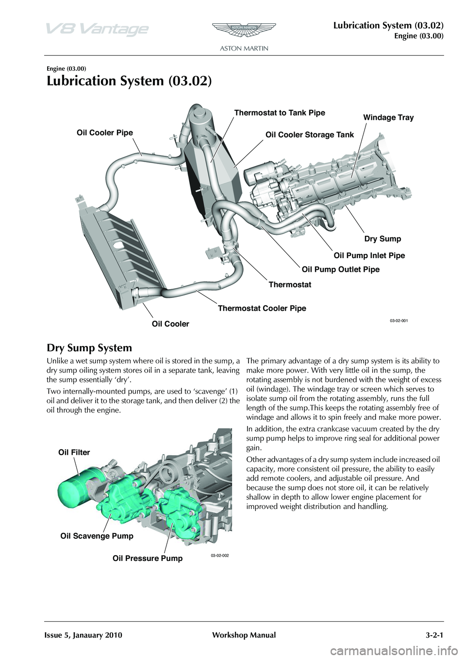
Dry Sump System
Unlike a wet sump system where oil is stored in the sump, a
dry sump oiling system stores oil in a separate tank, leaving
the sump essentially ‘dry’.
Two internally-mounted pumps, are used to ‘scavenge’ (1)
oil and deliver it to the storage tank, and then deliver (2) the
oil through the engine. The primary advantage of a dry sump system is its ability to
make more power. With very little oil in the sump, the
rotating assembly is not burdened with the weight of excess
oil (windage). The windage tray or screen which serves to
isolate sump oil from the rota
ting assembly, runs the full
length of the sump.This keeps the rotating assembly free of
windage and allows it to spin freely and make more power.
In addition, the extra crankcase vacuum created by the dry
sump pump helps to improve ring seal for additional power
gain.
Other advantages of a dry sump system include increased oil
capacity, more consistent oil pr essure, the ability to easily
add remote coolers, and adjustable oil pressure. And
because the sump does not stor e oil, it can be relatively
shallow in depth to allow lower engine placement for
improved weight distribution and handling.
Oil Cooler Oil Cooler Storage Tank
Oil Cooler Pipe
Thermostat
Thermostat to Tank Pipe
Thermostat Cooler Pipe Dry Sump
Oil Pump Outlet Pipe Oil Pump Inlet PipeWindage Tray03-02-001
Oil Filter
Oil Scavenge Pump Oil Pressure Pump
03-02-002
Page 417 of 947
Engine Management System (03.14)
Engine (03.00)
Issue 5, Janauary 2010 Workshop Manual 3-14-1
Engine (03.00)
Engine Management System (03.14)
Maintenance
LH Front Lower Heated Exhaust Gas
Oxygen (HEGO) Sensor - Renew
Removal
1. Raise vehicle on ramp.
2. Remove rear exhaust silencer (refer to Workshop Manual procedure 09.00.KA Silencer and Bypass Valve
Assembly - Remo ve for Access and Refit).
3. Disconnect multiplugs (x2), HEGO sensors.
4. Secure sufficient lengths of string to HEGO sensor multiplugs for assembly purposes.
5. Loosen LH and RH clamp nuts, catalysts to centre pipes.
6. With assistance, manoeuvre exhaust centre pipe assembly rearwards to release from catalysts.
7. Remove nuts (x3), catalyst to exhaust manifold.
8. Release and support weight of LH catalyst from exhaust
manifold.
9. Manoeuvre HEGO sensor leads and remove cable tie. Release HEGO sensor leads from behind heat shield.
Remove string from HEGO multiplugs.
10. Remove catalyst assembly.
11. Remove and discard gasket.
12. Remove HEGO sens ors from catalyst.
Installation
1. Clean catalyst, mating joint faces and HEGO sensors.
2. Install and tighten HEGO sensor to catalyst.
3. Apply proprietary exhaust se alant around clamp joints.
4. Install new gasket to exhaust manifold.
5. Position catalyst, secure string (x2) to HEGO multiplugs, feed sensor leads behind heat shield. Install catalyst to
exhaust manifold.
6. Instal land tighten nuts (x3), catalyst to exhaust manifold.
7. Align centre pipe assembly to catalyst, tighten clamp
nuts.
8. Remove string (x2), conne ct multiplugs (x2), HEGO
sensors.
9. Install rear exhaust silencer (refer to Workshop Manual procedure 09.00.KA Silencer and Bypass Valve
Assembly - Remo ve for Access and Refit).
10. Lower vehicle on ramp.
LH Front Upper Heated Exhaust Gas
Oxygen (HEGO) Sensor - Renew
Repair Operation Time (ROT)
Repair Operation Time (ROT)
WA R N I N G
THE EXHAUST SYSTEM WILL BE VERY HOT AFTER OPERATION. LET THE EXHAUST SYSTEM COOL
BEFORE YOU DO WORK. IF YOU DO NOT, SEVERE
INJURY CAN OCCUR.
Repair Operation Time (ROT)
Page 418 of 947
Engine Management System (03.14)
Engine (03.00)3-14-2 Workshop Manual Issue 5, Janauary 2010
Removal
1. Raise vehicle on ramp.
2. Remove rear exhaust silencer (refer to Workshop Manual procedure 09.00.KA Silencer and Bypass Valve
Assembly - Remove for Access and Refit).
3. Disconnect multiplugs (x2), HEGO sensors.
4. Secure sufficient lengths of string to HEGO sensor multiplugs for assembly purposes.
5. Loosen LH and RH clamp nuts, catalysts to centre pipes.
6. With assistance, manoeuvre exhaust centre pipe assembly rearwards to release from catalysts.
7. Remove nuts (x3), catalyst to exhaust manifold.
8. Release and support weight of LH catalyst from exhaust manifold.
9. Manoeuvre HEGO sensor leads and remove cable tie. Release HEGO sensor leads from behind heat shield.
Remove string from HEGO multiplugs.
10. Remove catalyst assembly.
11. Remove and discard gasket.
12. Remove HEGO sensors from catalyst.
Installation
1. Clean catalyst, mating joint faces and HEGO sensors.
2. Install and tighten HEGO sensor to catalyst.
3. Apply proprietary exhaust sealant around clamp joints.
4. Install new gasket to exhaust manifold.
5. Position catalyst, secure string (x2) to HEGO multiplugs, feed sensor leads behind heat shield. Install catalyst to
exhaust manifold.
6. Instal land tighten nuts (x3), catalyst to exhaust manifold.
7. Align centre pipe assembly to catalyst, tighten clamp nuts to.
8. Remove string (x2), connect multiplugs (x2), HEGO sensors.
9. Install rear exhaust silencer (refer to Workshop Manual
procedure 09.00.KA Silencer and Bypass Valve
Assembly - Remove for Access and Refit).
10. Lower vehicle on ramp.
RH Front Upper Heated Exhaust Gas
Oxygen (HEGO) Sensor - Renew
Removal
1. Raise vehicle on ramp.
2. Remove rear exhaust silencer (refer to Workshop Manual procedure 09.00.KA Silencer and Bypass Valve
Assembly - Remove for Access and Refit).
3. Disconnect multiplugs (x2), HEGO sensors.
4. Secure sufficient lengths of string to HEGO sensor
multiplugs for assembly purposes.
5. Loosen LH and RH clamp nuts, catalysts to centre pipes.
6. With assistance, manoeuvre exhaust centre pipe assembly rearwards to release from catalysts.
7. Remove nuts (x3), catalyst to exhaust manifold.
8. Release and support weight of LH catalyst from exhaust
manifold.
9. Manoeuvre HEGO sensor leads and remove cable tie. Release HEGO sensor leads from behind heat shield.
Remove string from HEGO multiplugs.
10. Remove catalyst assembly.
11. Remove and discard gasket.
12. Remove HEGO sensors from catalyst.
Installation
1. Clean catalyst, mating joint faces and HEGO sensors.
2. Install and tighten HEGO sensor to catalyst.
3. Apply proprietary exhaust sealant around clamp joints.
4. Install new gasket to exhaust manifold.
5. Position catalyst, secure string (x2) to HEGO multiplugs, feed sensor leads behind heat shield. Install catalyst to
exhaust manifold.
6. Instal land tighten nuts (x3), catalyst to exhaust manifold.
7. Align centre pipe assembly to catalyst, tighten clamp nuts to.
8. Remove string (x2), connect multiplugs (x2), HEGO sensors.
9. Install rear exhaust silencer (refer to Workshop Manual procedure 09.00.KA Silencer and Bypass Valve
Assembly - Remove for Access and Refit).
10. Lower vehicle on ramp.
RH Rear Lower Heated Exhaust Gas
Oxygen (HEGO) Sensor - Renew
WAR NI NG
THE EXHAUST SYSTEM WILL BE VERY HOT AFTER OPERATION. LET THE EXHAUST SYSTEM COOL
BEFORE YOU DO WORK. IF YOU DO NOT, SEVERE INJURY CAN OCCUR.
Repair Operation Time (ROT)
WAR NI NG
THE EXHAUST SYSTEM WILL BE VERY HOT AFTER OPERATION. LET THE EXHAUST SYSTEM COOL
BEFORE YOU DO WORK. IF YOU DO NOT, SEVERE INJURY CAN OCCUR
Repair Operation Time (ROT)
ItemCode
Rear Lower Heated Exhaust Gas
Oxygen (HEGO) Sensor - Renew 03.14.JB
Page 419 of 947
Engine Management System (03.14)
Engine (03.00)
Issue 5, Janauary 2010 Workshop Manual 3-14-3
Removal
1. Raise vehicle on ramp.
2. Remove rear exhaust silencer (refer to Workshop Manual procedure 09.00.KA Silencer and Bypass Valve
Assembly - Remove for Access and Refit).
3. Disconnect multiplugs (x2), HEGO sensors.
4. Secure sufficient lengths of string to HEGO sensor multiplugs for assembly purposes.
5. Loosen LH and RH clamp nuts, catalysts to centre pipes.
6. With assistance, manoeuvre exhaust centre pipe assembly rearwards to release from catalysts.
7. Remove nuts (x3), catalyst to exhaust manifold.
8. Release and support weight of LH catalyst from exhaust manifold.
9. Manoeuvre HEGO sensor leads and remove cable tie. Release HEGO sensor leads from behind heat shield.
Remove string from HEGO multiplugs.
10. Remove catalyst assembly.
11. Remove and discard gasket.
12. Remove HEGO sensors from catalyst.
Installation
1. Clean catalyst, mating joint faces and HEGO sensors.
2. Install and tighten HEGO sensor to catalyst.
3. Apply proprietary exhaust se alant around clamp joints.
4. Install new gasket to exhaust manifold.
5. Position catalyst, secure string (x2) to HEGO multiplugs, feed sensor leads behind heat shield. Install catalyst to
exhaust manifold.
6. Instal land tighten nuts (x3), catalyst to exhaust manifold.
7. Align centre pipe assembly to catalyst, tighten clamp
nuts to.
8. Remove string (x2), conne ct multiplugs (x2), HEGO
sensors.
9. Install rear exhaust silencer (refer to Workshop Manual procedure 09.00.KA Silencer and Bypass Valve
Assembly - Remove for Access and Refit).
10. Lower vehicle on ramp.
Left Side Powertrain Control Module
(PCM) (Coupe Only) - Remove and
Install
Remove
1. Disconnect the ba ttery ground cable.
2. Remove the wheel and tyre. (refer to Workshop Manual procedure 04.04.EC - Wheel and Tyre)
3. Remove the six rear screws that attach the wheel-arch liner to the body.
4. Remove the rear screw that attaches the wheel-arch liner to the body.
5. Turn the steering fully to the right.
6. Move the wheel arch liner to get access to the Powertrain Control Module (PCM).
7. Disconnect the electrical connector from the direction
indicator.
8. Release the four fi r-tree clips that attach the wiring
harness for the direction indi cator and the screen wash
system.
9. Release the two fir tree clips that attach the wiring harness for the PCM.
10. Remove the three bolts that attach the PCM bottom bracket and PCM to the PCM top bracket.
11. Disconnect the three electrical connectors from the PCM.
12. Remove the PCM.
Install
1. Put the PCM in position.
2. Connect the three electrical connectors to the PCM.
3. Align the PCM to the top bracket.
4. Align the bottom bracket to the PCM.
5. Install and tighten the three bolts that attach the PCM bottom bracket and PCM to the PCM top bracket.
6. Install the two fir tree clips that attach the wiring harness for the PCM.
7. Attach the four fir-tree cl ips that attach the wiring
harness for the direction indi cator and the screen wash
system.
8. Connect the electrical connector to the direction indicator.
9. Put the wheel-arch liner into the correct position.
10. Install and tighten the rear screw that attaches the wheel-arch liner to the body.
11. Install and tighten the six rear screws that attach the wheel-arch liner to the body.
12. Move the steering to the centre position.
13. Connect the battery ground cable.
14. Install the wheel and tyre. (04.04.EC - Wheel and Tyre)
15. Connect AMDS.
16. Use AMDS to do a test of the PCM. (00.06.AD - AMDS Operation Check)
WA R N I N G
THE EXHAUST SYSTEM WILL BE VERY HOT AFTER OPERATION. LET THE EXHAUST SYSTEM COOL
BEFORE YOU DO WORK. IF YOU DO NOT, SEVERE
INJURY CAN OCCUR
Repair Operation Time (ROT)
Page 451 of 947
Road Wheels and Tyres (04.04)
Suspension (04.00)
May 2007 Workshop Manual 4-4-1
Suspension (04.00)
Road Wheels and Tyres (04.04)Specifications
Tyres
The tyres recommended by Aston Martin meet the high
speed performance of this vehi cle. Only tyres of identical
specification may be installed as replacements. Under no
circumstances must cross-ply tyres be installed.
Unique Aston Martin lightweight aluminium alloy road
wheels. The tyres are made exclusively for Aston Martin.
Standard
Wheels
• Front - 8.5J x 18
• Rear - 9.5J x 18
Tyres
• Front - Bridgestone 235/40 ZR 18 (94Y)
Rear - Bridgestone 275/35 ZR 18 (99Y)
Optional
Wheels
• Front - 8.5J x 19
• Rear - 9.5J x 19
Tyres
• Front - Bridgestone 235/40 ZR 19 (92Y)