wheel torque ASTON MARTIN V8 VANTAGE 2010 Workshop Manual
[x] Cancel search | Manufacturer: ASTON MARTIN, Model Year: 2010, Model line: V8 VANTAGE, Model: ASTON MARTIN V8 VANTAGE 2010Pages: 947, PDF Size: 43.21 MB
Page 753 of 947

Torque Figures
Appendix & Glossary20-1-14 Workshop Manual May 2007
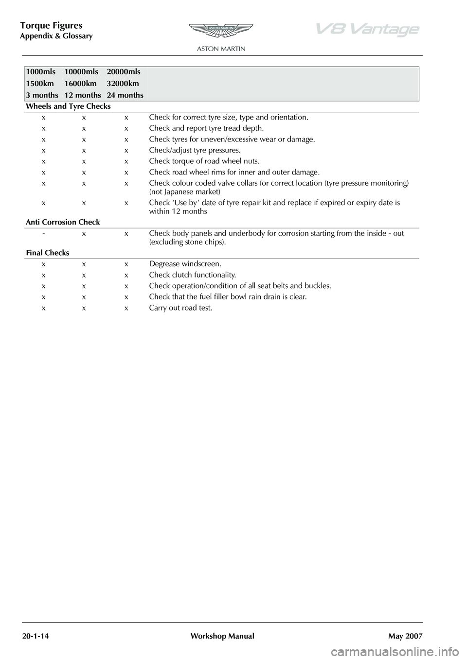
Wheels and Tyre Checks
x x x Check for correct tyre size, type and orientation.
x x x Check and report tyre tread depth.
x x x Check tyres for uneven/excessive wear or damage.
x x x Check/adjust tyre pressures.
x x x Check torque of road wheel nuts.
x x x Check road wheel rims for inner and outer damage.
x x x Check colour coded valve collars for co rrect location (tyre pressure monitoring)
(not Japanese market)
x x x Check ‘Use by ’ date of tyre repair kit and replace if expired or expiry date is
within 12 months
Anti Corrosion Check - x x Check body panels and underbody for corrosion starting from the inside - out
(excluding stone chips).
Final Checks x x x Degrease windscreen.
x x x Check clutch functionality.
x x x Check operation/condition of all seat belts and buckles.
x x x Check that the fuel filler bowl rain drain is clear.
x x x Carry out road test.
1000mls
1500km
3 months10000mls
16000km
12 months20000mls
32000km
24 months
Page 792 of 947

Squeaks and Rattles Repair Manual
Page 8 of 21 Issue 3
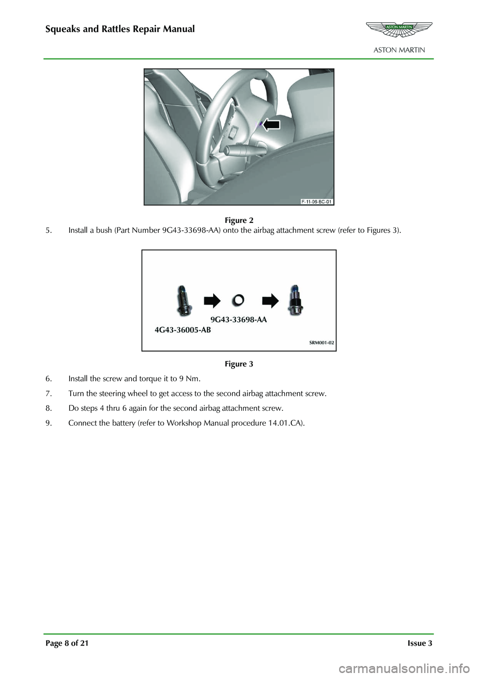
Figure 2
5. Install a bush (Part Number 9G43-33698-AA) onto th e airbag attachment screw (refer to Figures 3).
Figure 3
6. Install the screw and torque it to 9 Nm.
7. Turn the steering wheel to get access to the second airbag attachment screw.
8. Do steps 4 thru 6 again for the second airbag attachment screw.
9. Connect the battery (refer to Work shop Manual procedure 14.01.CA).
Page 883 of 947

AML EOBD System Operation Summary
Rory O’Curry Aston Martin Lagonda CONFIDENTIAL 1 May 2009
[email protected] AML EOBD Monitors 07 ROC.doc Page 37 of 43
Glossary of Terms
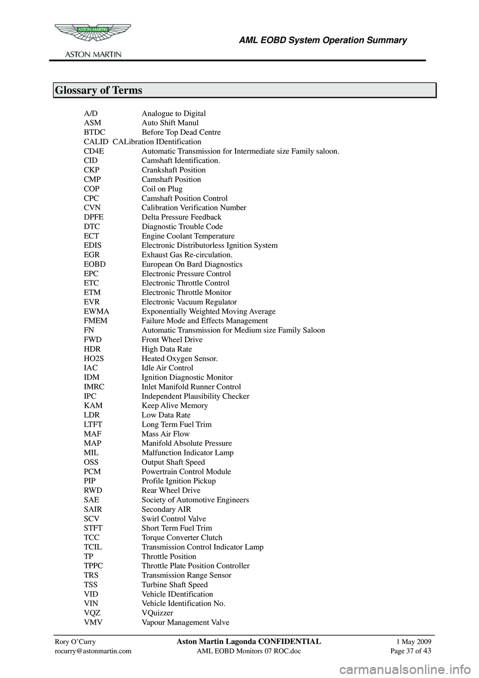
A/D Analogue to Digital
ASM Auto Shift Manul
BTDC Before Top Dead Centre
CALID CALibration IDentification
CD4E Automatic Transmission for Intermediate size Family saloon.
CID Camshaft Identification.
CKP Crankshaft Position
CMP Camshaft Position
COP Coil on Plug
CPC Camshaft Position Control
CVN Calibration Verification Number
DPFE Delta Pressure Feedback
DTC Diagnostic Trouble Code
ECT Engine Coolant Temperature
EDIS Electronic Distributorless Ignition System
EGR Exhaust Gas Re-circulation.
EOBD European On Bard Diagnostics
EPC Electronic Pressure Control
ETC Electronic Throttle Control
ETM Electronic Throttle Monitor
EVR Electronic Vacuum Regulator
EWMA Exponentially Weighted Moving Average
FMEM Failure Mode and Effects Management
FN Automatic Transmission for Medium size Family Saloon
FWD Front Wheel Drive
HDR High Data Rate
HO2S Heated Oxygen Sensor.
IAC Idle Air Control
IDM Ignition Diagnostic Monitor
IMRC Inlet Manifold Runner Control
IPC Independent Plausibility Checker
KAM Keep Alive Memory
LDR Low Data Rate
LTFT Long Term Fuel Trim
MAF Mass Air Flow
MAP Manifold Absolute Pressure
MIL Malfunction Indicator Lamp
OSS Output Shaft Speed
PCM Powertrain Control Module
PIP Profile Ignition Pickup
RWD Rear Wheel Drive
SAE Society of Automotive Engineers
SAIR Secondary AIR
SCV Swirl Control Valve
STFT Short Term Fuel Trim
TCC Torque Converter Clutch
TCIL Transmission Control Indicator Lamp
TP Throttle Position
TPPC Throttle Plate Position Controller
TRS Transmission Range Sensor
TSS Turbine Shaft Speed
VID Vehicle IDentification
VIN Vehicle Identification No.
VQZ VQuizzer
VMV Vapour Management Valve
Page 933 of 947

System
Component
P Codes (AML)
Malfunction Strategy Description
Malfunction Criteria
(Fault)
Fault condition
(Internal labels)
Threshold Value
(Fault condition)
Entry conditions
Entry conditions values
Filter Time to log DTC (AML)
EMS controlled MIL Illumination
(AML)
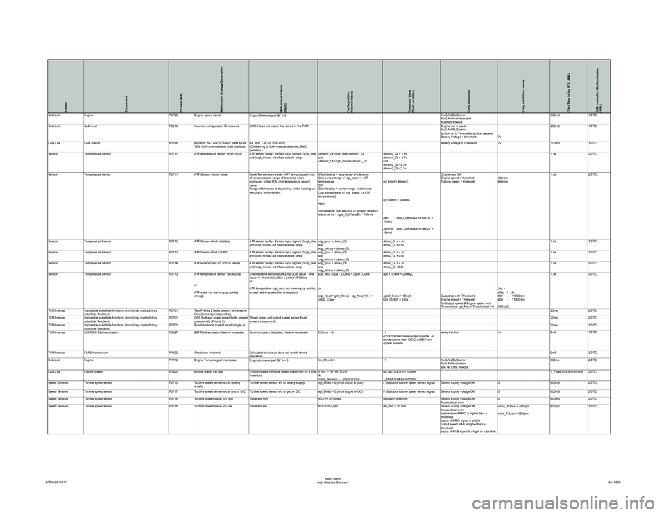
CAN LinkEngine P0725Engine speed signal
Engine Speed signal QF ≠ 3 No CAN BUS error.
No CAN level error and
No EMS timeout.600mS
1 DTC
CAN Link CAN level P0614Incorrect configuration ID received CANid does not match that stored in the TCM Engine not in crank.
No CAN BUS error
Ignition on & Timer after ignition passed.
Battery Voltage > threshold7v250mS
1 DTC
CAN Link CAN bus off P1796Monitors the CAN for Bus or RAM faults.
TCM CAN driver detects CAN bus fault. Bit, stuff, CRC or form error,
(CAN-wiring or CAN-module defective, EMC
radiation.) Battery voltage > Threshold
7v100mS1 DTC
Sensor Temperature Sensor P0711 ATF temperature sensor short circuit ATF sensor faulty - Sensor input signals (Vcgt_plus
and Vcgt_minus) out of acceptable range utmsm2_Gt
utmsm2_Gt
and
utmsm2_Gt =2.3v
utmsm1_Gt =2.7v 1.5s
2 DTC
Sensor Temperature Sensor P0711ATF Sensor - stuck value Stuck Temperature value - ATF temperature is out
of an acceptable range of tolerance when
compared to the TCM chip temperature sensor
value.
Range of tolerance is depending on the heating up
velocity of transmission . [
Fast heating = wide range of tolerance :
Chip sensor temp +/- cgt_tolwt <> ATF
temperature
OR
Slow heating = narrow range of tolerance :
Chip sensor temp +/- cgt_toleng <> ATF
temperature.]
AND
Temperature cgtf_Neu out of allowed range of
tolerance for > zgts_CgtPlausiErr * 100ms cgt_tolwt = 40degC
cgt_toleng = 25degC
AML: zgts_CgtPlausiErr= 6000 ( =
10min)
Jag+LR: zgts_CgtPlausiErr= 9000 ( =
15min)Chip sensor OK
Engine speed > threshold
Turbine speed > threshold
450rpm
450rpm1.5s
2 DTC
Sensor Temperature Sensor P0713ATF Sensor short to battery ATF sensor faulty - Sensor input signals (Vcgt_plus
and Vcgt_minus) out of acceptable range vcgt_plus > utmso_Gt
and
vcgt_minus > utmsu_Gtutmso_Gt = 4.5v
utmsu_Gt =0.5v
1.5s
2 DTC
Sensor Temperature Sensor P0712ATF Sensor short to GND ATF sensor faulty - Sensor input signals (Vcgt_plus
and Vcgt_minus) out of acceptable range vcgt_plus < utmso_Gt
and
vcgt_minus < utmsu_Gtutmso_Gt = 4.5v
utmsu_Gt =0.5v
1.5s
2 DTC
Sensor Temperature Sensor P0714ATF sensor open cct (circuit break) ATF sensor faulty - Sensor input signals (Vcgt_plus
and Vcgt_minus) out of acceptable range vcgt_plus > utmso_Gt
and
vcgt_minus < utmsu_Gtutmso_Gt = 4.5v
utmsu_Gt =0.5v
1.5s
2 DTC
Sensor Temperature Sensor P0713 ATF temperature sensor value jump
or
ATF value not warming up quickly
enough Unacceptable temperature jump (lOld value - new
value <> threshold) within a period of 100ms
or
ATF temperature (cgt_neu) not warming up quickly
enough within a specified time period
|cgt_Neu - cgta1_CUew| > cgtd1_Cuew
or
(cgt_Neu(t=tgtd_CUew) - cgt_Neu(t=0) ) <
cgtd2_Cuewcgtd1_Cuew = 20DegC
cgtd2_Cuew = 4DegC
tgtd_CUEW = 240s
Output speed > Threshold
Engine speed > Threshold
No Output speed & Engine speed error
Temperature cgt_Neu < Threshold at t=0Jag +
AML / LR
800 / 11000rpm
400 / 11000rpm
20DegC1.5s
2 DTC
TCM Internal Impossible substitute functions (monitoring contradictory
substitute functions) P0701
Two Priority 2 faults present at the same
time (Currently not possible) 20ms
2 DTC
TCM Internal Impossible substitute functions (monitoring contradictory
substitute functions) P0701
OSS fault and wheel speed faults present
concurrently (Priority 3) Wheel speed and output speed sensor faults
present concurrently. 20ms
2 DTC
TCM Internal Impossible substitute functions (monitoring contradictory
substitute functions) P0701
Bosch solenoid current monitorin
g fault 20ms 2 DTC
TCM Internal EEPROM Flash emulation P062FEEPROM emulation lifetime exceeded Communication disturbed, lifetime exceeded EEError !=0 =1
400000 Write/Erase-cycles possible. At
temperatures over 135°C no EEProm
update is made.always active
no0mS1 DTC
TCM Internal FLASH checksum P1603Checksum incorrect Calculated checksum does not match stored
checksum 0mS
2 DTC
CAN Link Engine P1719Engine Torque signal inaccurate
Engine torque signal QF 0 = 3 fcn_MmmErr
=1No CAN BUS error.
No CAN level error
and No EMS timeout. 600ms
2 DTC
CAN Link Engine Speed P1920Engine speed too high Engine Speed > Engine speed threshold> for a time
threshold n_mot > NS_MOTUEB
&
Timer_nmotueb > T_FNMOTUEBNS_MOTUEB = 7100rpm
T_FNMOTUEB=2550mS T_FNMOTUEB=2550mS 2 DTC
Speed Sensors Turbine speed sensor P0715Turbine speed sensor s/c to battery
supply Turbine speed sensor s/c to battery supply sgt_DiNtu = 2 (short circuit to plus)
2 (Status of turbine speed sensor signal. Sensor supply voltage OK0600mS2 DTC
Speed Sensors Turbine speed sensor P0717Turbine speed sensor s/c to gnd or O/C Turbine speed sensor s/c to gnd or O/C sgt_DiNtu = 0 (short to gnd or OC)0 (Status of turbine speed sensor signal. Sensor supply voltage OK 0600mS2 DTC
Speed Sensors Turbine speed sensor P0716Turbine Speed Value too high Value too high NTU >= NTUmaxntumax = 8000rpmSensor supply voltage OK
No electrical error 0
600mS2 DTC
Speed Sensors Turbine speed sensor P0716Turbine Speed Value too low Value too low NTU < ntu_Minntu_min = 20 rpmSensor supply voltage OK
No electrical error
engine speed NMO is higher than a
threshold:
status of NMO-signal is alright
output speed NAB is higher than a
threshold:
status of NAB-signal is alright or substitute
fltfl fb Ei t t
nmos_TuUew = 600rpm
nabs_TuUew = 250rpm 600mS
2 DTC
8ASXV05.9VH1 Aston Martin
Auto Gearbox Summary Jan 2008