change time ASTON MARTIN V8 VANTAGE 2010 User Guide
[x] Cancel search | Manufacturer: ASTON MARTIN, Model Year: 2010, Model line: V8 VANTAGE, Model: ASTON MARTIN V8 VANTAGE 2010Pages: 947, PDF Size: 43.21 MB
Page 900 of 947

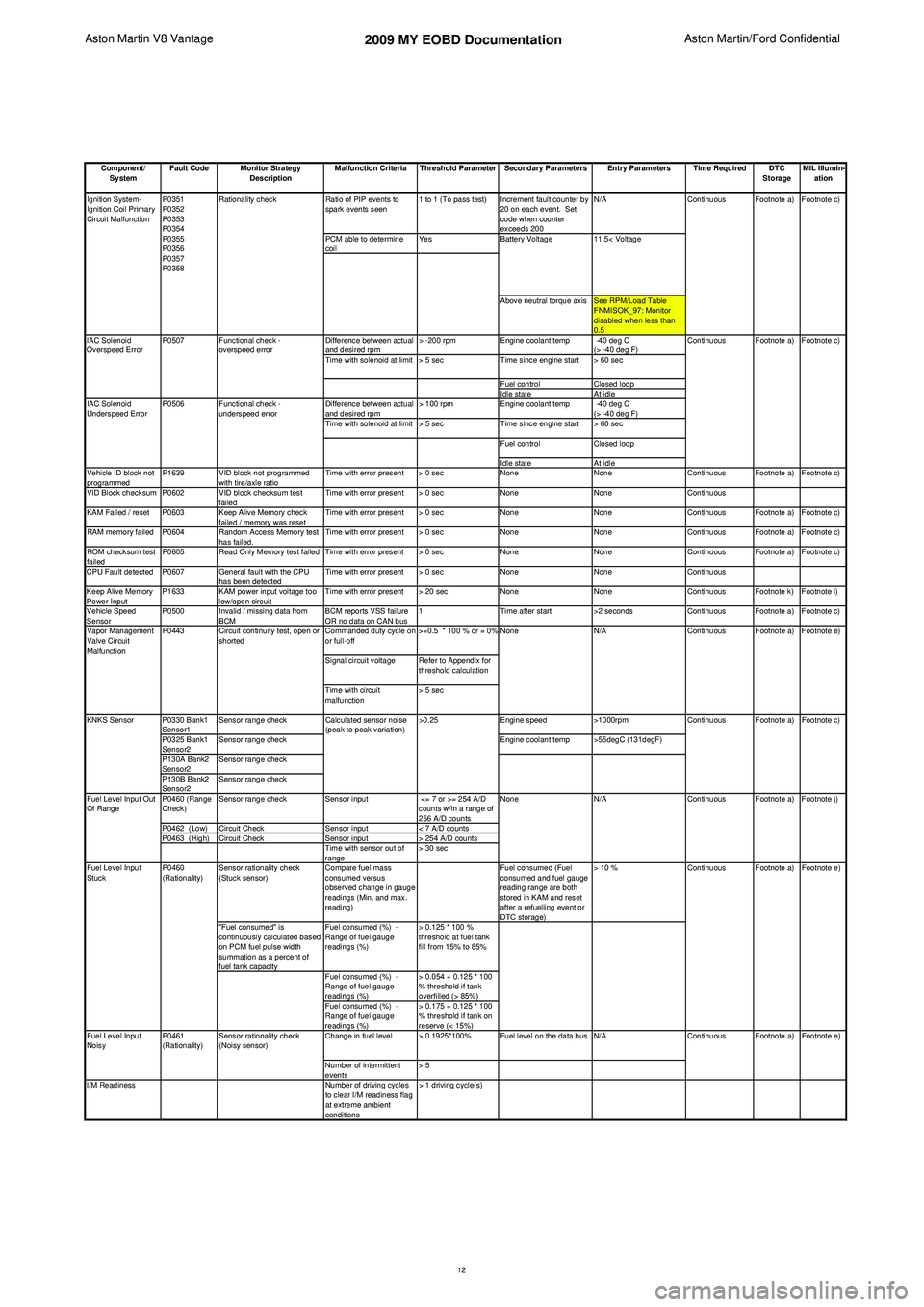
Aston Martin V8 Vantage 2009 MY EOBD DocumentationAston Martin/Ford Confidential
Component/ System Fault Code Monitor Strategy
Description Malfunction Criteria Threshold Parameter Secondary Parameters Entry Parameters Time Required DTC
StorageMIL Illumin-
ation
Ratio of PIP events to
spark events seen 1 to 1 (To pass test) Increment fault counter by
20 on each event. Set
code when counter
exceeds 200 N/A
PCM able to determine
coil Yes
Above neutral torque axis See RPM/Load Table FNMISOK_97: Monitor
disabled when less than
0.5
Difference between actual
and desired rpm > -200 rpm
Engine coolant temp -40 deg C
(> -40 deg F)
Time with solenoid at limit > 5 sec Time since engine start > 60 sec
Fuel control Closed loop
Idle state At idle
Difference between actual
and desired rpm > 100 rpm
Engine coolant temp -40 deg C
(> -40 deg F)
Time with solenoid at limit > 5 sec Time since engine start > 60 sec
Fuel control Closed loop
Idle state At idle
Vehicle ID block not
programmed P1639 VID block not programmed
with tire/axle ratio Time with error present > 0 sec
NoneNoneContinuous Footnote a) Footnote c)
VID Block checksum P0602 VID block checksum test failedTime with error present > 0 sec
NoneNoneContinuous
KAM Failed / reset P0603 Keep Alive Memory check failed / memory was resetTime with error present > 0 sec
NoneNoneContinuous Footnote a) Footnote c)
RAM memory failed P0604 Random Access Memory test has failed.Time with error present > 0 sec
NoneNoneContinuous Footnote a) Footnote c)
ROM checksum test
failed P0605 Read Only Memory test failed Time with error present > 0 sec
NoneNoneContinuous Footnote a) Footnote c)
CPU Fault detected P0607 General fault with the CPU has been detectedTime with error present > 0 sec
NoneNoneContinuous
Keep Alive Memory
Power Input P1633 KAM power input voltage too
low/open circuit Time with error present > 20 sec
NoneNoneContinuous Footnote k) Footnote i)
Vehicle Speed
Sensor P0500 Invalid / missing data from
BCM BCM reports VSS failure
OR no data on CAN bus1
Time after start >2 secondsContinuous Footnote a) Footnote c)
Commanded duty cycle on
or full-off >=0.5 * 100 % or = 0%
Signal circuit voltage Refer to Appendix for threshold calculation
Time with circuit
malfunction > 5 sec
P0330 Bank1
Sensor1 Sensor range check
Engine speed>1000rpm
P0325 Bank1
Sensor2 Sensor range check
Engine coolant temp >55degC (131degF)
P130A Bank2
Sensor2 Sensor range check
P130B Bank2
Sensor2 Sensor range check
P0460 (Range
Check) Sensor range check
Sensor input <= 7 or >= 254 A/D
counts w/in a range of
256 A/D counts
P0462 (Low) Circuit Check Sensor input< 7 A/D counts
P0463 (High) Circuit Check Sensor input> 254 A/D counts
Time with sensor out of
range > 30 sec
Sensor rationality check
(Stuck sensor) Compare fuel mass
consumed versus
observed change in gauge
readings (Min. and max.
reading) Fuel consumed (Fuel
consumed and fuel gauge
reading range are both
stored in KAM and reset
after a refuelling event or
DTC storage)> 10 %
"Fuel consumed" is
continuously calculated based
on PCM fuel pulse width
summation as a percent of
fuel tank capacity Fuel consumed (%) -
Range of fuel gauge
readings (%)
> 0.125 * 100 %
threshold at fuel tank
fill from 15% to 85%
Fuel consumed (%) -
Range of fuel gauge
readings (%) > 0.054 + 0.125 * 100
% threshold if tank
overfilled (> 85%)
Fuel consumed (%) -
Range of fuel gauge
readings (%) > 0.175 + 0.125 * 100
% threshold if tank on
reserve (< 15%)
Change in fuel level > 0.1925*100% Fuel level on the data bus N/A
Number of intermittent
events > 5
I/M Readiness Number of driving cycles
to clear I/M readiness flag
at extreme ambient
conditions > 1 driving cycle(s) Footnote e)
Footnote a)
Footnote c)
Footnote a) Footnote j) Footnote e)
Fuel Level Input
Noisy Continuous Footnote a)
Continuous Footnote a)
P0461
(Rationality) Sensor rationality check
(Noisy sensor)
Fuel Level Input
Stuck
P0460
(Rationality) Continuous
N/A Continuous
Calculated sensor noise
(peak to peak variation)
>0.25
KNKS Sensor
Fuel Level Input Out
Of Range NoneFootnote a) Footnote e)
Vapor Management
Valve Circuit
Malfunction P0443 Circuit continuity test, open or
shorted None
N/A Continuous
11.5< Voltage
Ignition System-
Ignition Coil Primary
Circuit Malfunction
IAC Solenoid
Underspeed Error P0507
P0506
Functional check -
overspeed error
Functional check -
underspeed error
IAC Solenoid
Overspeed Error
Footnote a) Footnote c)
Continuous
P0351
P0352
P0353
P0354
P0355
P0356
P0357
P0358
Rationality check
Continuous Footnote a) Footnote c)
Battery Voltage
12
Page 913 of 947

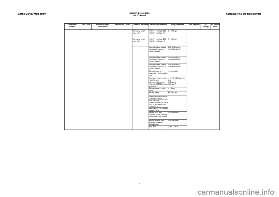
Aston Martin V12 Family
2009 MY V12 Family EOBDincl. V12 Vantage
Aston Martin/Ford Confidential
Component/ System Fault Code Monitor Strategy
Description Malfunction Criteria Threshold Parameter Secondary Parameters Entry Parameters Time Required DTC
StorageMIL Illumin-
ation
Rpm range for air
mass cell 2 HO2S11 switches : 200
HO2S21 switches: 200 0 - 4000 rpm
Rpm range for air
mass cell 3 HO2S11 switches : 200
HO2S21 switches: 200 0 - 4000 rpm
Inferred midbed catalyst
temp for air mass cell 1
(Bank1/Bank2) 371 - 871 deg C
(700-1600 deg F)
Inferred midbed catalyst
temp for air mass cell 2
(Bank1/Bank2) 371 - 871 deg C
(700-1600 deg F)
Inferred midbed catalyst
temp for air mass cell 3
(Bank1/Bank2) 371 - 871 deg C
(700-1600 deg F)
Time constant to
determine throttle position
rate 1.0 (Unitless)
Maximum throttle position
rate of change < 50 * 5/ 1024 volts per
sec
Minimum inferred rear
HO2S12/HO2S22 temp to
enter test 349 deg C
(660 deg F)
Time since part-throttle
decel > 1.0 sec
Vehicle speed 20 - 80 mph
Crankshaft position circuit
(PIP) OK (P0320)
HO2S Monitor
COMPLETE with no DTC
s
prior to final switch ratio
computation
Evap system OK, no Evap
System DTCs
EWMA "fast" filter
constant for first 2 driving
cycles after KAM cleared 0.99 (Unitless)
EWMA "normal" filter
constant after first 2
driving cycles 0.99 (Unitless)
Fuel level > .15 * 100 %
2
Page 914 of 947

Aston Martin V12 Family
2009 MY V12 Family EOBDincl. V12 Vantage
Aston Martin/Ford Confidential
Component/ System Fault Code Monitor Strategy
Description Malfunction Criteria Threshold Parameter Secondary Parameters Entry Parameters Time Required DTC
StorageMIL Illumin-
ation
P0300
to
P0312 Deviations in crankshaft
acceleration processed by
Neural Network Misfire
Monitor software and Catalyst
Temperature model Percentage misfire
required to exceed
Catalyst Damage
Temperature 900 deg c
(1650 deg F) catalyst
damage threshold, per
engine bank Type A: See RPM/Load
Table FNMISPCT_97 %
Type A:
200 revs
(Continuous)Type A:
Footnote b)
Type A:
Footnote d)
Full-range misfire capability Percentage misfire required to exceed
emission thresholdsType B: > 0.01 * 100
%
Type B:
1000 revs
(Continuous)Type B/C:
Footnote a)
Type B:
Footnote c)
Percentage misfire
required to clear emission
pending code < 0.001 * 100 % Time since engine start,
value based on time and
IAT 0 + FNMISACT sec
(See Transfer Functions)
Full-range misfire redline:
6900 rpm Time since PCM power up 0 sec
Time for NNMM
computation queue to fill4 revs from initial crank
(Meets 2 rev start delay
requirement)
Engine coolant temp -7 - 121 deg C ( 20 - 250 deg )
Engine rpm 500 - 4000rpm
Engine rpm in neutral
(Auto trans. only) < 3100 rpm
Net engine torque > -68 Nm ( -50 ft lbs)
Engine torque rate of
change > -34 Nm/s or < 41 Nm/s
(> -25 ft lbs/sec or
< 30 ft lbs/sec)
Throttle position rate of
change > -20 volts/background
loop or
< 30 * 5/1024
volts/background loop
Closed throttle
deceleration
(Dashpot mode) Closed throttle,
vehicle speed < 4 mph,
dashpot airflow adder
present
Engine rpm/load range See RPM/Load Table FNMISOK_97: Monitor
disabled when less than
0.5
Crankshaft position circuit
(PIP) OK (P0320)
Fuel shutoff for rpm or
vehicle speed limiting No fuel cutoff occurring
Fuel level > 0.15 * 100 %
Cylinder Misfire
Detected
Misfire Monitor
3
Page 917 of 947

Aston Martin V12 Family
2009 MY V12 Family EOBDincl. V12 Vantage
Aston Martin/Ford Confidential
Component/ System Fault Code Monitor Strategy
Description Malfunction Criteria Threshold Parameter Secondary Parameters Entry Parameters Time Required DTC
StorageMIL Illumin-
ationStream 1 (Front)
HO2S Circuit Slow
Response P0133
(Bank 1)
Monitor HO2S switching
frequency and amplitude
(Forced at 1.5 Hz fixed rate) Switching frequency
(Indicates gross failure)
< 0.0 Hz Time since entering close
d
loop fuel control> 10 sec < 4 sec once per
driving cycleFootnote a) Footnote c)
P0153
(Bank 2) Switching frequency
difference from desired
(Test run at correct
frequency)< 0.19 Hz
Short term fuel trim 0.9 - 1.1 * 100 %
Signal voltage amplitude < 0.55 volts Engine coolant temp and
ECT sensor OK
(P0117/0118) 55 - 116 deg C
(130 - 240 deg F)
Fuel level above minimum
level > 0.15 * 100 %
Intake air temp and IAT
sensor OK (P0112/0113) < 71 deg C
(< 160 deg F)
Engine load and MAF
sensor OK (P0102/0103) 0.15 - 0.4 * 100 %
Vehicle speed and
VSS (P0500) or
OSS (P0720) sensor OK 30 - 60 mph
Engine rpm and
crankshaft position circuit
(PIP) OK (P0230) 1000 - 2200 rpm
Throttle position sensor
OK (P0122/0123)
Camshaft ID circuit (CMP)
OK (P0340)
No Misfire Monitor DTCs
Fuel rail pressure sensor
OK (P0190/0192/0193)
Flex fuel composition not
changing
Not transitioning into/out o
f
Characteristic Shift Down
Not in Phase 0 of Evap
Monitor
No Purge System reset
Maximum change in
engine rpm while running
monitor < 160 rpm
Maximum change in
engine load while running
monitor < 0.13 * 100%
Maximum change in
vehicle speed while
running monitor < 2.0 mph
Maximum change in short
term fuel trim while
running monitor (PTEC
only) < 0.1
6
Page 925 of 947

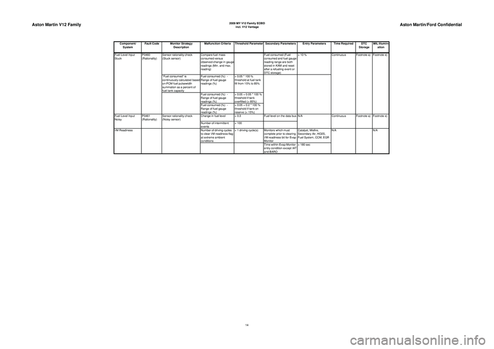
Aston Martin V12 Family
2009 MY V12 Family EOBDincl. V12 Vantage
Aston Martin/Ford Confidential
Component/ System Fault Code Monitor Strategy
Description Malfunction Criteria Threshold Parameter Secondary Parameters Entry Parameters Time Required DTC
StorageMIL Illumin-
ation
Sensor rationality check
(Stuck sensor) Compare fuel mass
consumed versus
observed change in gaug
e
readings (Min. and max.
reading) Fuel consumed (Fuel
consumed and fuel gauge
reading range are both
stored in KAM and reset
after a refueling event or
DTC storage)> 10 %
"Fuel consumed" is
continuously calculated based
on PCM fuel pulsewidth
summation as a percent of
fuel tank capacity Fuel consumed (%) -
Range of fuel gauge
readings (%)
> 0.05 * 100 %
threshold at fuel tank
fill from 15% to 85%
Fuel consumed (%) -
Range of fuel gauge
readings (%) > 0.05 + 0.05 * 100 %
threshold if tank
overfilled (> 85%)
Fuel consumed (%) -
Range of fuel gauge
readings (%) > 0.05 + 0.2 * 100 %
threshold if tank on
reserve (< 15%)
Change in fuel level > 0.3 Fuel level on the data bus
Number of intermittent
events > 100
Number of driving cycles
to clear I/M readiness flag
at extreme ambient
conditions > 1 driving cycle(s) Monitors which must
complete prior to clearing
I/M readiness bit for Evap
Monitor Catalyst, Misfire,
Secondary Air, HO2S,
Fuel System, CCM, EGR
Time within Evap Monitor
entry condition except IAT
and BARO > 180 sec N/A
I/M Readiness N/AFootnote e)
Fuel Level Input
Noisy P0461
(Rationality)Sensor rationality check
(Noisy sensor) N/A
Continuous Footnote a) Footnote e)
Continuous Footnote a)
Fuel Level Input
Stuck P0460
(Rationality)
14