USB ASTON MARTIN V8 VANTAGE 2010 Workshop Manual
[x] Cancel search | Manufacturer: ASTON MARTIN, Model Year: 2010, Model line: V8 VANTAGE, Model: ASTON MARTIN V8 VANTAGE 2010Pages: 947, PDF Size: 43.21 MB
Page 658 of 947

Battery System (14.01)
Power Supply (14.00)
May 2007 Workshop Manual 14-1-3
Charging Circuit
Electrical power generated at the alternator flows via two ‘T Pi ece’ connectors to the engine bay ‘Dirty Feed’ stud. It then
flows via the Battery Disconnect Switch (BDS) to the battery positive terminal. Both the alternator and the battery are
earthed via the vehicle body to complete the charging circuit.
The starter motor and the ‘jump start terminal’ ar e also fed directly from the charging circuit.
Go to page 18-X-XX for complete power dist ribution circuit diagram (Circuit Sheet 25).
+12 Volt Distribution
The +12 volt supply comes from the battery to the battery disc onnect switch (BDS). Assuming that this switch is not
activated, 12 volt power is then available from C0046-8 on the BDS to all of the clean feed battery studs.
The following clean feeds are then live:
• Boot fuse box clean feed
• Under bonnet fuse box clean feed
• CEM busbars 1, 2, 3 and 4 clean feeds
12V power to all systems and components is then controlled by the CEM and the under bonnet / boot fuse boxes.
Page 690 of 947

May 2007 Workshop Manual 18-1-1
Electric Distribution/Electronic Control (18.00)
Contents
Wiring and Circuit Protection (18.01) ................. 18-1-2Fuse Boxes .............................................................. 1-2 Engine Bay Fuse/Relay Box..................................... 1-2
Central Electronics Module Fusebox....................... 1-3
How to Read the Circuits........................................ 1-4 Wires ..................................................................... 1-4
Controller Area Network (CAN).............................. 1-5
Media Oriented System Transport (MOST) ............. 1-6
Connectors ............................................................. 1-6 Splices ................................................................... 1-7
Relays .................................................................... 1-8
Busbars .................................................................. 1-8
Fuses ..................................................................... 1-8
Resistors................................................................. 1-9
Lamps .................................................................... 1-9
Switches ................................................................ 1-9
Motors and Pumps ................................................. 1-9
Diodes ................................................................. 1-10
Transistor ............................................................. 1-10
Earth / Ground ..................................................... 1-10
Maintenance ......................................................... 1-11 Forward Harness-Renew ...................................... 1-11
Header Latch Harness-Renew
(Roadster Only) .................................................... 1-12
Roof Cylinder Wiring Harness-Renew
(Roadster Only) .................................................... 1-14
Transaxle Harness-Renew .................................... 1-21
Engine Wiring Harness-Renew ............................. 1-22
Facia Harness-Renew ........................................... 1-25
Cabin Harness Assembly-Renew .......................... 1-26
Passenger Door Harness-Renew ........................... 1-36
Driver’s Door Harness-Renew .............................. 1-36
Rear Bumper Harness-Renew .............................. 1-37
Transaxle Harness-Renew .................................... 1-37
Axle Transmission Harness-Renew
-Sportshift Only.................................................... 1-38
Tailgate Harness-Renew ....................................... 1-38
Vehicle Control System (18.08) ........................... 18-2-1 Module Configuration ............................................ 2-1 Principles of Operation .......................................... 2-1
Market Configuration ............................................. 2-1
Customer Configuration ......................................... 2-1
Data Buses .............................................................. 2-1
Network Bus ........................................................... 2-1 MOST.................................................................... 2-1
Module Locations ................................................... 2-2
Page 697 of 947

Wiring and Circuit Protection (18.01)
Electric Distribution/E lectronic Control (18.00)
18-1-8 Workshop Manual May 2007
Relays
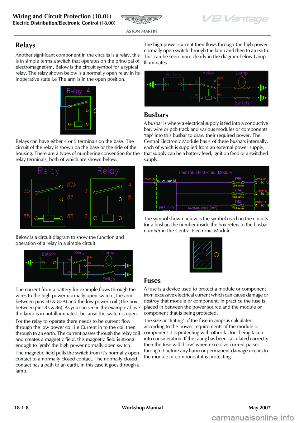
Another significant component in the circuits is a relay, this
is in simple terms a switch that operates on the principal of
electromagnetism. Below is the circuit symbol for a typical
relay. The relay shown below is a normally open relay in its
inoperative state i.e The arm is in the open position.
Relays can have either 4 or 5 terminals on the base. The
circuit of the relay is shown on the base or the side of the
housing. There are 2 types of numbering convention for the
relay terminals, both of which are shown below.
Below is a circuit diagram to show the function and
operation of a relay in a simple circuit.
The current from a battery for example flows through the
wires to the high power normally open switch (The arm
between pins 30 & 87A) and the low power coil (The box
between pins 85 & 86). As you can see in the example above
the lamp is in not illuminated, because the switch is open.
For the relay to operate there needs to be current flow
through the low power coil i.e Current in to the coil then
through to an earth. The current passes through the relay coil
and creates a magnetic field, this magnetic field is strong
enough to ‘grab’ the high power normally open switch.
The magnetic field pulls the switch from it’s normally open
contact to a normally closed contact. The normally closed
contact has a path to an earth, in this case it goes through a
lamp. The high power current then flows through the high power
normally open switch through the lamp and then to an earth.
This can be seen more clearly in the diagram below.Lamp
Illuminates
Busbars
A busbar is where a electrical
supply is fed into a conductive
bar, wire or pcb track and various modules or components
‘tap’ into this busbar to draw their required power. The
Central Electronic Module has 4 of these busbars internally,
each of which is supplied from an external power supply,
that supply can be a battery feed, ignition feed or a switched
supply.
The symbol shown below is the symbol used on the circuits
for a busbar, the number inside the box refers to the busbar
number in the Central Electronic Module.
Fuses
A fuse is a device used to protect a module or component
from excessive electrical current which can cause damage or
destroy that module or component. In practice the fuse is
placed in between the power source and the module or
component that is being protected.
The size or ‘Rating’ of the fuse in amps is calculated
according to the power requirements of the module or
component it is protecting with other factors being taken
into consideration. If the rating has been calculated correctly
then the fuse will ‘blow’ when excessive current passes
through it before any harm or permanent damage occurs to
the module or component it is protecting.