clock ASTON MARTIN V8 VANTAGE 2010 User Guide
[x] Cancel search | Manufacturer: ASTON MARTIN, Model Year: 2010, Model line: V8 VANTAGE, Model: ASTON MARTIN V8 VANTAGE 2010Pages: 947, PDF Size: 43.21 MB
Page 266 of 947

Engine Structure (03.01)
3-1-18Workshop ManualIssue 4, November 2008
3. Using valve spring compressor, compress valve spring,
install collets.
4. Release/remove spring compressor.
5. Install selective tappet buckets in their original fitted positions.
6. Lubricate intake and exhaust camshaft bearings and journals with clean engine oil.
7. Install intake and exhaust camshafts, install bearing caps (x20), install bolts (x40).
8. Torque tighten bearing cap bolts in the correct sequence.
9. Install camshaft sprocket Torx bolts in intake and exhaust camshafts.
10. Rotate intake camshaft clockwise, check and log each valve clearance using feeler gauges.
11. Calculate the correct tappet bucket grade.
12. Remove bearing cap bolts (x40), remove bearing caps (x20), remove intake and exhaust camshafts.
13. Remove tappet buckets, install selected tappet buckets.
14. Install intake and exhaust camshafts, install bearing caps (x20), install bolts (x40).
15. Torque tighten bearing cap bolts in the correct sequence.
16. Rotate intake and exhaust camshafts clockwise, re- check each valve clearance using feeler gauges.
17. Remove camshaft sprocket Torx bolts (x4).
18. Remove bearing cap bolts (x40), remove bearing caps (x20), remove intake and exhaust camshafts.
19. Install spark plugs.
20. Install cylinder head gaskets - engine set (see Workshop Manual procedure 03.10.AL Gasket - Cylinder Head -
Engine Set - Renew).
Spring (Inlet Valve Set) - Renew
Removal
1. Remove cylinder head gaskets - engine set (see Workshop Manual procedure 03.10.AL Gasket -
Cylinder Head - Engine Set - Renew).
2. Remove spark plugs from cylinder heads (x8).
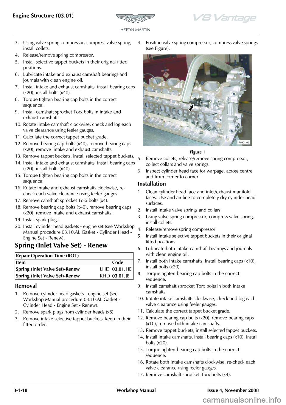
3. Remove intake selective tappet buckets, keep in their fitted order. 4. Position valve spring compressor, compress valve springs
(see Figure).
Figure 1
5. Remove collets, release/remove spring compressor, collect collars and valve springs.
6. Inspect cylinder head face for warpage, across centre and from corner to corner.
Installation
1. Clean cylinder head face and inlet/exhaust manifold faces. Use and air line to completely dry cylinder head
surfaces.
2. Install intake valve springs and collars.
3. Using valve spring compressor, compress valve spring, install collets.
4. Release/remove spring compressor.
5. Install intake selective tappet buckets in their original fitted positions.
6. Lubricate both intake camsh aft bearings and journals
with clean engine oil.
7. Install both intake camshafts, install bearing caps (x10), install bolts (x20).
8. Torque tighten bearing cap bolts in the correct sequence.
9. Install camshaft sprocket Torx bolts in both intake camshafts.
10. Rotate intake camshafts clockwise, check and log each valve clearance using feeler gauges.
11. Calculate the correct tappet bucket grade.
12. Remove bearing cap bolts (x20), remove bearing caps (x10), remove both intake camshafts.
13. Remove tappet buckets, install selected tappet buckets.
14. Install intake camshafts, inst all bearing caps (x10), install
bolts (x20).
15. Torque tighten bearing cap bolts in the correct sequence.
16. Rotate both intake camshafts clockwise, re-check each valve clearance using feeler gauges.
17. Remove camshaft sprocket Torx bolts (x4).
Repair Operation Time (ROT)
A0301310
Page 267 of 947

Engine Structure (03.01)
Issue 4, November 2008Workshop Manual 3-1-19
18. Remove bearing cap bolts (x20), remove bearing caps
(x10), remove both intake camshafts.
19. Install spark plugs.
20. Install cylinder head gaskets - engine set (see Workshop Manual procedure 03.10.AL Gasket - Cylinder Head -
Engine Set - Renew).
Inlet and Exhaust Valve Seal (Engine Set)
- Renew
Removal
1. Remove cylinder head gaskets - engine set (see Workshop Manual procedure 03.10.AL Gasket -
Cylinder Head - Engine Set - Renew).
2. Remove spark plugs (x8).
3. Remove selective tappet buckets, keep in their fitted order.
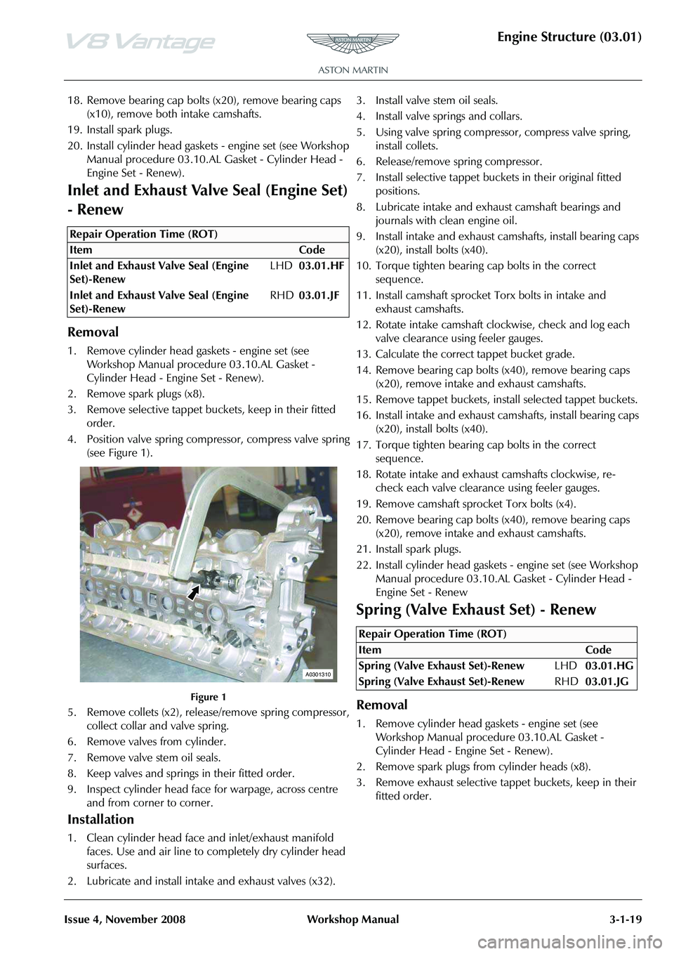
4. Position valve spring compressor, compress valve spring (see Figure 1).
Figure 1
5. Remove collets (x2), release/remove spring compressor, collect collar and valve spring.
6. Remove valves from cylinder.
7. Remove valve stem oil seals.
8. Keep valves and springs in their fitted order.
9. Inspect cylinder head face for warpage, across centre and from corner to corner.
Installation
1. Clean cylinder head face and inlet/exhaust manifold faces. Use and air line to completely dry cylinder head
surfaces.
2. Lubricate and install intake and exhaust valves (x32). 3. Install valve stem oil seals.
4. Install valve springs and collars.
5. Using valve spring compressor, compress valve spring,
install collets.
6. Release/remove spring compressor.
7. Install selective tappet buckets in their original fitted positions.
8. Lubricate intake and exhaust camshaft bearings and journals with clean engine oil.
9. Install intake and exhaust camshafts, install bearing caps (x20), install bolts (x40).
10. Torque tighten bearing cap bolts in the correct sequence.
11. Install camshaft sprocket Torx bolts in intake and exhaust camshafts.
12. Rotate intake camshaft clockwise, check and log each valve clearance using feeler gauges.
13. Calculate the correct tappet bucket grade.
14. Remove bearing cap bolts (x40), remove bearing caps (x20), remove intake and exhaust camshafts.
15. Remove tappet buckets, install selected tappet buckets.
16. Install intake and exhaust camshafts, install bearing caps (x20), install bolts (x40).
17. Torque tighten bearing cap bolts in the correct sequence.
18. Rotate intake and exhaust camshafts clockwise, re- check each valve clearance using feeler gauges.
19. Remove camshaft sprock et Torx bolts (x4).
20. Remove bearing cap bolts (x40), remove bearing caps (x20), remove intake and exhaust camshafts.
21. Install spark plugs.
22. Install cylinder head gaskets - engine set (see Workshop Manual procedure 03.10.AL Gasket - Cylinder Head -
Engine Set - Renew
Spring (Valve Exhaust Set) - Renew
Removal
1. Remove cylinder head gaskets - engine set (see Workshop Manual procedure 03.10.AL Gasket -
Cylinder Head - Engine Set - Renew).
2. Remove spark plugs from cylinder heads (x8).
3. Remove exhaust selective tappet buckets, keep in their fitted order.
Repair Operation Time (ROT)
A0301310
Repair Operation Time (ROT)
Page 268 of 947

Engine Structure (03.01)
3-1-20Workshop ManualIssue 4, November 2008
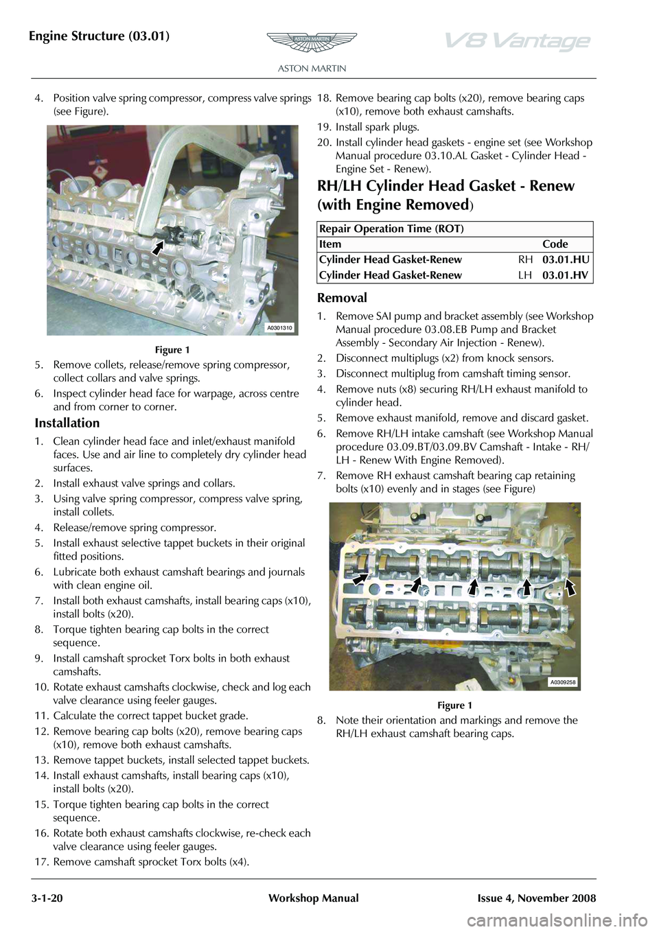
4. Position valve spring compressor, compress valve springs
(see Figure).
Figure 1
5. Remove collets, release/re move spring compressor,
collect collars and valve springs.
6. Inspect cylinder head face for warpage, across centre and from corner to corner.
Installation
1. Clean cylinder head face and inlet/exhaust manifold faces. Use and air line to completely dry cylinder head
surfaces.
2. Install exhaust valve springs and collars.
3. Using valve spring compressor, compress valve spring, install collets.
4. Release/remove spring compressor.
5. Install exhaust selective tappet buckets in their original fitted positions.
6. Lubricate both exhaust camshaft bearings and journals with clean engine oil.
7. Install both exhaust camshafts , install bearing caps (x10),
install bolts (x20).
8. Torque tighten bearing cap bolts in the correct sequence.
9. Install camshaft sprocket Torx bolts in both exhaust camshafts.
10. Rotate exhaust camshafts clockwise, check and log each valve clearance using feeler gauges.
11. Calculate the correct tappet bucket grade.
12. Remove bearing cap bolts (x20), remove bearing caps (x10), remove both exhaust camshafts.
13. Remove tappet buckets, install selected tappet buckets.
14. Install exhaust camshafts, install bearing caps (x10), install bolts (x20).
15. Torque tighten bearing cap bolts in the correct sequence.
16. Rotate both exhaust camshafts clockwise, re-check each valve clearance using feeler gauges.
17. Remove camshaft sprocket Torx bolts (x4). 18. Remove bearing cap bolts (x20), remove bearing caps
(x10), remove both exhaust camshafts.
19. Install spark plugs.
20. Install cylinder head gaskets - engine set (see Workshop Manual procedure 03.10.AL Gasket - Cylinder Head -
Engine Set - Renew).
RH/LH Cylinder Head Gasket - Renew
(with Engine Removed
)
Removal
1. Remove SAI pump and bracket assembly (see Workshop Manual procedure 03.08. EB Pump and Bracket
Assembly - Secondary Ai r Injection - Renew).
2. Disconnect multiplugs (x2) from knock sensors.
3. Disconnect multiplug from camshaft timing sensor.
4. Remove nuts (x8) securing RH/LH exhaust manifold to
cylinder head.
5. Remove exhaust manifold, remove and discard gasket.
6. Remove RH/LH intake camshaft (see Workshop Manual procedure 03.09.BT/03.09.BV Camshaft - Intake - RH/
LH - Renew With Engine Removed).
7. Remove RH exhaust camshaft bearing cap retaining bolts (x10) evenly and in stages (see Figure)
Figure 1
8. Note their orientation and markings and remove the RH/LH exhaust camshaft bearing caps.
A0301310
Repair Operation Time (ROT)
ItemCode
Cylinder Head Gasket-Renew RH03.01.HU
Cylinder Head Gasket-Renew LH03.01.HV
A0309258
Page 269 of 947

Engine Structure (03.01)
Issue 4, November 2008Workshop Manual 3-1-21
9. Remove RH/LH exhaust camshaft (see Figure 2).
Figure 2
10. Remove bolts (x2) securing front end of RH/LH cylinder
head to cylinder block.
11. Remove bolts (x10), evenly and in stages securing RH/ LH cylinder head to cylinder block (see Figure 3).
Figure 3
12. With assistance, remove RH /LH cylinder head assembly.
13. Remove and discard cylinder head gasket.
Installation
1. Thoroughly clean RH/LH cylinder head face and retaining bolt pockets.
2. Thoroughly clean RH/LH cylinder block face.
3. Thoroughly clean and dry RH cylinder head retaining
bolts.
4. Install new RH/LH cylinder gasket, locate on dowels.
5. With assistance, install RH/LH cylinder head, locate on dowels.
6. Install and torque tighten cylinder head bolts (x12) in the correct sequence.
7. Lubricate RH exhaust camsha ft journals, camshaft lobes,
bearing surfaces on cylinder head and bearing caps with
clean engine oil.
8. Install RH exhaust camshaft, install bearing caps (x5) in their original positions.
9. Install bolts (x10) and torque tighten in the sequence specified.
10. Install sprocket retaining Torx bolt in camshaft. 11. Rotate camshaft accordingly and check each valve
clearance using feeler gauges.
12. Remove sprocket retaining Torx bolt.
13. Install RH intake camsha ft (see Workshop Manual
procedure (03.09.BT/03.09.BV) Camshaft - Intake - RH/
LH - Renew With Engine Removed).
14. Install timing chain tensioni ng tool (303-532) into RH/
LH exhaust camshaft sprocket.
15. Apply a force to the tool (3 03-532) in an anti-clockwise
direction and torque tighten RH/LH sprocket Torx bolts.
Remove special tool.
16. Connect multiplug to camshaft timing sensor.
17. Connect multiplugs (x2) to knock sensors.
18. Clean RH/LH exhaust manifold.
19. Install new RH/LH exhaust manifold gasket, install exhaust manifold.
20. Install and torque tighten RH/LH exhaust manifold nuts (x8).
21. Install SAI pump and bracket assembly (see Workshop Manual procedure 03.08. EB Pump and Bracket
Assembly - Secondary Air Injection - Renew).
Cylinder Head Gasket (Engine Set) -
Renew (with Engine Removed)
Removal
1. Remove SAI pump and bracke t assembly (see Workshop
Manual procedure 03.08.EB Pump and Bracket
Assembly - Secondary Air Injection - Renew).
2. Disconnect multiplugs (x4) from LH and RH knock sensors.
3. Disconnect multiplugs (x2) from LH and RH camshaft
timing sensors.
4. Remove nuts (x8) securing LH exhaust manifold to cylinder head.
5. Remove LH exhaust manifold, remove and discard gasket.
6. Remove LH intake camshaft (see Workshop Manual procedure 03.09.BV Camshaft - Intake - LH - Renew
With Engine Removed).
A0309260
A0310319
Repair Operation Time (ROT)
Page 272 of 947

Engine Structure (03.01)
3-1-24Workshop ManualIssue 4, November 2008
23. Remove RH exhaust camshaft bearing cap retaining
bolts (x10) evenly and in stages (see Figure 10).
Figure 10
24. Note their orientation and markings and remove the RH exhaust camshaft bearing caps.
25. Remove RH exhaust camshaft (see Figure 11).
Figure 11
26. Remove bolts (x2) securing front end of RH cylinder head to cylinder block.
27. Remove bolts (x10), evenly and in stages securing RH cylinder head to cylinder block (see Figure 12).
Figure 12
28. With assistance, remove RH cylinder head assembly.
29. Remove and discard cylinder head gasket.
Installation
1. Thoroughly clean LH and RH cylinder head faces and retaining bolt pockets.
2. Thoroughly clean LH and RH cylinder block faces.
3. Thoroughly clean and dry LH and RH cylinder head retaining bolts.
4. Install new RH cylinder gasket, locate on dowels.
5. With assistance, install RH cylinder head, locate on dowels.
6. Install and torque tighten cylinder head bolts (x12) in the correct sequence.
7. Lubricate camshaft journals , camshaft lobes, bearing
surfaces on cylinder head and bearing caps with clean
engine oil.
8. Install RH exhaust camshaft, install bearing caps (x5) in their original positions.
9. Install bolts (x10) and torque tighten in the sequence specified.
10. Install sprocket retaining Torx bolt in camshaft.
11. Rotate camshaft accordingly and check each valve clearance using feeler gauges.
12. Repeat procedure and install RH intake camshaft.
13. Remove sprocket retaining Torx bolt.
14. Rotate RH intake and exhaust camshafts until timing flats on each camshaft face uppermost.
15. Install tool (303-530) to RH cylinder head to secure camshafts, install and tighten bolts (x3).
16. Install new LH cylinder gasket, locate on dowels.
17. With assistance, install LH cylinder head, locate on dowels.
18. Install and torque tighten cylinder head bolts (x12) in the correct sequence.
19. Lubricate LH exhaust camshaf t journals, camshaft lobes,
bearing surfaces on cylinder head and bearing caps with
clean engine oil.
20. Install LH exhaust camshaft, install bearing caps (x5) in their original positions.
21. Install bolts (x10) and torque tighten in the sequence specified.
22. Install sprocket retaining Torx bolt in LH exhaust camshaft.
23. Rotate LH exhaust camshaft accordingly and check each valve clearance using feeler gauges.
24. Remove sprocket retaining Torx bolt.
25. Install LH intake camshaft (see Workshop Manual procedure 03.09.BV Camshaft - Intake - LH - Renew
With Engine Removed).
26. Install timing chain tensio ning tool (303-532) into RH
exhaust camshaft sprocket.
27. Apply a force to the tool (303-532) in an anti-clockwise direction and torque tighten RH sprocket Torx bolts.
Remove special tool.
28. Connect multiplugs to LH and RH camshaft timing sensors.
A0309258
A0309260
A0310319
Page 327 of 947

Valve Train (03.09)
Engine (03.00)
Issue 5, January 2010 Workshop Manual 3-9-1
Engine (03.00)
Valve Train (03.09)
Specifications
Maintenance
Left Side Timing Chain Arm Assembly -
Remove and Install
Remove
1. Remove the engine timing cover. (03.10.AF - Engine Timing Cover). 2. Remove the two screws that attach the special tool to
the engine.
Figure 1
3. Remove the special tool from the flywheel.
Figure 2
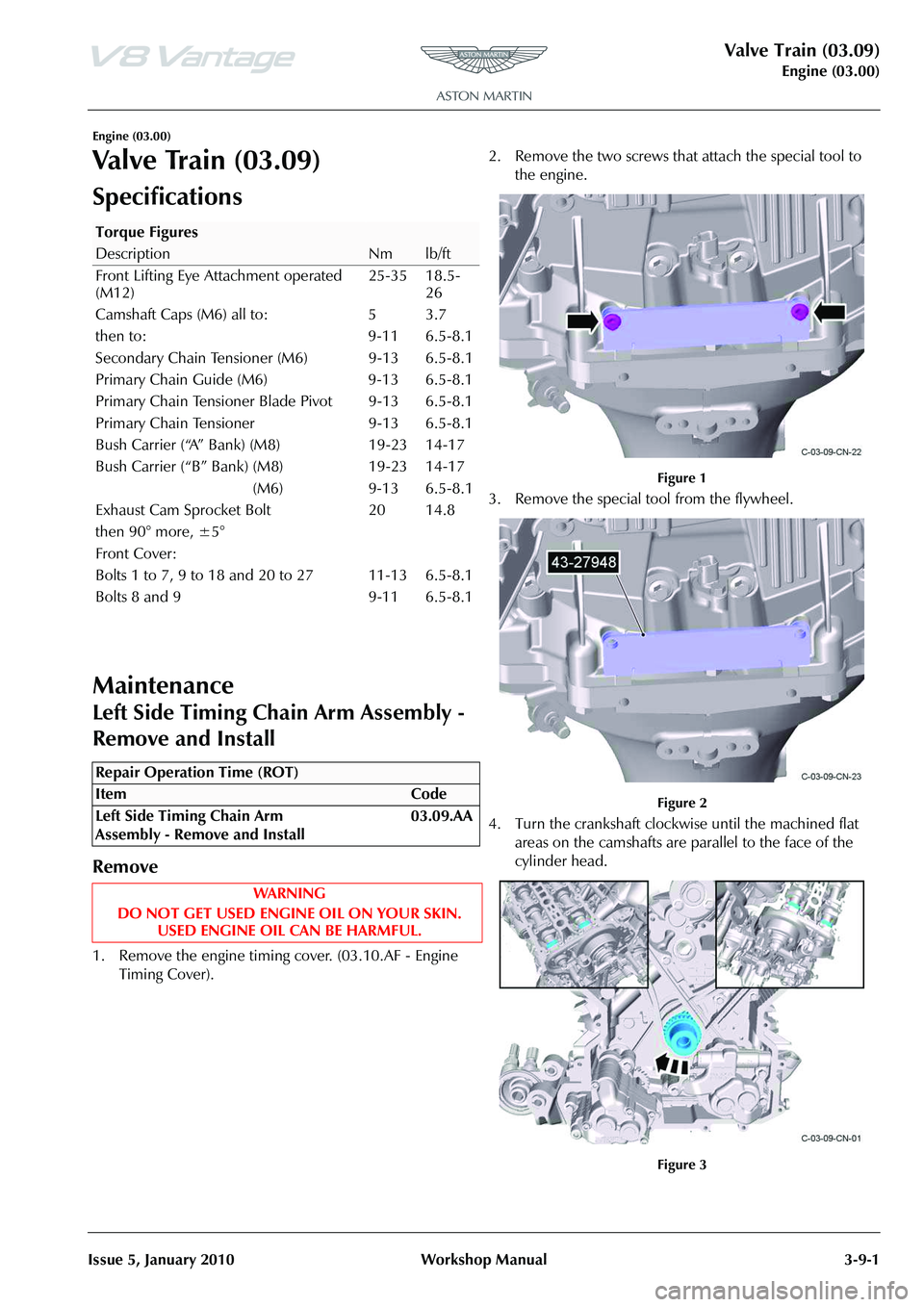
4. Turn the crankshaft clockwise until the machined flat areas on the camshafts are parallel to the face of the
cylinder head.
Figure 3
Torque Figures
DescriptionNmlb/ft
Front Lifting Eye Attachment operated
(M12) 25-35 18.5-
26
Camshaft Caps (M6) all to: 5 3.7
then to: 9-11 6.5-8.1
Secondary Chain Tensioner (M6) 9-13 6.5-8.1
Primary Chain Guide (M6) 9-13 6.5-8.1
Primary Chain Tensioner Blade Pivot 9-13 6.5-8.1
Primary Chain Tensioner 9-13 6.5-8.1
Bush Carrier (“A” Bank) (M8) 19-23 14-17
Bush Carrier (“B” Bank) (M8) 19-23 14-17
(M6) 9-13 6.5-8.1
Exhaust Cam Sprocket Bolt
then 90° more, ±5° 20 14.8
Front Cover:
Bolts 1 to 7, 9 to 18 and 20 to 27
Bolts 8 and 9 11-13
9-116.5-8.1
6.5-8.1
Repair Operation Time (ROT)
Page 331 of 947

Valve Train (03.09)
Engine (03.00)
Issue 5, January 2010 Workshop Manual 3-9-5
25. Loosen the two Torx bolts that attach the camshaft sprockets to the camshafts.
Figure 22
Install
1. Install the tensioner arm (refer to Figure 21).
2. Install the special bolt that attaches the tensioner arm to the engine and torque the bolt to 11 Nm (refer to
Figure 20).
3. Install the timing chain tens ioner (refer to Figure 19).
4. Install the two bolts that attach the timing chain tensioner to the engine and torque the bolts to 11 Nm
(refer to Figure 18).
5. Install the special tool on the exhaust camshaft sprocket.
Figure 23
6. Use the special tool to turn the exhaust sprocket counterclockwise until there is tension in the chain.
Figure 24
7. Release the pin from the ti ming chain tensioner and let
the tension piston gradually apply tension to the timing
chain.
Figure 25
Note: You must use the special tool to hold the timing chain
in the correct position during the subsequent two steps of
the procedure.
Note: Make sure that the tensio ner is fully operated but do
not use too much force.
Page 333 of 947

Valve Train (03.09)
Engine (03.00)
Issue 5, January 2010 Workshop Manual 3-9-7
16. Remove the special tool from the flywheel.
Figure 31
17. Lower the vehicle.
18. Remove the three screws that attach the special tool to the cylinder head.
Figure 32
19. Remove the special tool from the left side camshaft.
Figure 33
20. Remove the three screws that attach the special tool to the cylinder head.
Figure 34
21. Remove the special tool from the right side camshaft.
Figure 35
22. Turn the crankshaft two full revolutions clockwise.
23. Use the applicable equipment to lift the vehicle and make it safe.
Caution:
During the step that follows, if you feel any increase in
resistance, do not force the crankshaft. If you do you
can damage the engine. If you cannot turn the
crankshaft, you must do the engine timing procedure again.
Page 334 of 947

Valve Train (03.09)
Engine (03.00)3-9-8 Workshop Manual Issue 5, January 2010
24. Install the special tool onto the flywheel.
Figure 36
25. Install and tighten the two screws that attach the special tool to the engine.
Figure 37
26. Install the engine timing cover (refer to procedure 03.10.AF - Engine Timing Cover).
Right Side Timing Chain Arm Assembly -
Remove and Install
Remove
1. Remove the engine timing cover. (03.10.AF - Engine Timing Cover). 2. Remove the two screws that attach the special tool to
the engine.
Figure 1
3. Remove the special tool from the flywheel.
Figure 2
4. Turn the crankshaft clockwise until the machined flat
areas on the camshafts are parallel to the face of the
cylinder head.
Figure 3
5. Install the special tool on the right side camshaft.
Repair Operation Time (ROT)
Note: If necessary, use special tool 303-530-04 with this
step.
Page 338 of 947

Valve Train (03.09)
Engine (03.00)3-9-12 Workshop Manual Issue 5, January 2010
2. Install and torque the special bolt that attaches the tensioner arm to the engine to 11 Nm (refer to
Figure 19).
3. Install the timing chain tens ioner (refer to Figure 18).
4. Install and torque the two bolts that attach the timing chain tensioner to the engine to 11 Nm (refer to
Figure 17).
5. Install the special tool on the exhaust camshaft sprocket.
Figure 22
6. Use the special tool to turn the exhaust sprocket counterclockwise until the chain is tight.
Figure 23
7. Release the pin from the ti ming chain tensioner and let
the tension piston gradually tension the timing chain.
Figure 24
8. Torque the two Torx bolts that attach the camshaft
sprockets to the camshafts to 20 Nm.
Figure 25
9. Torque the two Torx bolts that attach the camshaft sprockets to the camshafts 90 degrees more (refer to
Figure 25).
Note: You must use the special
tool to hold the timing chain
in the correct position during the subsequent two steps of
the procedure.
Note: Make sure that the tensio ner is fully operated but do
not use too much force.
Note: Make sure that you torque the bolt that attaches the
sprocket to the exhaust camsha ft first in the step that
follows.
Note: Make sure that you torque the bolt that attaches the
sprocket to the exhaust camsha ft first in the step that
follows.