infotainment ASTON MARTIN V8 VANTAGE 2010 Workshop Manual
[x] Cancel search | Manufacturer: ASTON MARTIN, Model Year: 2010, Model line: V8 VANTAGE, Model: ASTON MARTIN V8 VANTAGE 2010Pages: 947, PDF Size: 43.21 MB
Page 692 of 947

Wiring and Circuit Protection (18.01)
Electric Distribution/Electronic Control (18.00)
May 2007 Workshop Manual 18-1-3
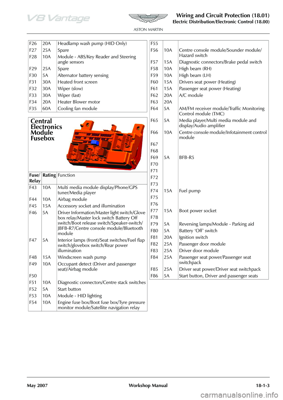
F26 20A Headlamp wash pump (HID Only)
F27 25A Spare
F28 10A Module - ABS/Key Reader and Steering angle sensors
F29 25A Spare
F30 5A Alternator battery sensing
F31 30A Heated front screen
F32 30A Wiper (slow)
F33 30A Wiper (fast)
F34 20A Heater Blower motor
F35 60A Cooling fan module
Central
Electronics
Module
Fusebox
Fuse/
RelayRatingFunction
F43 10A Multi media module display/Phone/GPS tuner/Media player
F44 10A Airbag module
F45 15A Accessory socket and illumination
F46 5A Driver Information/Master light switch/Glove box relay/Master lock switch Battery Off
switch/Boot release switch/Speaker-switch/
JBFB-R7/Centre console module/Bluetooth
module
F47 5A Interior lamps (front)/Seat switches/Fuel flap switch/glovebox switch/Rear power
illumination
F48 15A Windscreen wash pump
F49 10A Occupant detect (Driver and passenger seat)/Airbag module
F50
F51 10A Diagnostic connectors/Centre stack switches
F52 5A Start button
F53 10A Module - HID lighting
F54 10A Engine fuse box/Boot fuse box/Tyre pressure monitor module/Satellite navigation relay
F55
F56 10A Centre console module/Sounder module/
Hazard switch
F57 15A Diagnostic connectors/Brake pedal switch
F58 10A High beam (RH)
F59 10A High beam (LH)
F60 15A Drivers seat power (Heating)
F61 15A Passenger seat power (Heating)
F62 20A A/C module
F63 20A
F64 5A AM/FM receiver module/Traffic Monitoring Control module (TMC)
F65 5A Media player/Multi media module and display/Audio amplifier
F66 10A Centre console module/Infotainment control module
F67
F68
F69 5A BFB-R5
F70
F71
F72
F73
F74 15A Fuel pump
F75
F76
F77 15A Boot power socket
F78
F79 5A Reversing lamps/Module - Parking aid
F80 5A Battery ‘Off’ switch
F81 20A Ignition switch
F82 25A Passenger door module
F83 25A Driver door module
F84 25A Passenger seat power/Passenger seat switchpack
F85 25A Driver seat power/Driver seat switchpack
F86 5A Start button, Driver and passenger seats
Page 730 of 947

Vehicle Control System (18.08)
Electric Distribution/Electronic Control (18.00)
May 2007 Workshop Manual 18-2-1
Electric Distribution/Electronic Control (18.00)
Vehicle Control System (18.08)
Module Configuration
Principles of Operation
All configurable modules ar e packaged in a kit which
contains a warning label and a multi-language sheet re-
emphasizing the requirements to configure replacement
modules.
Replacement configurable modules must be configured
using WDS.
Market Configuration
This data is required so that modules can interact with the
vehicle correctly. By using WDS this data will be retrieved in
the following ways:
• Indirectly from a mirrored image of the old modules data stored in an ‘As is’ database on DCS
• Indirectly from information stored in WDS
Configuration
The complexity of the electronics involved with module
configuration and the multiplex communication network
which they are connected to preclude the use of general
workshop electrical test equipment.
WDS contains detailed instructions on module
configuration.
Install the new module(s) and download the ‘As is’ data
using the vehicle configuration software on WDS.
Customer Configuration
There are certain modules / functions that the customer may
or may not want reconfigured or enabled. Some of these
preferences are accessed through the ‘in-car’ menus,
available on the infotainment centre. Others are set in the
vehicle configuration or specific software files, these items
can be toggled or configured by WDS.
The ‘As is’ database (AML) holds customer original
preferences. When a new module is installed to a previously
upgraded or reconfigured vehicle these preferences can
retrieved and re-applied as required through WDS
Data Buses
The primary data required for control and operation is
carried on CAN data buses.
Two Can buses are used:
• High Speed CAN bus operates at 500 k bits / sec and is primarily used to transmit powertrain data
• The Powertrain (high speed) CAN bus operates at 500 k bits / sec and is only used to link the two PCMs
• Low Speed CAN bus operates at 125 k bits / sec and is used to transmit data relevant to the body system.
Network Bus
MOST
The MOST network bus is a fibr e optical network used only
for the Infotainment System
WDS will permanently retain th e configuration information
Page 731 of 947

Vehicle Control System (18.08)
Electric Distribution/Electronic Control (18.00)
18-2-2 Workshop Manual May 2007
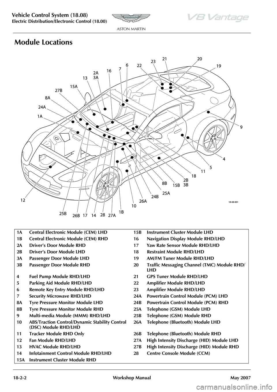
Module Locations
1A Central Electronic Module (CEM) LH D15BInstrument Cluster Module LHD
1B Central Electronic Module (CEM) RH D 16 Navigation Display Module RHD/LHD
2A Driver’s Door Module RHD 17 Yaw Rate Sensor Module RHD/LHD
2B Driver’s Door Module LHD 1 8Restraint Module RHD/LHD
3A Passenger Door Module LHD 19 AM/FM Tuner Module RHD/LHD
3B Passenger Door Module RHD 20 Traffic Messaging Channel (TMC) Module RHD/
LHD
4 Fuel Pump Module RHD/LHD 21 GPS Tuner Module RHD/LHD
5 Parking Aid Module RHD/LHD 22 Amplifier Module RHD/LHD
6 Remote Key Entry Module RHD/LH D23Amplifier Module RHD/LHD
7 Security Microwave RHD/LHD 24A Powe rtrain Control Module (PCM) LHD
8A Tyre Pressure Monitor Module LHD 24B Powertrain Control Module (PCM) RHD
8B Tyre Pressure Monitor Module RHD 25A Telephone (GSM) Module LHD
9Multi-media Module (MMM) RHD/LHD 25B Teleph one (GSM) Module RHD
10 ABS/Traction Control/Dy namic Stability Control
(DSC) Module RHD/LHD 26A Telephone (Bluetooth) Module LHD
11 Tracker Module RHD Only 26B Tel ephone (Bluetooth) Module RHD
12 Fan Module RHD/LHD 27A High Intensity Discharge (HID) Module LHD
13 HVAC Module RHD/LHD 27B High Intensity Discharge (HID) Module RHD
14 Infotainment Control Module RHD/ LHD 28 Centre Console Module (CCM)
15A Instrument Cluster Module RHD