differential ASTON MARTIN V8 VANTAGE 2010 User Guide
[x] Cancel search | Manufacturer: ASTON MARTIN, Model Year: 2010, Model line: V8 VANTAGE, Model: ASTON MARTIN V8 VANTAGE 2010Pages: 947, PDF Size: 43.21 MB
Page 837 of 947
Electronics Training Programme
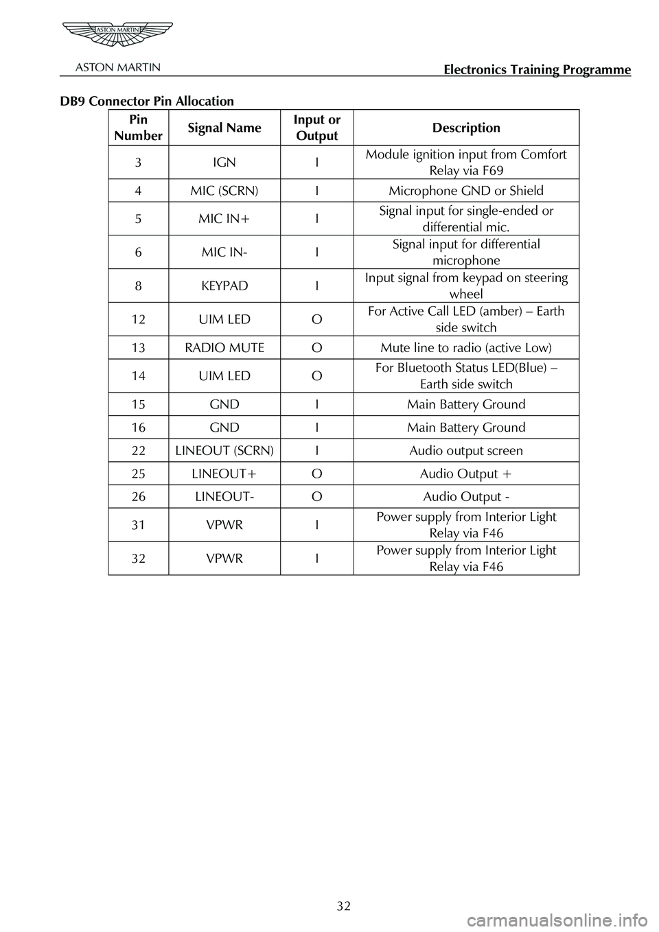
DB9 Connector Pin Allocation
Pin
Number Signal Name Input or
Output Description
3 IGN I Module ignition input from Comfort
Relay via F69
4 MIC (SCRN) I Microphone GND or Shield
5 MIC IN+ I Signal input for single-ended or
differential mic.
6 MIC IN- I Signal input for differential microphone
8 KEYPAD I Input signal from keypad on steering
wheel
12 UIM LED O For Active Call LED (amber) – Earth side switch
13 RADIO MUTE O Mute line to radio (active Low)
14 UIM LED O For Bluetooth Status LED(Blue) – Earth side switch
15 GND I Main Battery Ground
16 GND I Main Battery Ground
22 LINEOUT (SCRN) I Audio output screen
25 LINEOUT+ O Audio Output +
26 LINEOUT- O Audio Output -
31 VPWR I Power supply from Interior Light Relay via F46
32 VPWR I Power supply from Interior Light Relay via F46
32
Page 848 of 947

AML EOBD System Operation Summary
Rory O’Curry Aston Martin Lagonda CONFIDENTIAL 1 May 2009
[email protected] AML EOBD Monitors 07 ROC.doc Page 2 of 43
AML EOBD System Operation
Summary for Gasoline Engines.
Contents
Introduction ........................................................................................................................................................................................3
Catalyst Efficiency Monitor ...............................................................................................................................................................4
Misfire Monitor..................................................................................................................................................................................6
Fuel System Monitor ..........................................................................................................................................................................9
HO2S Monitor............................................................................................................................... ...................................................10
Differential Pressure Feedback EGR System Monitor.....................................................................................................................13
Electronic Throttle Monitor............................................................................................................................... ...............................16
Dual MAF Diagnostic............................................................................................................................... .......................................18
SAIR Monitor............................................................................................................................... ....................................................22
VCT Monitor............................................................................................................................... .....................................................25
Comprehensive Component Monitor - Engine............................................................................................................................... ..27
Comprehensive Component Monitor - Manual Transmission..........................................................................................................30
Comprehensive Component Monitor - Automatic Transmission .....................................................................................................31
6HP26 Automatic Transmission............................................................................................................................... ........................34
Auto Shift Manual (ASM) Transmission............................................................................................................................... ...........34
Inspection Maintenance Readiness Code............................................................................................................................... ..........35
Tamper Protection............................................................................................................................... .............................................35
Serial Data Link Connector............................................................................................................................... ...............................35
Serial Data Link Communication Protocol............................................................................................................................... ........35
Serial Data Link MIL Illumination............................................................................................................................... ....................36
Glossary of Terms............................................................................................................................... .............................................37
MIL Code List............................................................................................................................... ...................................................39
MIL Symbol............................................................................................................................... ......................................................43
Page 859 of 947
AML EOBD System Operation Summary
Rory O’Curry Aston Martin Lagonda CONFIDENTIAL 1 May 2009
[email protected] AML EOBD Monitors 07 ROC.doc Page 13 of 43
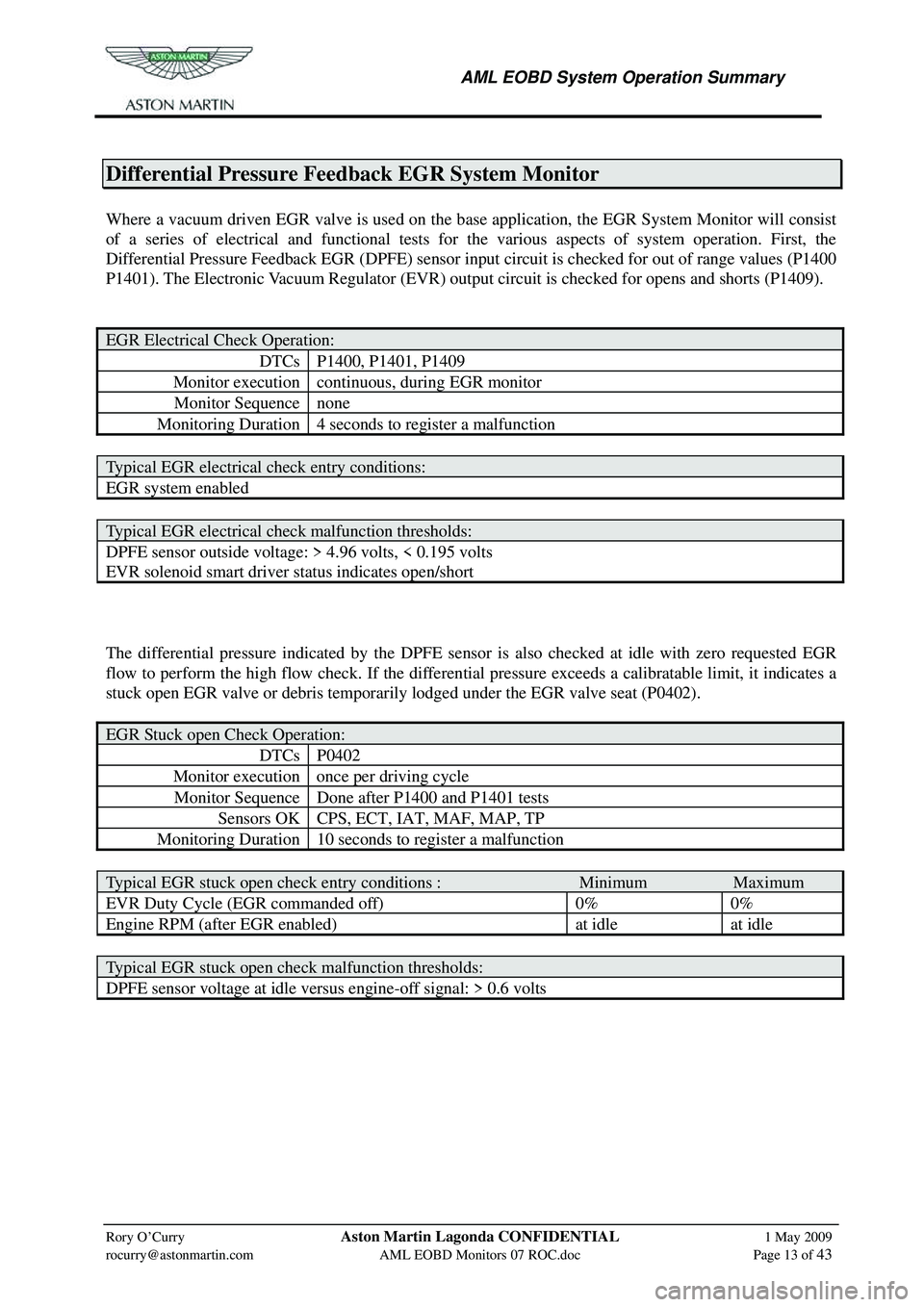
Differential Pressure Feedback EGR System Monitor
Where a vacuum driven EGR valve is used on the base application, the EGR System Monitor will consist
of a series of electrical and functional tests for the various aspects of system operation. First, the
Differential Pressure Feedback EGR (DPFE) sensor input circuit is checked for out of range values (P1400
P1401). The Electronic Vacuum Regulator (EVR) output circuit is checked for opens and shorts (P1409).
EGR Electrical Check Operation:
DTCs P1400, P1401, P1409
Monitor execution continuous, during EGR monitor
Monitor Sequence none
Monitoring Duration 4 seconds to register a malfunction
Typical EGR electrical check entry conditions:
EGR system enabled
Typical EGR electrical check malfunction thresholds:
DPFE sensor outside voltage: > 4.96 volts, < 0.195 volts
EVR solenoid smart driver status indicates open/short
The differential pressure indicated by the DPFE sensor is also checked at idle with zero requested EGR
flow to perform the high flow check. If the differen tial pressure exceeds a calibratable limit, it indicates a
stuck open EGR valve or debris temporar ily lodged under the EGR valve seat (P0402).
EGR Stuck open Check Operation:
DTCs P0402
Monitor execution once per driving cycle
Monitor Sequence Done after P1400 and P1401 tests
Sensors OK CPS, ECT, IAT, MAF, MAP, TP
Monitoring Duration 10 seconds to register a malfunction
Typical EGR stuck open check entry conditions : Minimum Maximum
EVR Duty Cycle (EGR commanded off) 0% 0%
Engine RPM (after EGR enabled) at idle at idle
Typical EGR stuck open check malfunction thresholds:
DPFE sensor voltage at idle versus engine-off signal: > 0.6 volts
Page 860 of 947
AML EOBD System Operation Summary
Rory O’Curry Aston Martin Lagonda CONFIDENTIAL 1 May 2009
[email protected] AML EOBD Monitors 07 ROC.doc Page 14 of 43
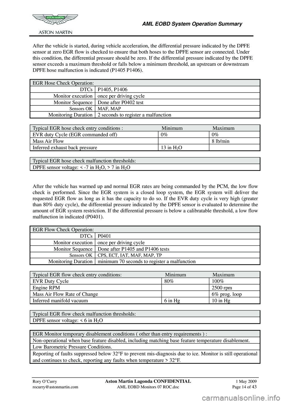
After the vehicle is started, during vehicle acceleration, the differential pressure indicated by the DPFE
sensor at zero EGR flow is checked to ensure that both hoses to the DPFE sensor are connected. Under
this condition, the differential pressure should be zer o. If the differential pressure indicated by the DPFE
sensor exceeds a maximum threshold or falls below a minimum threshold, an upstream or downstream
DPFE hose malfunction is indicated (P1405 P1406).
EGR Hose Check Operation:
DTCs P1405, P1406
Monitor execution once per driving cycle
Monitor Sequence Done after P0402 test
Sensors OK MAF, MAP
Monitoring Duration 2 seconds to register a malfunction
Typical EGR hose check entry conditions : Minimum Maximum
EVR duty Cycle (EGR commanded off) 0% 0%
Mass Air Flow 8 lb/min
Inferred exhaust back pressure 13 in H2O
Typical EGR hose check malfunction thresholds:
DPFE sensor voltage: < -7 in H2O, > 7 in H2O
After the vehicle has warmed up and normal EGR rates are being commanded by the PCM, the low flow
check is performed. Since the EGR system is a closed loop system, the EGR system will deliver the
requested EGR flow as long as it has the capacity to do so. If the EVR duty cycle is very high (greater
than 80% duty cycle), the differential pressure indicated by the DPFE sensor is evaluated to determine the
amount of EGR system restriction. If the differential pr essure is below a calibratable threshold, a low flow
malfunction in indicated (P0401).
EGR Flow Check Operation:
DTCs P0401
Monitor execution once per driving cycle
Monitor Sequence Done after P1405 and P1406 tests
Sensors OK CPS, ECT, IAT, MAF, MAP, TP
Monitoring Duration minimum 70 seconds to register a malfunction
Typical EGR flow check entry conditions: Minimum Maximum
EVR Duty Cycle 80% 100%
Engine RPM 2500 rpm
Mass Air Flow Rate of Change 6% prog. loop
Inferred manifold vacuum 6 in Hg 10 in Hg
Typical EGR flow check malfunction thresholds:
DPFE sensor voltage: < 6 in H2O
EGR Monitor temporary disablement conditions ( other than entry requirements ) :
Non-operational when base feature disabled, including matching base feature temperature disablement.
Low Barometric Pressure Conditions.
Reporting of faults suppressed below 32° F to prevent mis-diagnosis due to ice. Monitor is still operational
and continues to check, reporting any faults when temperature > 32 °F.
Page 893 of 947
Aston Martin V8 Vantage 2009 MY EOBD DocumentationAston Martin/Ford Confidential
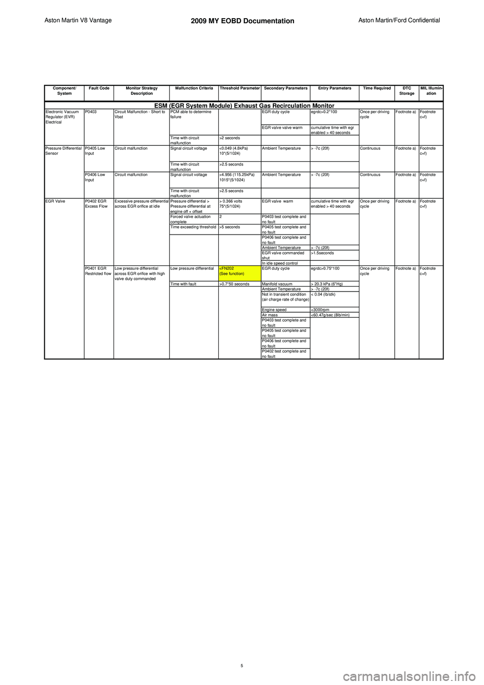
Component/ System Fault Code Monitor Strategy
Description Malfunction Criteria Threshold Parameter Secondary Parameters Entry Parameters Time Required DTC
StorageMIL Illumin-
ation
EGR duty cycle egrdc>0.2*100
EGR valve valve warm cumulative time with egr enabled > 40 seconds
Time with circuit
malfunction >2 seconds
Signal circuit voltage <0.049 (4.8kPa) 10*(5/1024)Ambient Temperature > -7c (20f)
Time with circuit
malfunction >2.5 seconds
Signal circuit voltage >4.956 (115.25kPa) 1015*(5/1024)Ambient Temperature > -7c (20f)
Time with circuit
malfunction >2.5 seconds
Pressure differential >
Pressure differential at
engine off + offset > 0.366 volts
75*(5/1024)
EGR valve warm cumulative time with egr
enabled > 40 seconds
Forced valve actuation
complete 2
P0403 test complete and
no fault
Time exceeding threshold >5 seconds P0405 test complete and
no fault
P0406 test complete and
no fault
Ambient Temperature > -7c (20f)
EGR valve commanded
shut >1.5seconds
In idle speed control
Low pressure differential
Time with fault >0.7*50 seconds Manifold vacuum > 20.3 kPa (6"Hg)
Ambient Temperature > -7c (20f)
Not in transient condition
(air charge rate of change) < 0.04 (lb/stk)
Engine speed <3000rpm
Air mass <60.47g/sec (8lb/min)
P0403 test complete and
no fault
P0405 test complete and
no fault
P0406 test complete and
no fault
P0402 test complete and
no fault
P0402 EGR
Excess Flow
Excessive pressure differential
across EGR orifice at idle
Electronic Vacuum
Regulator (EVR)
Electrical
P0403 Circuit Malfunction - Short to
Vbat PCM able to determine
failure
Footnote
c+f)
Footnote
c+f)
Footnote a) Footnote
c+f)
Continuous
Continuous Footnote a) Footnote
c+f)
Once per driving
cycle
Footnote a)ESM (EGR System Module) Exhaust Gas Recirculation Monitor
P0401 EGR
Restricted flowLow pressure differential
across EGR orifice with high
valve duty commanded Footnote a)
Once per driving
cycle
Pressure Differential
Sensor
P0405 Low
Input
P0406 Low
InputCircuit malfunction
Circuit malfunction
EGR Valve
Footnote
c+f)
Once per driving
cycle Footnote a)
5
Page 903 of 947
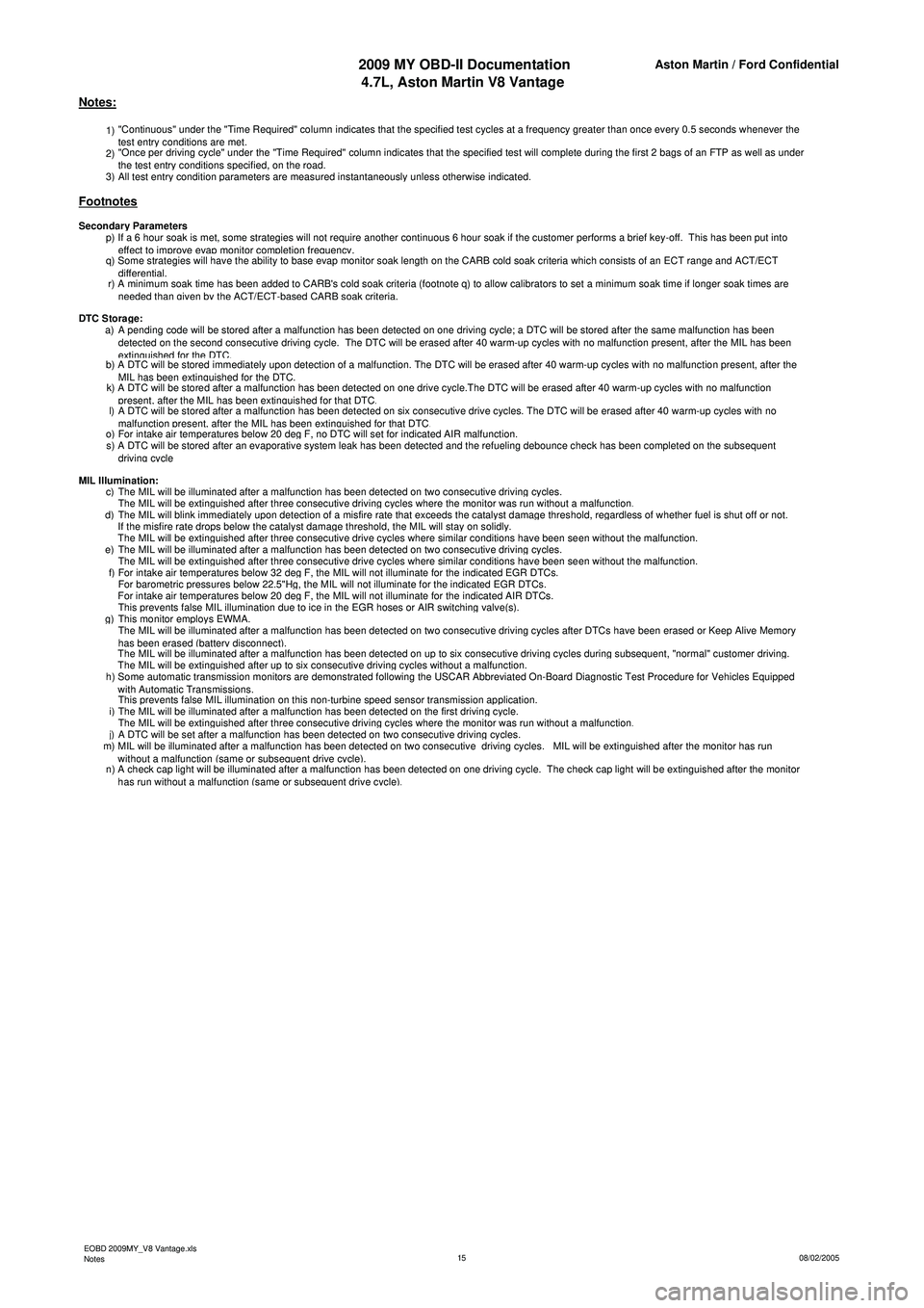
2009 MY OBD-II Documentation4.7L, Aston Martin V8 VantageAston Martin / Ford Confidential
1) "Continuous" under the "Time Required" column indicates that the specified test cycles at a frequency greater than once every 0.5 seconds whenever the
test entry conditions are met.
2) "Once per driving cycle" under the "Time Required" column indicates that the specified test will complete during the first 2 bags of an FTP as well as under
the test entr
y conditions specified, on the road.
3)All test entry condition parameters are measured instantaneously unless otherwise indicated.
p) If a 6 hour soak is met, some strategies will not require another continuous 6 hour soak if the customer performs a brief key-off. This has been put into
effect to improve evap monitor completion frequency.
q) Some strategies will have the ability to base evap monitor soak length on the CARB cold soak criteria which consists of an ECT range and ACT/ECT
differential.
r) A minimum soak time has been added to CARB's cold soak criteria (footnote q) to allow calibrators to set a minimum soak time if longer soak times are
n
eeded than given by the ACT/ECT-based CARB soak criteria.
a) A pending code will be stored after a malfunction has been detected on one driving cycle; a DTC will be stored after the same malfunction has been detected on the second consecutive driving cycle. The DTC will be erased after 40 warm-up cycles with no malfunction present, after the MIL has been
extinguished for the DTC.b) A DTC will be stored immediately upon detection of a malfunction. The DTC will be erased after 40 warm-up cycles with no malfunction present, after the MIL has been extinguished for the DTC.k) A DTC will be stored after a malfunction has been detected on one drive cycle.The DTC will be erased after 40 warm-up cycles with no malfunction present, after the MIL has been extinguished for that DTC.l) A DTC will be stored after a malfunction has been detected on six consecutive drive cycles. The DTC will be erased after 40 warm-up cycles with no malfunction present, after the MIL has been extinguished for that DTC.o)For intake air temperatures below 20 deg F, no DTC will set for indicated AIR malfunction.
s) A DTC will be stored after an evaporative system leak has been detected and the refueling debounce check has been completed on the subsequent
driving cycle
c)The MIL will be illuminated after a malfunction has been detected on two consecutive driving cycles.
The MIL will be extinguished after three consecutive driving cycles where the monitor was run without a malfunction.d)The MIL will blink immediately upon detection of a misfire rate that exceeds the catalyst damage threshold, regardless of whether fuel is shut off or not.
If the misfire rate drops below the catalyst damage threshold, the MIL will stay on solidly.
The MIL will be extinguished after three consecutive drive cycles where similar conditions have been seen without the malfunction.e)The MIL will be illuminated after a malfunction has been detected on two consecutive driving cycles.
The MIL will be extinguished after three consecutive drive cycles where similar conditions have been seen without the malfunction.f)For intake air temperatures below 32 deg F, the MIL will not illuminate for the indicated EGR DTCs.
For barometric pressures below 22.5"Hg, the MIL will not illuminate for the indicated EGR DTCs.
For intake air temperatures below 20 deg F, the MIL will not illuminate for the indicated AIR DTCs.
This prevents false MIL illumination due to ice in the EGR hoses or AIR switching valve(s).g)This monitor employs EWMA.
The MIL will be illuminated after a malfunction has been detected on two consecutive driving cycles after DTCs have been erased or Keep Alive Memory
h
as been erased (battery disconnect).
The MIL will be illuminated after a malfunction has been detected on up to six consecutive driving cycles during subsequent, "normal" customer driving.
The MIL will be extinguished after up to six consecutive driving cycles without a malfunction.
h) Some automatic transmission monitors are demonstrated following the USCAR Abbreviated On-Board Diagnostic Test Procedure for Vehicles Equipped
wi
th Automatic Transmissions.
This prevents false MIL illumination on this non-turbine speed sensor transmission application.
i)The MIL will be illuminated after a malfunction has been detected on the first driving cycle.
The MIL will be extinguished after three consecutive driving cycles where the monitor was run without a malfunction.j)A DTC will be set after a malfunction has been detected on two consecutive driving cycles.
m) MIL will be illuminated after a malfunction has been detected on two consecutive driving cycles. MIL will be extinguished after the monitor has run
wi
thout a malfunction (same or subsequent drive cycle).
n) A check cap light will be illuminated after a malfunction has been detected on one driving cycle. The check cap light will be extinguished after the monitor
h
as run without a malfunction (same or subsequent drive cycle).
MIL Illumination:
Notes:
Footnotes
Secondary Parameters
DTC Stora
ge:
EOBD 2009MY_V8 Vantage.xls
Notes 08/02/2005
15
Page 930 of 947

Aston Martin V12 Family
2009 MY V12 Family EOBDincl. V12 Vantage
Aston Martin/Ford Confidential
Notes:
1) "Continuous" under the "Time Required" column indicates that the specified test cycles at a frequency greater than once every 0.5
seconds whenever the test entr
y conditions are met.
2) "Once per driving cycle" under the "Time Required" column indicates that the specified test will complete during the first 2 bags of an
FTP as well as under the test entry conditions s
pecified
, on the road.
3
)All test entr
y condition
parameters are measured instantaneousl
y unless otherwise indicated.
Footnotes:Secondar
y Parameters:
p) If a 6 hour soak is met, some strategies will not require another continuous 6 hour soak if the customer performs a brief key-off. This
has been put into effect to im
prove eva
p monitor com
pletion fre
quenc
y.
q) Some strategies will have the ability to base evap monitor soak length on the CARB cold soak criteria which consists of an ECT range
and ACT/ECT differential.
r) A minimum soak time has been added to CARB's cold soak criteria (footnote q) to allow calibrators to set a minimum soak time if
lon
ger soak times are needed than
given b
y the ACT/ECT-based CARB soak criteria.
DTC Stora
ge:
a) A pending code will be stored after a malfunction has been detected on one driving cycle; a DTC will be stored after the same
malfunction has been detected on the second consecutive drivin
g cycle. The DTC will be erased after 40 warm-u
p cycles with no ma
b) A DTC will be stored immediately upon detection of a malfunction. The DTC will be erased after 40 warm-up cycles with no malfunction
present
, after the MIL has been extin
guished for the DTC.
k) A DTC will be stored after a malfunction has been detected on one drive cycle.The DTC will be erased after 40 warm-up cycles with no
malfunction
present
, after the MIL has been extin
guished for that DTC.
l) A DTC will be stored after a malfunction has been detected on six consecutive drive cycles. The DTC will be erased after 40 warm-up
c
ycles with no malfunction
present
, after the MIL has been extin
guished for that DTC.
o
)For intake air tem
peratures below 20 de
g F, no DTC will set for indicated AIR malfunction.
s) A pending code will be stored after a malfunction has been detected on upto the 6th trip depending on the size of the fault deviation; a
DTC will be stored after the same malfunction has been detected on a second driving cycle. The DTC will be erased after 40 warm-up
cycles with no malfunction. This monitor employs EVMA.
MIL Illumination:c)The MIL will be illuminated after a malfunction has been detected on two consecutive drivin
g cycles.
The MIL will be extin
guished after three consecutive drivin
g cycles where the monitor was run without a malfunction.
d) The MIL will blink immediately upon detection of a misfire rate that exceeds the catalyst damage threshold, regardless of whether fuel
is shut off or not.
If the misfire rate dro
ps below the catal
yst dama
ge threshold
, the MIL will sta
y on solidl
y.
The MIL will be extin
guished after three consecutive drive c
ycles where similar conditions have been seen without the malfunction.
e
)The MIL will be illuminated after a malfunction has been detected on two consecutive drivin
g cycles.
19