headlamp ASTON MARTIN V8 VANTAGE 2010 User Guide
[x] Cancel search | Manufacturer: ASTON MARTIN, Model Year: 2010, Model line: V8 VANTAGE, Model: ASTON MARTIN V8 VANTAGE 2010Pages: 947, PDF Size: 43.21 MB
Page 688 of 947

Lighting Mechanisms (17.04)
Lighting (17.00)
May 2007 Workshop Manual 17-4-1
Lighting (17.00)
Lighting Mechanisms (17.04)
Headlamp Levelling (HID Only)
The ‘Automatic Dynamic He adlamp Levelling System’
consists of:
• An Automatic Dynamic Headla mp Levelling System ECU
• A level sensor for the front suspension
• A level sensor for the rear suspension
• A bi-polar stepper motor mounted in the housing of each headlamp
The Automatic Dynamic Headlamp Levelling System
prevents the dipped beam dazzling oncoming road traffic by
varying the angular position of the dipped (and main beam)
headlamp units relative to the position of the vehicles
suspension.
Static condition - Compensates for boot or occupant load
condition.
Dynamic condition - Compensates for suspension
movements due to acceleration and deceleration. The
sensitivity of the system is dependent on vehicle speed and
the rate of change of the vehicle speed.
High amplitude low frequency inputs such as those caused
by potholes are filtered out to desensitise the system in
constant speed situations.
17-04-001
Page 692 of 947
Wiring and Circuit Protection (18.01)
Electric Distribution/Electronic Control (18.00)
May 2007 Workshop Manual 18-1-3
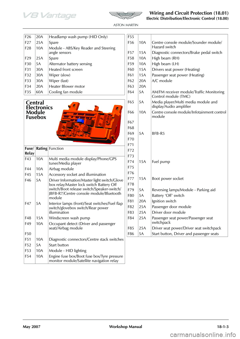
F26 20A Headlamp wash pump (HID Only)
F27 25A Spare
F28 10A Module - ABS/Key Reader and Steering angle sensors
F29 25A Spare
F30 5A Alternator battery sensing
F31 30A Heated front screen
F32 30A Wiper (slow)
F33 30A Wiper (fast)
F34 20A Heater Blower motor
F35 60A Cooling fan module
Central
Electronics
Module
Fusebox
Fuse/
RelayRatingFunction
F43 10A Multi media module display/Phone/GPS tuner/Media player
F44 10A Airbag module
F45 15A Accessory socket and illumination
F46 5A Driver Information/Master light switch/Glove box relay/Master lock switch Battery Off
switch/Boot release switch/Speaker-switch/
JBFB-R7/Centre console module/Bluetooth
module
F47 5A Interior lamps (front)/Seat switches/Fuel flap switch/glovebox switch/Rear power
illumination
F48 15A Windscreen wash pump
F49 10A Occupant detect (Driver and passenger seat)/Airbag module
F50
F51 10A Diagnostic connectors/Centre stack switches
F52 5A Start button
F53 10A Module - HID lighting
F54 10A Engine fuse box/Boot fuse box/Tyre pressure monitor module/Satellite navigation relay
F55
F56 10A Centre console module/Sounder module/
Hazard switch
F57 15A Diagnostic connectors/Brake pedal switch
F58 10A High beam (RH)
F59 10A High beam (LH)
F60 15A Drivers seat power (Heating)
F61 15A Passenger seat power (Heating)
F62 20A A/C module
F63 20A
F64 5A AM/FM receiver module/Traffic Monitoring Control module (TMC)
F65 5A Media player/Multi media module and display/Audio amplifier
F66 10A Centre console module/Infotainment control module
F67
F68
F69 5A BFB-R5
F70
F71
F72
F73
F74 15A Fuel pump
F75
F76
F77 15A Boot power socket
F78
F79 5A Reversing lamps/Module - Parking aid
F80 5A Battery ‘Off’ switch
F81 20A Ignition switch
F82 25A Passenger door module
F83 25A Driver door module
F84 25A Passenger seat power/Passenger seat switchpack
F85 25A Driver seat power/Driver seat switchpack
F86 5A Start button, Driver and passenger seats
Page 700 of 947

Wiring and Circuit Protection (18.01)
Electric Distribution/Electronic Control (18.00)
May 2007 Workshop Manual 18-1-11
Maintenance
Forward Harness-Renew
Removal
1. Disconnect vehicle battery.
2. Remove LH headlamp (see Workshop Manual procedure 17.01.AB Headlamp Assembly - LH -
Renew).
3. Remove RH headlamp (see Workshop Manual procedure 17.01.BB Headlamp Assembly - RH -
Renew).
4. Release grommet from body, feed harness from inside of vehicle.
5. Disconnect multiplugs (x2) LH and RH side repeaters.
6. Disconnect multiplugs (x2) LH and RH pad wear indicators.
7. Disconnect multiplug (x2) LH and RH wheel speed sensors.
8. Disconnect multiplugs (x2) LH and RH air flow meters.
9. Disconnect multiplugs (x2) LH and RH headlamp bulb
monitoring resistors.
10. Remove nuts (x6) securing LH and RH earth leads to body (x6).
11. Remove screws (x4) LH and RH harness plate to body and release harness from plate.
12. Remove screen washer reservoir (see Workshop Manual procedure 01.16.DA Reserv oir and Motor Assembly -
Windshield Wash - Renew).
13. Remove fusebox (see Workshop Manual procedure 18.01.KD Fuse Box - Engine Bay - Renew).
14. Disconnect multiplug (x1) purge valve.
15. Disconnect multiplug (x1) ABS modulator.
16. Disconnect multiplug (x1) load level sensor.
17. Disconnect multiplugs (x4) forward harness to cabin harness.
18. Remove wiper motor and linkage (see Workshop Manual procedure 01.16.BA Linkage Assembly - Wiper
- Renew).
19. Remove cross member fr ont latch mounting (see
Workshop Manual procedure 01.14.BD Latch Assembly
- Hood - Renew).
20. Remove nuts (x2) securing earth leads to body (x2).
21. Disconnect multiplug (x1) heated front windshield.
22. Disconnect multiplug PAS sensor.
23. Disconnect multiplugs (x2) A/C compressor. 24. Disconnect multiplug (x1) horn.
25. Release forward harness to engine harness multiplug
(x1) from inner wing and di sconnect multiplugs (x2).
26. Disconnect multiplug (x2) cooling fans.
27. Disconnect multiplug (x1) ambient air temperature sensor.
28. Disconnect multiplugs (X2) crash sensors.
29. Release harness clips (70) and remove harness.
Installation
1. Layout harness around engine bay, feed harness into cabin area and secure grommet.
2. Secure forward harness clips (x70) to body.
3. Connect multiplug (x2) LH and RH side repeaters.
4. Connect multiplug (x2) LH and RH pad wear indicators.
5. Connect multiplugs (X2) LH and RH wheel speed sensors.
6. Connect multiplugs (x2) LH and RH air flow meters.
7. Connect multiplugs (x2) LH and RH headlamp bulb
monitoring resistors.
8. Position earth leads (x6), install and torque tighten nuts (x6).
9. Secure harness to plates (x2) and install plates to body.
10. Connect multiplug (x1) purge valve.
11. Install washer reservoi r (see Workshop Manual
procedure 01.16.DA Reservoir and Motor Assembly -
Windshield Wash - Renew).
12. Install fuse box (see Workshop Manual procedure 18.01.KD Fuse Box - Engine Bay - Renew).
13. Connect multiplug (x1) ABS connector.
14. Connect multiplug (x1) load level sensor.
15. Disconnect multiplug (x4) forward harness to cabin harness.
16. Connect multiplug (x1) heated front screen.
17. Connect multiplug (x1) PAS sensor.
18. Connect multiplugs (x2) A/C.
19. Connect multiplug (x1) horn
20. Position earth leads (x2), install and torque tighten nuts (x2).
21. Secure forward harness multiplug (x1) to inner wing and connect multiplugs (x2).
22. Connect multiplug (x2) cooling fans.
23. Connect multiplug (x1) am bient air temperature sensor.
24. Connect multiplugs (X2) crash sensors.
25. Install cross member front latch mounting 01.14.BD Latch Assembly - Hood - Renew).
26. Install wiper motor and linkage (see Workshop Manual procedure 01.16.BA Linkage Assembly - Wiper -
Renew).
27. Install LH headlamp (see Workshop Manual procedure
17.01.AB Headlamp Assembly - LH - Renew).
28. Install RH headlamp (see Workshop Manual procedure 17.01.BB Headlamp Assembly - RH - Renew).
29. Connect vehicle battery.
Repair Operation Time (ROT)
Warning
To prevent damage to elec trical components, always
disconnect the vehicle battery when working on the
vehicle's electrical system. The earth lead (- ve) must be disconnected first and reconnected last.
Page 715 of 947
Wiring and Circuit Protection (18.01)
Electric Distribution/E lectronic Control (18.00)
18-1-26 Workshop Manual May 2007
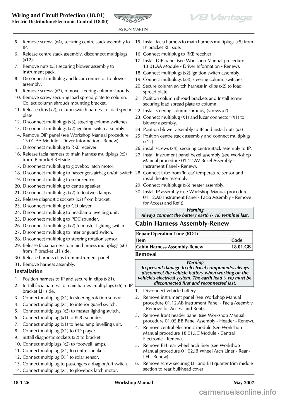
5. Remove screws (x4), securing centre stack assembly to
IP.
6. Release centre stack assembly, disconnect multiplugs (x12).
7. Remove nuts (x3) securing blower assembly to instrument pack.
8. Disconnect multiplug and lucar connector to blower assembly.
9. Remove screws (x7), remove steering column shrouds.
10. Remove screw securing load spread plate to column. Collect column shrouds mounting bracket.
11. Release clips (x2), column switch harness to load spread plate.
12. Disconnect multiplugs (x3), steering column switches.
13. Disconnect multiplugs (x2) ignition switch assembly.
14. Remove DIP panel (see Workshop Manual procedure 13.01.AA Module - Driver Information - Renew).
15. Disconnect multiplug to RKE receiver.
16. Release facia harness to main harness multiplugs (x5) from IP bracket RH side.
17. Disconnect multiplug to glovebox latch motor.
18. Disconnect multiplug to pass engers airbag on/off switch.
19. Disconnect multiplug to solar sensor.
20. Disconnect multiplug to centre speaker.
21. Disconnect multiplugs (x2) to footwell lamps.
22. Release diagnostic sockets (x2) from bracket.
23. Disconnect multiplug to CD player.
24. Disconnect multiplug to headlamp levelling unit.
25. Disconnect multiplug to PDC sounder.
26. Disconnect multiplugs (x2) to master lighting switch.
27. Disconnect multiplug to interior guard switch.
28. Disconnect multiplug to steering rotation sensor.
29. Release facia harness to main harness multiplugs (x6) from IP bracket LH side.
30. Release harness clips from instrument panel.
31. Remove harness assembly.
Installation
1. Position harness to IP and secure in clips (x21).
2. Install facia harness to main harness multiplugs (x6) to IP bracket LH side.
3. Connect multiplug (X1) to steering rotation sensor.
4. Connect multiplug (X1) to interior guard switch.
5. Connect multiplugs (x2) to master lighting switch.
6. Connect multiplug (x1) to PDC sounder.
7. Connect multiplug (x1) to headlamp levelling unit.
8. Connect multiplug (X1) to CD player.
9. install diagnostic sockets (x2) to bracket.
10. Connect multiplugs (x2) to footwell lamps.
11. Connect multiplug (X1) to centre speaker.
12. Connect multiplug (X1) to solar sensor.
13. Connect multiplug to passengers airbag on/off switch.
14. Connect multiplug (X1) to glovebox latch motor. 15. Install facia harness to main harness multiplugs (x5) from
IP bracket RH side.
16. Connect multiplug to RKE receiver.
17. Install DIP panel (see Workshop Manual procedure 13.01.AA Module - Driver Information - Renew).
18. Connect multiplugs (x2) ignition switch assembly.
19. Connect multiplugs (x3), steering column switches.
20. Secure column switch harness in clips (x2) to load spread plate.
21. Position column shroud brackets and Install screw securing load spread plate to column.
22. Install steering column shrouds, (screws x7).
23. Connect multiplug (X1) an d lucar connector (X1) to
blower assembly.
24. Position blower assembly to IP and install nuts (x3)
25. Position centre stack assembly and connect multiplugs (x12).
26. install screws (x4), securing centre stack assembly to IP.
27. Install instrument panel bezel assembly (see Workshop Manual procedure 01.12.AV Bezel Assembly -
Instrument Panel - Renew).
28. Connect tube from 'In-car' temperature sensor and install heater assembly.
29. Connect multiplugs (x6) heater assembly.
30. Install IP assembly (see Workshop Manual procedure
01.12.AB Instrument Panel - Facia Assembly - Remove
for Access and Refit).
Cabin Harness Assembly-Renew
Removal
1. Disconnect vehicle battery.
2. Remove instrument panel (see Workshop Manual procedure 01.12.AB Instrume nt Panel - Facia Assembly
- Remove for Access and Refit).
3. Remove front header panel (see Workshop Manual procedure 01.05.BB Panel Assembly - Header - Renew).
4. Remove central electronic module (see Workshop Manual procedure 18.01.LC Module - Central
Electronic - Renew).
5. Remove RH rear wheel arch liner (see Workshop Manual procedure 01.02.JB Wheel Arch Liner - Rear -
LH - Renew).
6. Remove screw securing LH and RH quarter trim middle section to rear bulkhead cover.
Warning
Always connect the battery earth (- ve) terminal last.
Repair Operation Time (ROT)
ItemCode
Cabin Harness Assembly-Renew 18.01.GB
Warning
To prevent damage to elec trical components, always
disconnect the vehicle battery when working on the
vehicle's electrical system. The earth lead (- ve) must be
disconnected first and reconnected last.
Page 751 of 947
Maintenance Schedules
Appendix & Glossary20-1-12 Workshop Manual May 2007
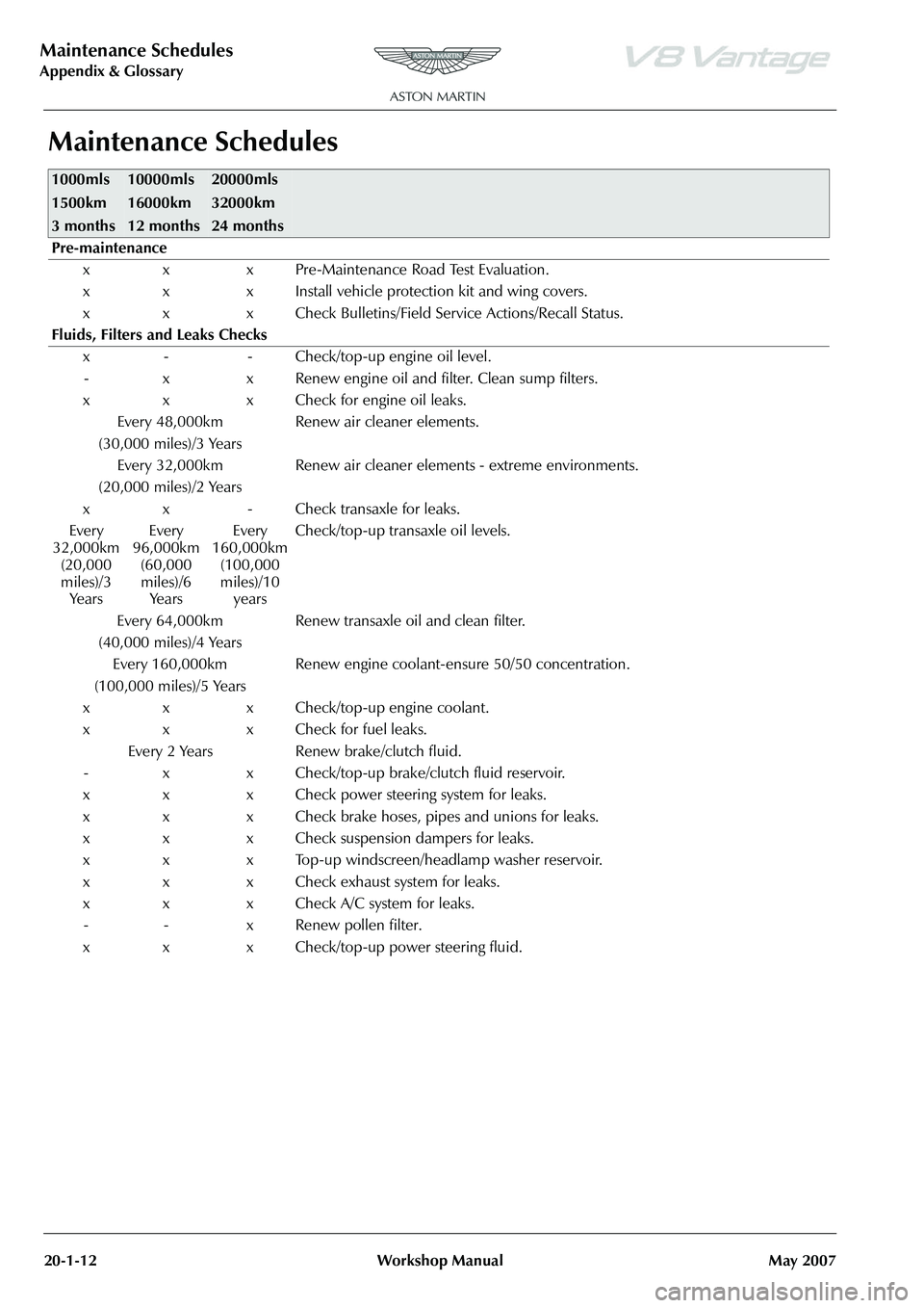
Maintenance Schedules
1000mls
1500km
3 months10000mls
16000km
12 months20000mls
32000km
24 months
Pre-maintenance
x x x Pre-Maintenance Road Test Evaluation.
x x x Install vehicle protection kit and wing covers.
x x x Check Bulletins/Field Service Actions/Recall Status.
Fluids, Filters and Leaks Checks x - - Check/top-up engine oil level.- x x Renew engine oil and filter. Clean sump filters.
x x x Check for engine oil leaks. Every 48,000km
(30,000 miles)/3 Years Renew air cleaner elements.
Every 32,000km
(20,000 miles)/2 Years Renew air cleaner elements - extreme environments.
x x - Check transaxle for leaks.
Every
32,000km (20,000
miles)/3 Ye a r s Every
96,000km (60,000
miles)/6 Ye a r s Every
160,000km (100,000
miles)/10 years Check/top-up transaxle oil levels.
Every 64,000km
(40,000 miles)/4 Years Renew transaxle oil and clean filter.
Every 160,000km
(100,000 miles)/5 Years Renew engine coolant-ensure 50/50 concentration.
x x x Check/top-up engine coolant.
x x x Check for fuel leaks. Every 2 Years Renew brake/clutch fluid.
- x x Check/top-up brake/clutch fluid reservoir.
x x x Check power steering system for leaks.
x x x Check brake hoses, pipes and unions for leaks.
x x x Check suspension dampers for leaks.
x x x Top-up windscreen/headlamp washer reservoir.
x x x Check exhaust system for leaks.
x x x Check A/C system for leaks. - - x Renew pollen filter.
x x x Check/top-up power steering fluid.
Page 752 of 947
Torque Figures
Appendix & Glossary
May 2007 Workshop Manual 20-1-13
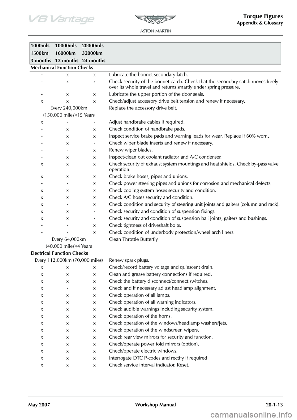
Mechanical Function Checks - x x Lubricate the bonnet secondary latch.
- x x Check security of the bonnet catch. Ch eck that the secondary catch moves freely
over its whole travel and returns smartly under spring pressure.
- x x Lubricate the upper portion of the door seals.
x x x Check/adjust accessory drive belt tension and renew if necessary. Every 240,000km
(150,000 miles)/15 Years Replace the accessory drive belt.
x - - Adjust handbrake cables if required. - x x Check condition of handbrake pads.
- x x Inspect service brake pads and warnin g leads for wear. Replace if 60% worn.
- x - Check wiper blade inserts and renew if necessary.
- - x Renew wiper blades.
- x x Inspect/clean out coolant radiator and A/C condenser.
x x x Check security of exhaust system mountings and heat shields. Check by-pass valve operation.
x x x Check brake hoses, pipes and unions. - - x Check power steering pipes and unions for corrosion and mechanical defects.
x x x Check cooling system hoses security and condition.
x x x Check A/C hoses security and condition.
x - x Check condition and security of steering unit joints and gaiters (column and rack).
x x - Check security and condition of suspension fixings.
x x - Check security and condition of susp ension ball joints, gaiters and bushings.
- - x Check tightness of driveshaft bolts.
- - x Check condition of underbody protection/wheel arch liners.
Every 64,000km
(40,000 miles)/4 Years Clean Throttle Butterfly
Electrical Function Checks Every 112,000km (70,000 miles) Renew spark plugs. x x x Check/record battery voltage and quiescent drain.
x x x Clean and grease battery connections if required.
x x x Check the battery disconnect/connect switches.
x - x Check and if necessary adjust headlamp alignment.
x x x Check operation of all lamps.
x x x Check operation of all warning indicators.
x x x Check audible warnings including security system.
x x x Check operation of the horns.
x x x Check operation of the windows/headlamp washers/jets.
x x x Check operation of the windscreen wipers.
x x x Check rear view mirrors for security and function.
x x x Check/operate power fold mirrors (option).
x x x Check/operate electric windows.
x x x Interrogate DTC P-codes and rectify if required
x x x Check service interval indicator. Reset.
1000mls
1500km
3 months10000mls
16000km
12 months20000mls
32000km
24 months
Page 938 of 947

SB-17-0298
February 2009 Page 1 of 5
SERVICE BULLETIN
To: All Dealers
For the attention of: Service Manager/After Sales Manager
Please copy to: The Dealer Principal
The Warranty Administrator
Aston Martin Technician(s)
The Parts Manager
Reference
SB-17-0298
Issued:
26 February 2009
Model: DBS, DB9, V8 and V12 Vantage
VIN Range: All
Subject: Headlamp Drying Out Procedure Page 1 of 5
Reason for this Service Bulletin
The headlamps of DBS, DB9, V8 and V12 Vantage models can get condensation on the inside surface of the lens.
If a customer complains that their vehicle has condensa tion in a headlamp, do the applicable procedure that
follows to remove the condensation.
Workshop Procedures
DBS and DB9 Vehicles
1. Turn the steering to get access to the headlamp access panel for the correct headlamp.
2. Lift the vehicle and make it safe.
3. Release the quarter-turn fastener and remove the
headlamp access panel (refer to Figure 1).
Figure 1
4. Remove the dip-beam bulb cover from the headlamp.
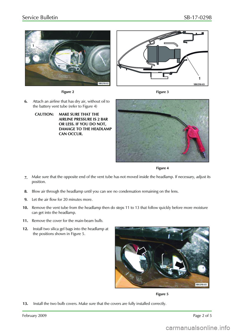
5. Install a battery vent tube (part number 1R12-372635-AA) (1) into the head lamp in the position shown in
Figure 2 and Figure 3.
Page 939 of 947
Service Bulletin SB-17-0298
February 2009 Page 2 of 5
Figure 2
1
SB0298-03
Figure 3
6. Attach an airline that has dry air, without oil to
the battery vent tube (refer to Figure 4)
CAUTION: MAKE SURE THAT THE
AIRLINE PRESSURE IS 2 BAR
OR LESS. IF YOU DO NOT,
DAMAGE TO THE HEADLAMP
CAN OCCUR.
Figure 4
7. Make sure that the opposite end of the vent tube has
not moved inside the headlamp. If necessary, adjust its
position.
8. Blow air through the headlamp until you can see no condensation remaining on the lens.
9. Let the air flow for 20 minutes more.
10. Remove the vent tube from the headlamp then do st eps 11 to 13 that follow quickly before more moisture
can get into the headlamp.
11. Remove the cover for the main-beam bulb.
12. Install two silica gel bags into the headlamp at
the positions shown in Figure 5.
Figure 5
13. Install the two bulb covers. Make sure that the covers are fully installed correctly.
Page 940 of 947

Service Bulletin SB-17-0298
February 2009 Page 3 of 5
14. Install the headlamp access panel and turn the quarter turn fastener to attach it.
15. Lower the vehicle.
16. Adjust the steering to the straight forward position.
V8 and V12 Vantage Vehicles
1. Turn the steering to get access to the headlamp access panel for the correct headlamp.
2. Lift the vehicle and make it safe.
3. Release the quarter-turn fastener an d remove the headlamp access panel.
4. Remove the two screws (1) that attach the bulb
cover (2) to the headlamp (refer to Figure 6).
Figure 6
5. Remove the bulb cover from the headlamp.
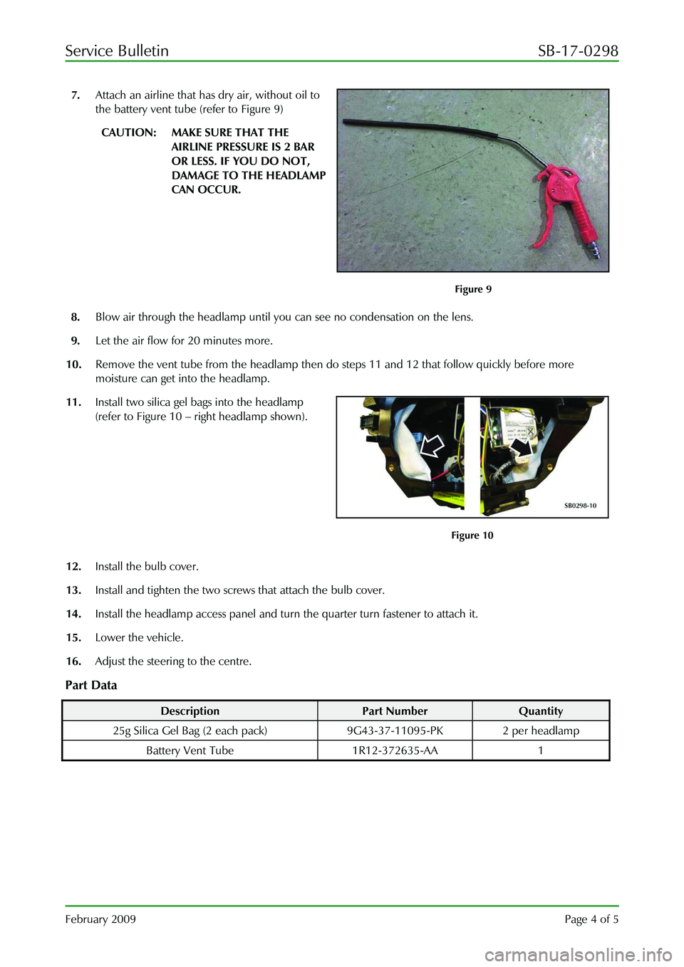
6. Install a battery vent tube (1) into the headlamp in the position shown in Figure 7 and Figure 8.
Figure 7
Figure 8
Page 941 of 947
Service Bulletin SB-17-0298
February 2009 Page 4 of 5
7. Attach an airline that has dry air, without oil to
the battery vent tube (refer to Figure 9)
CAUTION: MAKE SURE THAT THE
AIRLINE PRESSURE IS 2 BAR
OR LESS. IF YOU DO NOT,
DAMAGE TO THE HEADLAMP
CAN OCCUR.
Figure 9
8. Blow air through the headlamp until you can see no condensation on the lens.
9. Let the air flow for 20 minutes more.
10. Remove the vent tube from the headlamp then do steps 11 and 12 that follow quickly before more
moisture can get into the headlamp.
11. Install two silica gel bags into the headlamp
(refer to Figure 10 – right headlamp shown).
Figure 10
12. Install the bulb cover.
13. Install and tighten the two screws that attach the bulb cover.
14. Install the headlamp access panel and turn the quarter turn fastener to attach it.
15. Lower the vehicle.
16. Adjust the steering to the centre.
Part Data
Description Part Number Quantity
25g Silica Gel Bag (2 each pa ck) 9G43-37-11095-PK 2 per headlamp
Battery Vent Tube 1R12-372635-AA 1