oil ASTON MARTIN V8 VANTAGE 2010 Workshop Manual
[x] Cancel search | Manufacturer: ASTON MARTIN, Model Year: 2010, Model line: V8 VANTAGE, Model: ASTON MARTIN V8 VANTAGE 2010Pages: 947, PDF Size: 43.21 MB
Page 910 of 947

Aston Martin V8 Vantage2009MY OBDII Documentation 4.7L Aston Martin Confidential
Component P CodesMalfunction Strategy
Description Malfunction Criteria
(Fault) Fault condition
(Internal labels) Threshold Value
(Fault condition) Entry conditions Entry conditions values Filter Time to
log DTCPump relay P0947 Pump relay connected GNDPump relay Short circuit to GND The asic UH04 inside the TCU
detects the fault and communicate it to the uP
Driver output current > th3 during valve on phase th3= 3.7A
NOT (Cranking) 200ms
Clutch system P186D Clutch or actuator or valve damagedClutch not opening before gear
shifting Clutch not open in a timeout timeout = 500ms (Gear shifting in
progress) AND
(Clutch opening
Gear Box system P1734 Mechanical or hydraulic problemGear Box. Disengage failed
(mechanical causes) Gear not disengaged in a timeout timeout = 500ms (Gear shifting phase)
AND (disengage phase)
Gear Box system P1701 Mechanical or hydraulic problemGear Box. Wrong gear
engagement The gear which is going to be
engaged is not the requested one (Gear shifting phase)
Hydraulic circuit P0868 Hydraulic leakage Hydraulic circuit. Pressure low Comparison between sensor pressure signal and threshold = f(oil temperature)
pressure < th Th= 25 bar @ -30°C
Th= 40 bar @120°C linear interpolation (Engine ON) AND
NOT (cranking) 200ms
Power grounds P1710 Power grounds. Disconnection both ground pins Power grounds. Disconnection
both ground pins The diagnosis is based on the batter
y
voltage modification during the
activation of the clutch electrovalve. Ubatt < Ubatt0 - DltUbatt Ubatt0 = Ubatt before
starting the testDltUbatt = 2,5V Wake-up phase
ASM OBD
628/04/2008
Page 924 of 947
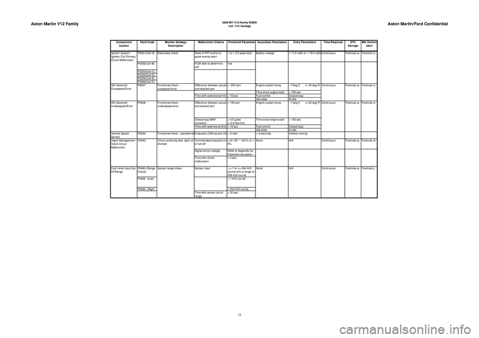
Aston Martin V12 Family
2009 MY V12 Family EOBDincl. V12 Vantage
Aston Martin/Ford Confidential
Component/ System Fault Code Monitor Strategy
Description Malfunction Criteria Threshold Parameter Secondary Parameters Entry Parameters Time Required DTC
StorageMIL Illumin-
ation
P0351(Coil A) Ratio of PIP events to
spark events seen 1 to 1 (To pass test) Battery voltage
> 11.0 volts or < 18.0 volts Continuous Footnote a) Footnote c)
P0352(Coil B) PCM able to determine
coil Yes
P0353(Coil C)
P0354(Coil D)
P0355(Coil E)
P0356(Coil F) Functional check -
overspeed error Difference between actual
and desired rpm> -200 rpm
Engine coolant temp -7 deg C (> 20 deg F)
Time since engine start > 100 sec
Time with solenoid at limit > 15 sec Fuel controlClosed loop
Idle state At idle
Difference between actual
and desired rpm > 100 rpm
Engine coolant temp -7 deg C (> 20 deg F)
Closed loop MAF
correction > 4.5 g/sec
(> 0.6 lbs/min)Time since engine start > 100 sec
Time with solenoid at limit > 10 sec Fuel controlClosed loop
Idle state At idle
Vehicle Speed
Sensor P0500 Functional check - operational Evaluates CAN source VS > 3 mph
> 4 secondsVehicle moving
Commanded dutycycle on
or full-off >=0.135 * 100 % or =
0%None
N/A Continuous Footnote a) Footnote e)
Signal circuit voltage Refer to Appendix for threshold calculation
Time with circuit
malfunction > 5 sec
P0460 (Range
Check) Sensor input
<= 7 or >= 254 A/D
counts w/in a range of
256 A/D counts
P0462 (Low) < 7 A/D counts
P0463 (High) > 254 A/D counts
Time with sensor out of
range > 30 sec N/A
Continuous Footnote a) Footnote j)
Fuel Level Input Out
Of Range Sensor range check
None
Vapor Management
Valve Circuit
Malfunction
P0443 Circuit continuity test, open or
shorted Footnote a) Footnote c)
IAC Solenoid
Underspeed Error P0506 Functional check -
underspeed error Continuous
IAC Solenoid
Overspeed Error
P0507
Continuous Footnote a) Footnote c)
Ignition System-
Ignition Coil Primary
Circuit Malfunction
Rationality check
13
Page 935 of 947
System
Component
P Codes (AML)
Malfunction Strategy Description
Malfunction Criteria
(Fault)
Fault condition
(Internal labels)
Threshold Value
(Fault condition)
Entry conditions
Entry conditions values
Filter Time to log DTC (AML)
EMS controlled MIL Illumination
(AML)
(V vs Temp
)App A,
Ref 1
1
30mS 50mS
2 DTC
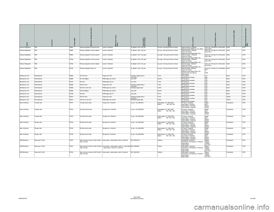
Mechatronic Unit Shift Solenoid P0985SV1 S/C Gnd Target max.7.6% Hardware register fault or
umv1_RLo <7.6%
FET turned on
lowside drivers unlockedTrue
True20mS
2 DTC
Mechatronic Unit Shift Solenoid P0986SV1 S/C Battery PWM target max. 92.4% umv1_Rhi>92.4%FET turned on
lowside drivers unlocked True
True20mS
2 DTC
Mechatronic Unit Shift Solenoid P0770SV1 O/C PWM target max 7.6 umv1_Rlo<7.6%FET turned on
lowside drivers unlocked True
True20mS
2 DTC
Mechatronic Unit Shift Solenoid P0998SV2 S/C Gnd Target max.7.6% Hardware register fault or
umv2_RLo <7.6%
FET turned on
lowside drivers unlockedTrue
True20mS
2 DTC
Mechatronic Unit Shift Solenoid P0998SV2 O/C or S/C Gnd PWM target max. 92.4% Hardware register fault=100%FET turned on
lowside drivers unlocked True
True20mS
2 DTC
Mechatronic Unit Shift Solenoid P0999SV2 S/C Battery PWM target max. 92.4% umv2_Rhi>92.4%FET turned on
lowside drivers unlocked True
True20mS
2 DTC
Mechatronic Unit Shift Solenoid P2706SV2 O/C PWM target max 7.6 umv2_Rlo<7.6%FET turned on
lowside drivers unlocked True
True20mS
2 DTC
Mechatronic Unit Park Solenoid P2814SV3 S/C Gnd Target max.7.6% Hardware register fault or
umv3_RLo <7.6%
FET turned on
lowside drivers unlockedTrue
True100mS
2 DTC
Mechatronic Unit Park Solenoid P2814SV3 O/C or S/C Gnd PWM target max. 92.4% Hardware register fault=100%FET turned on
lowside drivers unlocked True
True100mS
2 DTC
Gear monitoring 1st Gear ratio P07311st Gear slip too high 1st gear slip > threshold nd_syn > KL_NDUWG1Outputspeed 0.0 1000 2000
Ndsyn> 400 400 640 ATF temp > threshold
output speed > threshold
Engine Speed > threshold
Turbine Speed > threshold0DegC
0rpm
550rpm
416rpm3 Symptoms
2 DTC
Gear monitoring 2nd gear ratio P07322nd Gear slip too high 2nd gear slip > threshold nd_syn > KL_NDUWG2Outputspeed 0.0 1000 3300
Ndsyn> 400 400 640 ATF temp > threshold
output speed > threshold
Engine Speed > threshold
Turbine Speed > threshold0DegC
0rpm
550rpm
416rpm3 Symptoms
2 DTC
Gear monitoring 3rd gear ratio P07333rd Gear slip too high 3rd gear slip > threshold nd_syn > KL_NDUWG3Output speed 0.0 1000 5000
Ndsyn> 400 400 640 ATF temp > threshold
output speed > threshold
Engine Speed > threshold
Turbine Speed > threshold0DegC
0rpm
550rpm
416rpm3 Symptoms
2 DTC
Gear monitoring 4th gear ratio P07344th Gear slip too high 4th gear slip > threshold nd_syn > KL_NDUWG4Output speed 0.0 1000 6500
Ndsyn> 400 400 640 ATF temp > threshold
output speed > threshold
Engine Speed > threshold
Turbine Speed > threshold0DegC
0rpm
550rpm
416rpm3 Symptoms
2 DTC
Gear monitoring 5th gear ratio P07355th Gear slip too high 5th gear slip > threshold nd_syn > KL_NDUWG5Output speed 0.0 1000 8160
Ndsyn> 400 400 640 ATF temp > threshold
output speed > threshold
Engine Speed > threshold
Turbine Speed > threshold0DegC
0rpm
550rpm
416rpm3 Symptoms
2 DTC
Gear monitoring 6th gear ratio P07296th Gear slip too high 6th gear slip > threshold nd_syn > KL_NDUWG6Output speed 0.0 1000 8160
Ndsyn> 400 400 640 ATF temp > threshold
output speed > threshold
Engine Speed > threshold
Turbine Speed > threshold0DegC
0rpm
550rpm
416rpm3 Symptoms
2 DTC
Shift Monitoring Gear load 1-2 shift P0781Gear load error during 1-2 shift. Clutch C
does not close. (input speed - output speed x ratio) > threshold ND_TSUEA12Z
>400rpmoutputspeed > threshold
transmission oil temperature > threshold
engine speed
range position 256rpm
10DegC
1200rpm
no P, R, N5 Symptoms
2 DTC
Shift Monitoring Gear load 1-2 shift P0781Gear load error during 1-2 shift. Clutch D
does not open.
(input speed - output speed x ratio
) (t) - (input speed
- output speed x ratio) (0) < threshold ND_TUNSUEB
<30rpmoutput speed > threshold
transmission oil temperature > threshold
engine speed
range position 256rpm
10DegC
1200rpm
no P, R, N5 Symptoms
2 DTC
Shift Monitoring Gear load 2-3 shift P0782Gear load error during 2-3 shift. Clutch C
does not close. (input speed - output speed x ratio) > threshold ND_TSUEA23Z
>300rpmoutput speed > threshold
transmission oil temperature > threshold
engine speed
range position 256rpm
10DegC
1200rpm
no P, R, N5 Symptoms
2 DTC
8ASXV05.9VH1 Aston Martin
Auto Gearbox Summary Jan 2008
Page 936 of 947
System
Component
P Codes (AML)
Malfunction Strategy Description
Malfunction Criteria
(Fault)
Fault condition
(Internal labels)
Threshold Value
(Fault condition)
Entry conditions
Entry conditions values
Filter Time to log DTC (AML)
EMS controlled MIL Illumination
(AML)
(input speed - output speed x ratio
) (t) - (input speed
- output speed x ratio) (0) < threshold ND_TUNSUEB
<30rpmoutput speed > threshold
transmission oil temperature > threshold
engine speed
range position 256rpm
10DegC
1200rpm
no P, R, N5 Symptoms
2 DTC
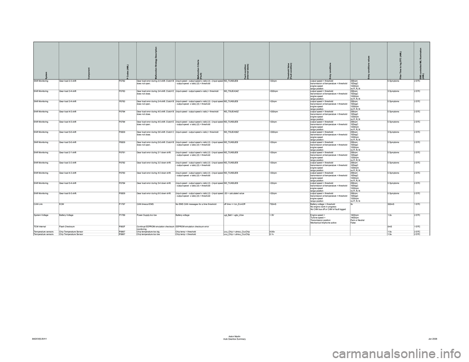
Shift Monitoring Gear load 4-5 shift P0784Gear load error during 4-5 shift. Clutch B
does not close. (input speed - output speed x ratio) > threshold ND_TSUEA45Z
>300rpmoutput speed > threshold
transmission oil temperature > threshold
engine speed
range position 256rpm
10DegC
1200rpm
no P, R, N5 Symptoms
2 DTC
Shift Monitoring Gear load 4-5 shift P0784Gear load error during 4-5 shift. Clutch E
does not open.
(input speed - output speed x ratio
) (t) - (input speed
- output speed x ratio) (0) < threshold ND_TUNSUEB
<30rpmoutput speed > threshold
transmission oil temperature > threshold
engine speed
range position 256rpm
10DegC
1200rpm
no P, R, N5 Symptoms
2 DTC
Shift Monitoring Gear load 5-6 shift P0829Gear load error during 5-6 shift. Clutch C
does not close. (input speed - output speed x ratio) > threshold ND_TSUEA56Z
>300rpmoutput speed > threshold
transmission oil temperature > threshold
engine speed
range position 256rpm
10DegC
1200rpm
no P, R, N5 Symptoms
2 DTC
Shift Monitoring Gear load 5-6 shift P0829Gear load error during 5-6 shift. Clutch B
does not open.
(input speed - output speed x ratio
) (t) - (input speed
- output speed x ratio) (0) < threshold ND_TUNSUEB
<30rpmoutput speed > threshold
transmission oil temperature > threshold
engine speed
range position 256rpm
10DegC
1200rpm
no P, R, N5 Symptoms
2 DTC
Shift Monitoring Gear load 2-1 shift P0781Gear load error during 2-1 down shift.
(input speed - output speed x ratio
) (t) - (input speed
- output speed x ratio) (0) < threshold ND_TUNSUEB
<30rpmoutput speed > threshold
transmission oil temperature > threshold
engine speed
range position 256rpm
10DegC
1200rpm
no P, R, N5 Symptoms
2 DTC
Shift Monitoring Gear load 3-2 shift P0782Gear load error during 3-2 down shift.
(input speed - output speed x ratio
) (t) - (input speed
- output speed x ratio) (0) < threshold ND_TUNSUEB
<30rpmoutput speed > threshold
transmission oil temperature > threshold
engine speed
range position 256rpm
10DegC
1200rpm
no P, R, N5 Symptoms
2 DTC
Shift Monitoring Gear load 4-3 shift P0783Gear load error during 4-3 down shift.
(input speed - output speed x ratio
) (t) - (input speed
- output speed x ratio) (0) < threshold ND_TUNSUEB
<30rpmoutput speed > threshold
transmission oil temperature > threshold
engine speed
range position 256rpm
10DegC
1200rpm
no P, R, N5 Symptoms
2 DTC
Shift Monitoring Gear load 5-4 shift P0784Gear load error during 5-4 down shift.
(input speed - output speed x ratio
) (t) - (input speed
- output speed x ratio) (0) < threshold ND_TUNSUEB
<30rpmoutput speed > threshold
transmission oil temperature > threshold
engine speed
range position 256rpm
10DegC
1200rpm
no P, R, N5 Symptoms
2 DTC
Shift Monitoring Gear load 6-5 shift. P0829Gear load error during 6-5 down shift.
(input speed - output speed x ratio
) (t) - (input speed
- output speed x ratio) (0) < threshold -30 > calculated value
<30rpmoutput speed > threshold
transmission oil temperature > threshold
engine speed
range position 256rpm
10DegC
1200rpm
no P, R, N5 Symptoms
2 DTC
CAN Link ECM P1797CAN timeout EMS No EMS CAN messages for a time threshold off time >= tcn_EcmOff 750mSBattery voltage > threshold
No engine crank in progress
No CAN bus off or CAN lvl fault logged 9v
500mS1 DTC
System Voltage Battery Voltage P1789Power Supply too low Battery voltage ugt_Batt < ugts_Ulow< 9VEngine speed >
Turbine speed >
Transmission position
Mechanical limphome active 1400rpm
1400rpm
Park or Neutral
False1.0s
2 DTC
TCM Internal Flash Checksum P062FContinual EEPROM emulation checksum
monitoring EEPROM emulation checksum error
0mS1 DTC
Temperature sensors Chip Temperature Sensor P0667 Chip temperature too big Chip temp > threshold ucu_Chip > utmso_CcuChip4.95v 1.5s2 DTC
Temperature sensors Chip Temperature Sensor P0667 Chip temperature too low Chip temp < threshold ucu_Chip < utmsu_CcuChip0.1v 1.5s2 DTC
8ASXV05.9VH1 Aston Martin
Auto Gearbox Summary Jan 2008
Page 939 of 947
Service Bulletin SB-17-0298
February 2009 Page 2 of 5
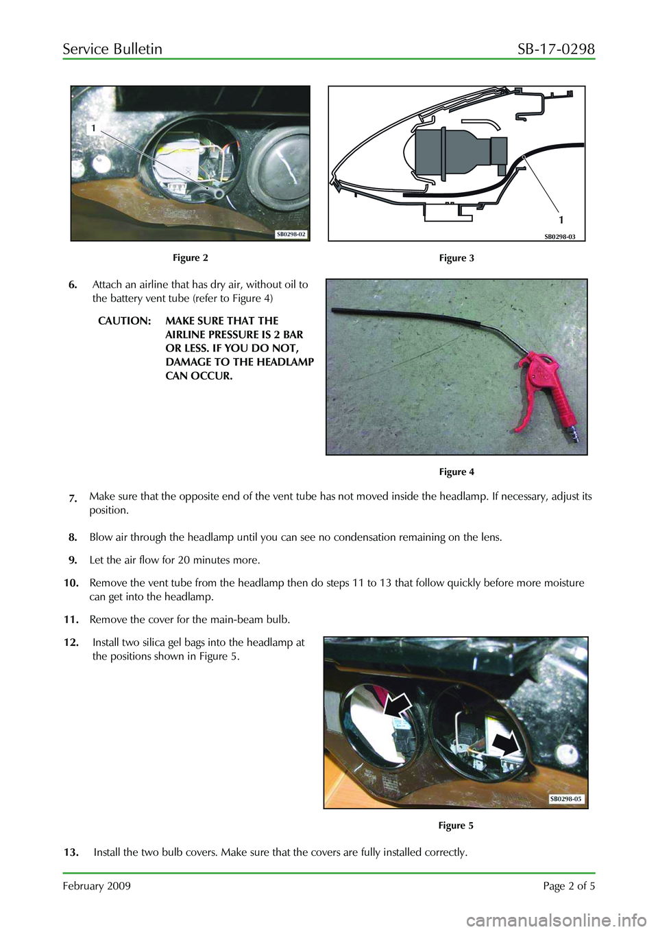
Figure 2
1
SB0298-03
Figure 3
6. Attach an airline that has dry air, without oil to
the battery vent tube (refer to Figure 4)
CAUTION: MAKE SURE THAT THE
AIRLINE PRESSURE IS 2 BAR
OR LESS. IF YOU DO NOT,
DAMAGE TO THE HEADLAMP
CAN OCCUR.
Figure 4
7. Make sure that the opposite end of the vent tube has
not moved inside the headlamp. If necessary, adjust its
position.
8. Blow air through the headlamp until you can see no condensation remaining on the lens.
9. Let the air flow for 20 minutes more.
10. Remove the vent tube from the headlamp then do st eps 11 to 13 that follow quickly before more moisture
can get into the headlamp.
11. Remove the cover for the main-beam bulb.
12. Install two silica gel bags into the headlamp at
the positions shown in Figure 5.
Figure 5
13. Install the two bulb covers. Make sure that the covers are fully installed correctly.
Page 941 of 947
Service Bulletin SB-17-0298
February 2009 Page 4 of 5
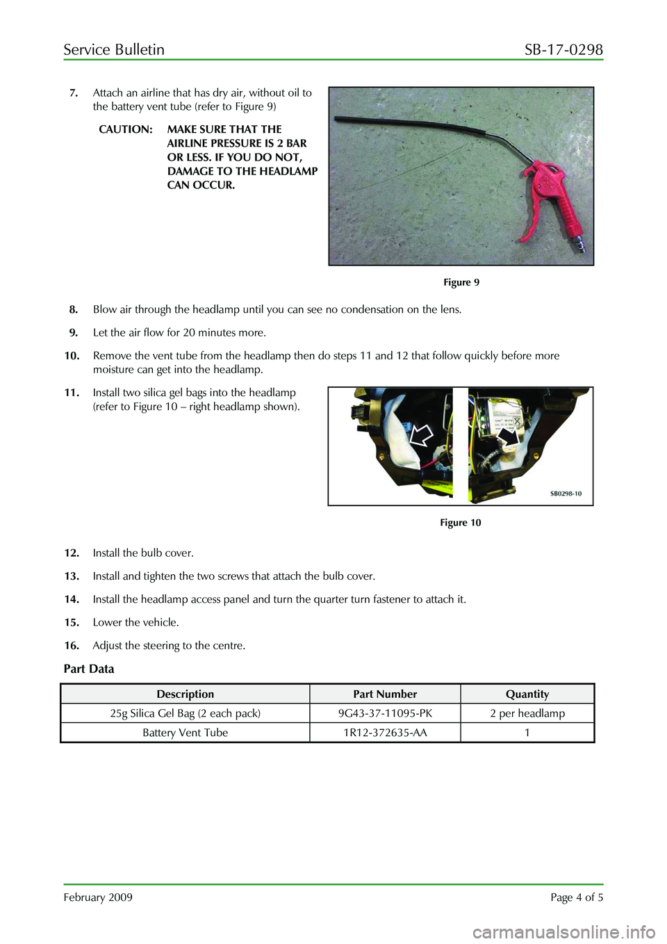
7. Attach an airline that has dry air, without oil to
the battery vent tube (refer to Figure 9)
CAUTION: MAKE SURE THAT THE
AIRLINE PRESSURE IS 2 BAR
OR LESS. IF YOU DO NOT,
DAMAGE TO THE HEADLAMP
CAN OCCUR.
Figure 9
8. Blow air through the headlamp until you can see no condensation on the lens.
9. Let the air flow for 20 minutes more.
10. Remove the vent tube from the headlamp then do steps 11 and 12 that follow quickly before more
moisture can get into the headlamp.
11. Install two silica gel bags into the headlamp
(refer to Figure 10 – right headlamp shown).
Figure 10
12. Install the bulb cover.
13. Install and tighten the two screws that attach the bulb cover.
14. Install the headlamp access panel and turn the quarter turn fastener to attach it.
15. Lower the vehicle.
16. Adjust the steering to the centre.
Part Data
Description Part Number Quantity
25g Silica Gel Bag (2 each pa ck) 9G43-37-11095-PK 2 per headlamp
Battery Vent Tube 1R12-372635-AA 1
Page 945 of 947
Service Bulletin SB0286V2
December 2009 Page 3 of 5
Note: The location of the water leak can be difficult to find.
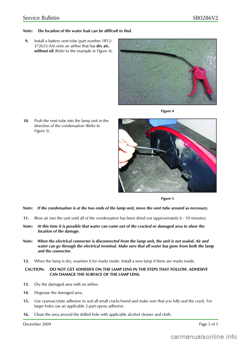
9. Install a battery vent tube (part number 1R12-
372635-AA) onto an airline that has dry air,
without oil (Refer to the example in Figure 4).
Figure 4
10. Push the vent tube into the lamp unit in the
direction of the condensation (Refer to
Figure 5).
Figure 5
Note: If the condensation is at the two ends of the la mp unit, move the vent tube around as necessary.
11. Blow air into the unit until all of the condensati on has been dried out (approximately 6 - 10 minutes).
Note: At this time it is possible that water can come out of the cracked or damaged area to show the
location of the damage.
Note: When the electrical connector is disconnected from the lamp unit, the unit is not sealed. Air and
water can go through the electrical terminal. Make sure that all water has gone from both the lamp
and the connector.
12. When the lamp is dry, examine it for marks inside. Install a new lamp if there are marks inside.
CAUTION: DO NOT GET ADHESIVE ON THE LAMP LENS IN THE STEPS THAT FOLLOW. ADHESIVE
CAN DAMAGE THE SURFACE OF THE LAMP LENS.
13. Dry the damaged area with an airline.
14. Degrease the damaged area.
15. Use cyanoacrylate adhesive to seal all small cracks fo und and make sure that you fully seal the crack. For
larger holes use an applicab le 2-part epoxy adhesive.
16. Clean the area around the drilled hole with applicable alcohol cleaner and cloth.