engine oil level ASTON MARTIN V8 VANTAGE 2010 Owner's Manual
[x] Cancel search | Manufacturer: ASTON MARTIN, Model Year: 2010, Model line: V8 VANTAGE, Model: ASTON MARTIN V8 VANTAGE 2010Pages: 947, PDF Size: 43.21 MB
Page 549 of 947
Manual Transmission (07.03)
Transmission (07.00)
Issue 5, January 2010 Workshop Manual 7-3-33
43. Install the tunnel reinforcement plate.
44. Install and torque the eight bolts that attach the tunnel reinforcement plate to the body.
45. Install floor heatshield.
46. Install and tighten the four bolts that attach the floor heat shield to the body.
47. Install the exhaust front mount.
48. Clean the component mating faces.
49. Apply an applicable sealant to the component mating faces.
50. Install the exhaust centre pipe.
51. Install and tighten the four bolts that attach the exhaust centre pipe to the exhaust front mount.
52. Put the clamps into position on the exhaust pipes.
53. Loosely install the four bolts that attach the exhaust centre pipe to the rear silencer.
54. Align the exhaust assembly.
55. Tighten the two clamps that attach the exhaust centre pipe to the catalytic converters.
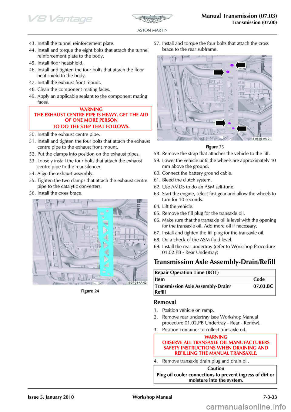
56. Install the cross brace.
Figure 24
57. Install and torque the four bolts that attach the cross brace to the rear subframe.
Figure 25
58. Remove the strap that attaches the vehicle to the lift.
59. Lower the vehicle until the wheels are approximately 10 mm above the ground.
60. Connect the battery ground cable.
61. Bleed the clutch system.
62. Use AMDS to do an ASM self-tune.
63. Start the engine, select first gear and allow the wheels to turn for 10 seconds.
64. Lift the vehicle.
65. Remove the fill plug for the transaxle oil.
66. Make sure that the transaxle oil is level with the opening for the transaxle oil. Add more oil if necessary.
67. Install and tighten the fill plug for the transaxle oil.
68. Do a check of the ASM fluid level.
69. Install the rear undertray (refer to Workshop Procedure 01.02.PB - Rear Undertray)
Removal
1. Position vehicle on ramp.
2. Remove rear undertray (see Workshop Manual procedure 01.02.PB Undertray - Rear - Renew).
3. Position container to collect transaxle oil.
4. Remove transaxle drain plug and drain oil.
WA R N I N G
THE EXHAUST CENTRE PIPE IS HEAVY. GET THE AID
OF ONE MORE PERSON
TO DO THE STEP THAT FOLLOWS.
Repair Operation Time (ROT)
Page 602 of 947
Steering Gear (11.01)
Steering (11.00)
Issue 5, January 2010 Workshop Manual 11-1-3
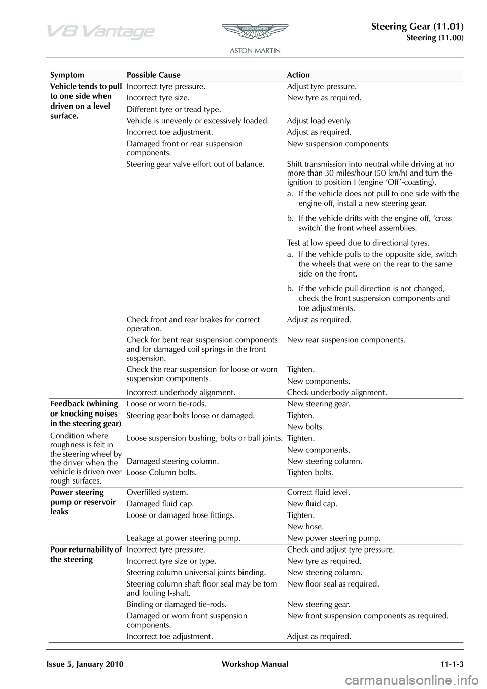
Vehicle tends to pull
to one side when
driven on a level
surface. Incorrect tyre pressure. Adjust tyre pressure.
Incorrect tyre size.
Different tyre or tread type.
New tyre as required.
Vehicle is unevenly or excessively loaded. Adjust load evenly.
Incorrect toe adjustment. Adjust as required.
Damaged front or rear suspension
components. New suspension components.
Steering gear valve effort out of balance. Shift transmission into neutral while driving at no more than 30 miles/hour (50 km/h) and turn the
ignition to position I (engine ‘Off’-coasting).
a. If the vehicle does not pull to one side with the
engine off, install a new steering gear.
b. If the vehicle drifts with the engine off, ‘cross switch’ the front wheel assemblies.
Test at low speed due to directional tyres.
a. If the vehicle pulls to the opposite side, switch the wheels that were on the rear to the same
side on the front.
b. If the vehicle pull direction is not changed, check the front suspension components and
toe adjustments.
Check front and rear brakes for correct
operation. Adjust as required.
Check for bent rear suspension components
and for damaged coil springs in the front
suspension. New rear suspension components.
Check the rear suspension for loose or worn
suspension components. Tighten.
New components.
Incorrect underbody alignment. Check underbody alignment.
Feedback (whining
or knocking noises
in the steering gear)
Condition where
roughness is felt in
the steering wheel by
the driver when the
vehicle is driven over
rough surfaces. Loose or worn tie-rods. New steering gear.
Steering gear bolts loose or damaged. Tighten.
New bolts.
Loose suspension bushing , bolts or ball joints. Tighten.
New components.
Damaged steering column.
Loose Column bolts. New steering column.
Tighten bolts.
Power steering
pump or reservoir
leaks Overfilled system. Correct fluid level.
Damaged fluid cap. New fluid cap.
Loose or damaged hose fittings. Tighten.
New hose.
Leakage at power steering pump. New power steering pump.
Poor returnability of
the steering Incorrect tyre pressure. Check
and adjust tyre pressure.
Incorrect tyre size or ty pe. New tyre as required.
Steering column universal joints binding . New steering column.
Steering column shaft floor seal may be torn
and fouling I-shaft. New floor seal as required.
Binding or damaged tie-rods. New steering gear.
Damaged or worn front suspension
components. New front suspension components as required.
Incorrect toe adjustment. Adjust as required.
SymptomPossible CauseAction
Page 605 of 947
Power Steering (11.02)
Steering (11.00)11-2-2 Workshop Manual Issue 5, January 2010
Maintenance
Power Steering System - Bleed
Procedure
1. Do a check of the fluid level in the PAS fluid reservoir. Add fluid if necessary.
2. Start the engine and let it idle for 20 seconds.
3. Operate the steering fully to the left and then the right through three cycles.
4. Stop the engine.
5. Wait for five minutes then do a check of the fluid level in the PAS fluid reservoir again.
6. Add fluid if necessary.
7. Install the PAS fluid reservoir cap.
Power Steering Pump-Renew
Removal
1. Remove A/C compressor (see Workshop Manual procedure 03.05.BE Compre ssor - Air Conditioning -
Renew).
2. Coolant drain (see Workshop Manual procedure 03.03.AD Coolant - Drain & Refill).
3. Remove PAS fluid from reservoir.
4. Disconnect HP union from PAS pump pipe.
5. Remove bolt P-clip suction hose to body.
6. Remove bolt (x1) HP pump pipe to engine.
7. Remove bolts (x3) PAS pump to engine.
8. Disconnect bottom hose and move aside.
9. Unclip (x1) harness from cylinder head for access.
10. Manouvre pump forward and up.
11. Disconnect suction hose (cut off clip) and remove pump.
12. Remove HP union pipe from pump (mark position on
pump).
Installation
1. Install HP union pipe to pump (align correctly), fit new O-ring.
2. Install pump to vehicle connect suction pipe to PAS pump, align timing marks and fit new clip.
3. Manouvre pump into position.
4. Install bolts (x3) PAS pump to engine (torque).
5. Install bolt (x1) HP pump pipe to engine (torque).
6. Connect bottom hose.
7. Clip (x1) harness from cylinder head for access. 8. Install bolt P-clip suction hose to body (torque).
9. Connect HP union to PAS pump pipe, replace O-ring
(torque).
10. Coolant refill (see Workshop Manual procedure 03.03.AD Coolant - Drain & Refill).
11. Install A/C compressor (see Workshop Manual procedure 03.05.BE Compre ssor - Air Conditioning -
Renew).
12. Top-up PAS fluid.
13. Start and run engine, operate steering lock to lock x2.
14. Top-up PAS fluid.
Power Assisted Steering (PAS) Rack -
Remove and Install
Removal
1. Disconnect the battery ground cable.
2. Remove the front undertray (refer to Workshop Manual Procedure 01.02.NB - Front Undertray).
3. Remove the front wheels and tyres (refer to Workshop Manual Procedure 04.04.ED - Wheel and Tyre - Pair).
4. Remove the front right side wheel-arch liner (refer to Workshop Manual Procedure 01.02.GB - Front Right
Side Wheel-Arch Liner).
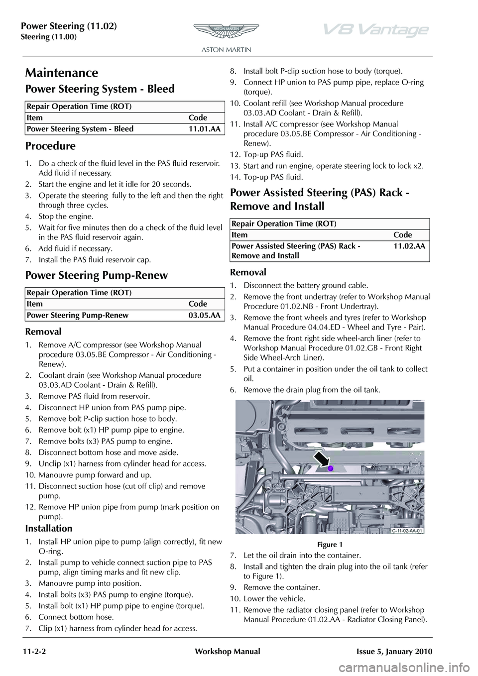
5. Put a container in position under the oil tank to collect oil.
6. Remove the drain plug from the oil tank.
Figure 1
7. Let the oil drain into the container.
8. Install and tighten the drain plug into the oil tank (refer to Figure 1).
9. Remove the container.
10. Lower the vehicle.
11. Remove the radiator closing panel (refer to Workshop Manual Procedure 01.02.AA - Radiator Closing Panel).
Repair Operation Time (ROT)
Repair Operation Time (ROT)
Repair Operation Time (ROT)
ItemCode
Power Assisted Steering (PAS) Rack -
Remove and Install 11.02.AA
Page 614 of 947
Power Steering (11.02)
Steering (11.00)
Issue 5, January 2010 Workshop Manual 11-2-11
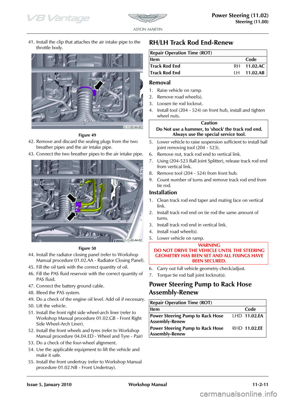
41. Install the clip that attaches the air intake pipe to the throttle body.
Figure 49
42. Remove and discard the sealing plugs from the two breather pipes and the air intake pipe.
43. Connect the two breather pipes to the air intake pipe.
Figure 50
44. Install the radiator closing panel (refer to Workshop Manual procedure 01.02.AA - Radiator Closing Panel).
45. Fill the oil tank with the correct quantity of oil.
46. Fill the PAS fluid reservoir with the correct quantity of
PAS fluid.
47. Connect the battery ground cable.
48. Bleed the PAS system.
49. Do a check of the engine oi l level. Add oil if necessary.
50. Lift the vehicle.
51. Install the front right side wheel-arch liner (refer to Workshop Manual procedure 01.02.GB - Front Right
Side Wheel-Arch Liner).
52. Install the front wheels and tyres (refer to Workshop Manual procedure 04.04.ED - Wheel and Tyre - Pair)
53. Do a check of the four-wheel alignment.
54. Use the applicable equipment to lift the vehicle and make it safe.
55. Install the front undertray (refer to Workshop Manual procedure 01.02.NB - Front Undertray).
RH/LH Track Rod End-Renew
Removal
1. Raise vehicle on ramp.
2. Remove road wheel(s).
3. Loosen tie rod locknut.
4. Install tool (204 - 524) on front hub, install and tighten
wheel nuts.
5. Lower vehicle to raise suspension sufficient to install ball joint removing tool (204 - 523).
6. Remove nut, track rod end to vertical link.
7. Using (204-523 Ball Joint Sp litter), release track rod end
from vertical link.
8. Remove tool (204 - 524) from front hub.
9. Count number of turns and remove track rod end from tie rod.
Installation
1. Clean track rod end taper and mating face on vertical link.
2. Install track rod end on tie rod the same amount of turns.
3. Install track rod end in vertical link.
4. Install road wheel(s).
5. Lower vehicle on ramp.
6. Carry out full vehicle geometry check/adjust.
7. Torque tie rod ball joint locknut(s).
Power Steering Pump to Rack Hose
Assembly-Renew
Repair Operation Time (ROT)
Repair Operation Time (ROT)
Page 654 of 947
Instrument Cluster (13.01)
Information, Gauge and Warning (13.00)
May 2007 Workshop Manual 13-1-3
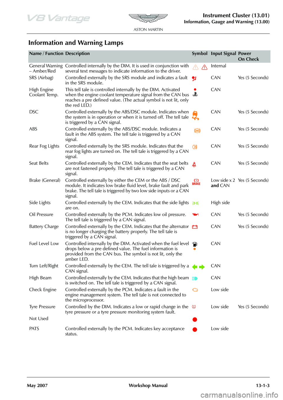
Information and Warning Lamps
Name / FunctionDescriptionSymbolInput SignalPower
On Check
General Warning
– Amber/Red Controlled internally by the DIM. It is used in conjunction with
several text messages to indicate information to the driver. Internal
SRS (Airbag) Controlled externally by the SRS module and indicates a fault in the SRS module. CAN Yes (5 Seconds)
High Engine
Coolant Temp. This tell tale is controlled internally by the DIM. Activated
when the engine coolant temperature signal from the CAN bus
reaches a pre defined value. (The
actual symbol is not lit, only
the red LED.) CAN
DSC Controlled externally by the ABS/DSC module. Indicates when the system is in operation or when it is turned off. The tell tale
is triggered by a CAN signal. CAN Yes (5 Seconds)
ABS Controlled externally by th e ABS/DSC module. Indicates a
fault in the ABS system. The tell tale is triggered by a CAN
signal. CAN Yes (5 Seconds)
Rear Fog Lights Controlled externally by the SRS module. Indicates that the
rear fog lights are turned on. The tell tale is triggered by a CAN
signal. CAN Yes (5 Seconds)
Seat Belts Controlled externally by the CEM. Indicates that the seat belts are not fastened properly. The tell tale is triggered by a CAN
signal. CAN Yes (5 Seconds)
Brake (General) Controlled externally by either the CEM or the ABS / DSC module. It indicates low brake fluid level, brake fault and park
brake. The tell tale is triggered by two low side inputs or a CAN
signal. Low side x 2
and
CAN Ye s ( 5 S e c o n d s )
Side Lights Controlled externally by th e CEM. Indicates that the side lights
are on. High side
Oil Pressure Controlled exte rnally by the PCM. Indicates low oil pressure.
The tell tale is triggered by a CAN signal. CAN Yes (5 Seconds)
Battery Charge Controlled externally by th e CEM. Indicates that the alternator
is no longer charging the battery properly. The tell tale is
triggered by a CAN signal. CAN Yes (5 Seconds)
Fuel Level Low Controlled internally by the DIM. Activated when the fuel level drops below a pre defined value. The fuel information is
provided from the CAN bus. The symbol is not lit, only the
amber LED. CAN
Turn Left/Right Controlled externally by th e CEM. The tell tale is triggered by a
CAN signal. CAN
High Beam Controlled externally by the CEM. Indicates that the high beam is switched on. The tell tale is triggered by a CAN signal. CAN
Check Engine Controlled externally by the PCM. Indicates a fault in the engine management system. The te ll tale is not connected to
the microprocessor. Low side
Tyre Pressure Controlled by the DIM. In dicates a low or rapid change in the
tyre pressure or a tyre pressure monitoring system fault. Low side Yes (5 Seconds)
Not Used
PATS Controlled externally by the PCM. Indicates key acceptance status. Low side
Page 751 of 947
Maintenance Schedules
Appendix & Glossary20-1-12 Workshop Manual May 2007
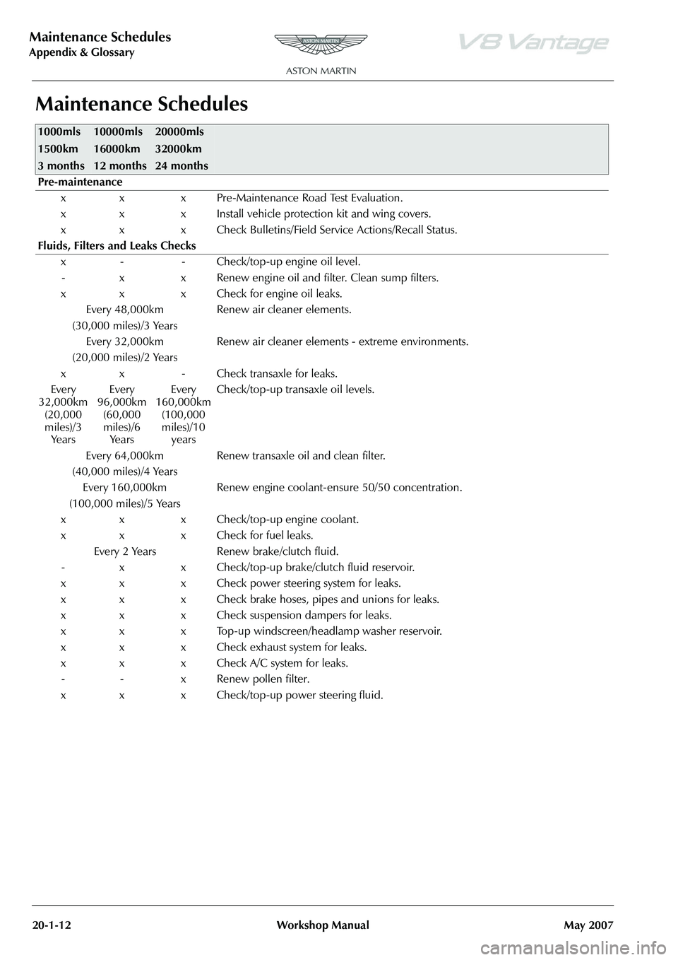
Maintenance Schedules
1000mls
1500km
3 months10000mls
16000km
12 months20000mls
32000km
24 months
Pre-maintenance
x x x Pre-Maintenance Road Test Evaluation.
x x x Install vehicle protection kit and wing covers.
x x x Check Bulletins/Field Service Actions/Recall Status.
Fluids, Filters and Leaks Checks x - - Check/top-up engine oil level.- x x Renew engine oil and filter. Clean sump filters.
x x x Check for engine oil leaks. Every 48,000km
(30,000 miles)/3 Years Renew air cleaner elements.
Every 32,000km
(20,000 miles)/2 Years Renew air cleaner elements - extreme environments.
x x - Check transaxle for leaks.
Every
32,000km (20,000
miles)/3 Ye a r s Every
96,000km (60,000
miles)/6 Ye a r s Every
160,000km (100,000
miles)/10 years Check/top-up transaxle oil levels.
Every 64,000km
(40,000 miles)/4 Years Renew transaxle oil and clean filter.
Every 160,000km
(100,000 miles)/5 Years Renew engine coolant-ensure 50/50 concentration.
x x x Check/top-up engine coolant.
x x x Check for fuel leaks. Every 2 Years Renew brake/clutch fluid.
- x x Check/top-up brake/clutch fluid reservoir.
x x x Check power steering system for leaks.
x x x Check brake hoses, pipes and unions for leaks.
x x x Check suspension dampers for leaks.
x x x Top-up windscreen/headlamp washer reservoir.
x x x Check exhaust system for leaks.
x x x Check A/C system for leaks. - - x Renew pollen filter.
x x x Check/top-up power steering fluid.
Page 885 of 947
AML EOBD System Operation Summary
Rory O’Curry Aston Martin Lagonda CONFIDENTIAL 1 May 2009
[email protected] AML EOBD Monitors 07 ROC.doc Page 40 of 43
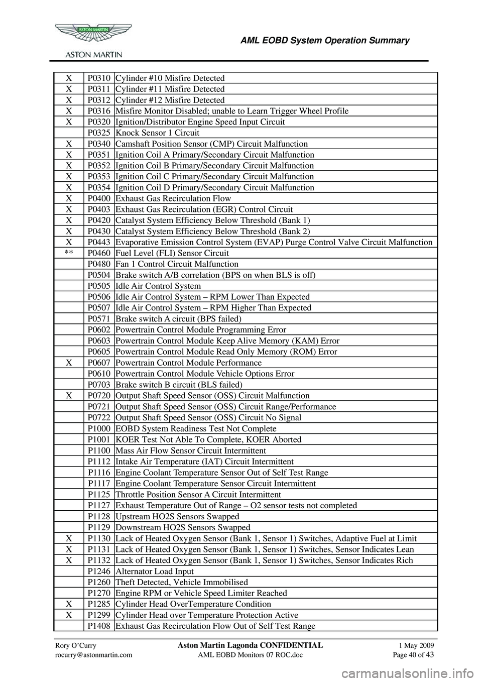
X P0310 Cylinder #10 Misfire Detected
X P0311 Cylinder #11 Misfire Detected
X P0312 Cylinder #12 Misfire Detected
X P0316 Misfire Monitor Disabled; unable to Learn Trigger Wheel Profile
X P0320 Ignition/Distributor Engine Speed Input Circuit
P0325 Knock Sensor 1 Circuit
X P0340 Camshaft Position Sens or (CMP) Circuit Malfunction
X P0351 Ignition Coil A Primary/Secondary Circuit Malfunction
X P0352 Ignition Coil B Primary/Secondary Circuit Malfunction
X P0353 Ignition Coil C Primary/Secondary Circuit Malfunction
X P0354 Ignition Coil D Primary/Secondary Circuit Malfunction
X P0400 Exhaust Gas Recirculation Flow
X P0403 Exhaust Gas Recirculation (EGR) Control Circuit
X P0420 Catalyst System Efficiency Below Threshold (Bank 1)
X P0430 Catalyst System Efficiency Below Threshold (Bank 2)
X P0443 Evaporative Emission Control System (EVAP) Purge Control Valve Circuit Malfunction
** P0460 Fuel Level (FLI) Sensor Circuit
P0480 Fan 1 Control Circuit Malfunction
P0504 Brake switch A/B correlation (BPS on when BLS is off)
P0505 Idle Air Control System
P0506 Idle Air Control System – RPM Lower Than Expected
P0507 Idle Air Control System – RPM Higher Than Expected
P0571 Brake switch A circuit (BPS failed)
P0602 Powertrain Control Module Programming Error
P0603 Powertrain Control Module Keep Alive Memory (KAM) Error
P0605 Powertrain Control Module Read Only Memory (ROM) Error
X P0607 Powertrain Control Module Performance
P0610 Powertrain Control Module Vehicle Options Error
P0703 Brake switch B circuit (BLS failed)
X P0720 Output Shaft Speed Sensor (OSS) Circuit Malfunction
P0721 Output Shaft Speed Sensor (OSS) Circuit Range/Performance
P0722 Output Shaft Speed Sensor (OSS) Circuit No Signal
P1000 EOBD System Readiness Test Not Complete
P1001 KOER Test Not Able To Complete, KOER Aborted
P1100 Mass Air Flow Sensor Circuit Intermittent
P1112 Intake Air Temperature (IAT) Circuit Intermittent
P1116 Engine Coolant Temperature Sensor Out of Self Test Range
P1117 Engine Coolant Temperature Sensor Circuit Intermittent
P1125 Throttle Position Sensor A Circuit Intermittent
P1127 Exhaust Temperature Out of Range – O2 sensor tests not completed
P1128 Upstream HO2S Sensors Swapped
P1129 Downstream HO2S Sensors Swapped
X P1130 Lack of Heated Oxygen Sensor (Bank 1, Sensor 1) Switches, Adaptive Fuel at Limit
X P1131 Lack of Heated Oxygen Sensor (Bank 1, Sensor 1) Switches, Sensor Indicates Lean
X P1132 Lack of Heated Oxygen Sensor (Bank 1, Sensor 1) Switches, Sensor Indicates Rich
P1246 Alternator Load Input
P1260 Theft Detected, Vehicle Immobilised
P1270 Engine RPM or Vehicle Speed Limiter Reached
X P1285 Cylinder Head OverTemperature Condition
X P1299 Cylinder Head over Temperature Protection Active
P1408 Exhaust Gas Recirculation Flow Out of Self Test Range
Page 900 of 947
Aston Martin V8 Vantage 2009 MY EOBD DocumentationAston Martin/Ford Confidential
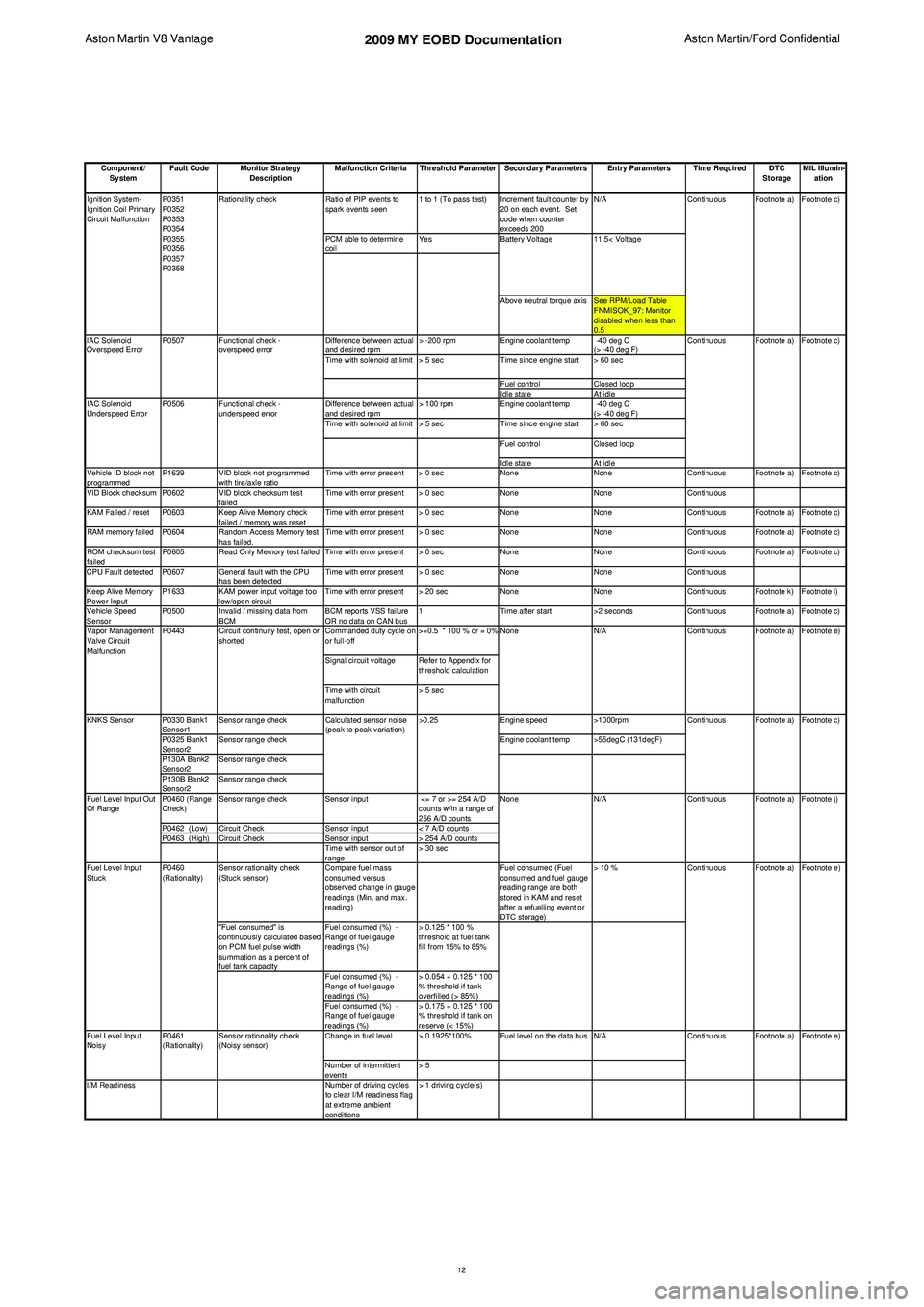
Component/ System Fault Code Monitor Strategy
Description Malfunction Criteria Threshold Parameter Secondary Parameters Entry Parameters Time Required DTC
StorageMIL Illumin-
ation
Ratio of PIP events to
spark events seen 1 to 1 (To pass test) Increment fault counter by
20 on each event. Set
code when counter
exceeds 200 N/A
PCM able to determine
coil Yes
Above neutral torque axis See RPM/Load Table FNMISOK_97: Monitor
disabled when less than
0.5
Difference between actual
and desired rpm > -200 rpm
Engine coolant temp -40 deg C
(> -40 deg F)
Time with solenoid at limit > 5 sec Time since engine start > 60 sec
Fuel control Closed loop
Idle state At idle
Difference between actual
and desired rpm > 100 rpm
Engine coolant temp -40 deg C
(> -40 deg F)
Time with solenoid at limit > 5 sec Time since engine start > 60 sec
Fuel control Closed loop
Idle state At idle
Vehicle ID block not
programmed P1639 VID block not programmed
with tire/axle ratio Time with error present > 0 sec
NoneNoneContinuous Footnote a) Footnote c)
VID Block checksum P0602 VID block checksum test failedTime with error present > 0 sec
NoneNoneContinuous
KAM Failed / reset P0603 Keep Alive Memory check failed / memory was resetTime with error present > 0 sec
NoneNoneContinuous Footnote a) Footnote c)
RAM memory failed P0604 Random Access Memory test has failed.Time with error present > 0 sec
NoneNoneContinuous Footnote a) Footnote c)
ROM checksum test
failed P0605 Read Only Memory test failed Time with error present > 0 sec
NoneNoneContinuous Footnote a) Footnote c)
CPU Fault detected P0607 General fault with the CPU has been detectedTime with error present > 0 sec
NoneNoneContinuous
Keep Alive Memory
Power Input P1633 KAM power input voltage too
low/open circuit Time with error present > 20 sec
NoneNoneContinuous Footnote k) Footnote i)
Vehicle Speed
Sensor P0500 Invalid / missing data from
BCM BCM reports VSS failure
OR no data on CAN bus1
Time after start >2 secondsContinuous Footnote a) Footnote c)
Commanded duty cycle on
or full-off >=0.5 * 100 % or = 0%
Signal circuit voltage Refer to Appendix for threshold calculation
Time with circuit
malfunction > 5 sec
P0330 Bank1
Sensor1 Sensor range check
Engine speed>1000rpm
P0325 Bank1
Sensor2 Sensor range check
Engine coolant temp >55degC (131degF)
P130A Bank2
Sensor2 Sensor range check
P130B Bank2
Sensor2 Sensor range check
P0460 (Range
Check) Sensor range check
Sensor input <= 7 or >= 254 A/D
counts w/in a range of
256 A/D counts
P0462 (Low) Circuit Check Sensor input< 7 A/D counts
P0463 (High) Circuit Check Sensor input> 254 A/D counts
Time with sensor out of
range > 30 sec
Sensor rationality check
(Stuck sensor) Compare fuel mass
consumed versus
observed change in gauge
readings (Min. and max.
reading) Fuel consumed (Fuel
consumed and fuel gauge
reading range are both
stored in KAM and reset
after a refuelling event or
DTC storage)> 10 %
"Fuel consumed" is
continuously calculated based
on PCM fuel pulse width
summation as a percent of
fuel tank capacity Fuel consumed (%) -
Range of fuel gauge
readings (%)
> 0.125 * 100 %
threshold at fuel tank
fill from 15% to 85%
Fuel consumed (%) -
Range of fuel gauge
readings (%) > 0.054 + 0.125 * 100
% threshold if tank
overfilled (> 85%)
Fuel consumed (%) -
Range of fuel gauge
readings (%) > 0.175 + 0.125 * 100
% threshold if tank on
reserve (< 15%)
Change in fuel level > 0.1925*100% Fuel level on the data bus N/A
Number of intermittent
events > 5
I/M Readiness Number of driving cycles
to clear I/M readiness flag
at extreme ambient
conditions > 1 driving cycle(s) Footnote e)
Footnote a)
Footnote c)
Footnote a) Footnote j) Footnote e)
Fuel Level Input
Noisy Continuous Footnote a)
Continuous Footnote a)
P0461
(Rationality) Sensor rationality check
(Noisy sensor)
Fuel Level Input
Stuck
P0460
(Rationality) Continuous
N/A Continuous
Calculated sensor noise
(peak to peak variation)
>0.25
KNKS Sensor
Fuel Level Input Out
Of Range NoneFootnote a) Footnote e)
Vapor Management
Valve Circuit
Malfunction P0443 Circuit continuity test, open or
shorted None
N/A Continuous
11.5< Voltage
Ignition System-
Ignition Coil Primary
Circuit Malfunction
IAC Solenoid
Underspeed Error P0507
P0506
Functional check -
overspeed error
Functional check -
underspeed error
IAC Solenoid
Overspeed Error
Footnote a) Footnote c)
Continuous
P0351
P0352
P0353
P0354
P0355
P0356
P0357
P0358
Rationality check
Continuous Footnote a) Footnote c)
Battery Voltage
12
Page 924 of 947
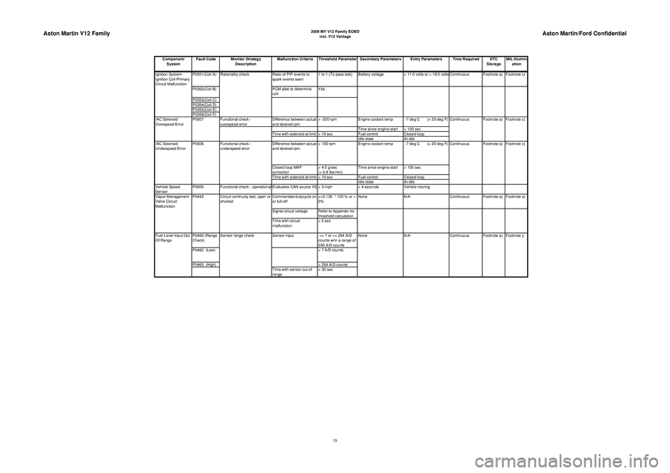
Aston Martin V12 Family
2009 MY V12 Family EOBDincl. V12 Vantage
Aston Martin/Ford Confidential
Component/ System Fault Code Monitor Strategy
Description Malfunction Criteria Threshold Parameter Secondary Parameters Entry Parameters Time Required DTC
StorageMIL Illumin-
ation
P0351(Coil A) Ratio of PIP events to
spark events seen 1 to 1 (To pass test) Battery voltage
> 11.0 volts or < 18.0 volts Continuous Footnote a) Footnote c)
P0352(Coil B) PCM able to determine
coil Yes
P0353(Coil C)
P0354(Coil D)
P0355(Coil E)
P0356(Coil F) Functional check -
overspeed error Difference between actual
and desired rpm> -200 rpm
Engine coolant temp -7 deg C (> 20 deg F)
Time since engine start > 100 sec
Time with solenoid at limit > 15 sec Fuel controlClosed loop
Idle state At idle
Difference between actual
and desired rpm > 100 rpm
Engine coolant temp -7 deg C (> 20 deg F)
Closed loop MAF
correction > 4.5 g/sec
(> 0.6 lbs/min)Time since engine start > 100 sec
Time with solenoid at limit > 10 sec Fuel controlClosed loop
Idle state At idle
Vehicle Speed
Sensor P0500 Functional check - operational Evaluates CAN source VS > 3 mph
> 4 secondsVehicle moving
Commanded dutycycle on
or full-off >=0.135 * 100 % or =
0%None
N/A Continuous Footnote a) Footnote e)
Signal circuit voltage Refer to Appendix for threshold calculation
Time with circuit
malfunction > 5 sec
P0460 (Range
Check) Sensor input
<= 7 or >= 254 A/D
counts w/in a range of
256 A/D counts
P0462 (Low) < 7 A/D counts
P0463 (High) > 254 A/D counts
Time with sensor out of
range > 30 sec N/A
Continuous Footnote a) Footnote j)
Fuel Level Input Out
Of Range Sensor range check
None
Vapor Management
Valve Circuit
Malfunction
P0443 Circuit continuity test, open or
shorted Footnote a) Footnote c)
IAC Solenoid
Underspeed Error P0506 Functional check -
underspeed error Continuous
IAC Solenoid
Overspeed Error
P0507
Continuous Footnote a) Footnote c)
Ignition System-
Ignition Coil Primary
Circuit Malfunction
Rationality check
13