hand brake ASTON MARTIN V8 VANTAGE 2010 Owner's Manual
[x] Cancel search | Manufacturer: ASTON MARTIN, Model Year: 2010, Model line: V8 VANTAGE, Model: ASTON MARTIN V8 VANTAGE 2010Pages: 947, PDF Size: 43.21 MB
Page 456 of 947
Road Wheels and Tyres (04.04)
Suspension (04.00)4-4-6 Workshop Manual May 2007
Ty r e D a m a g e
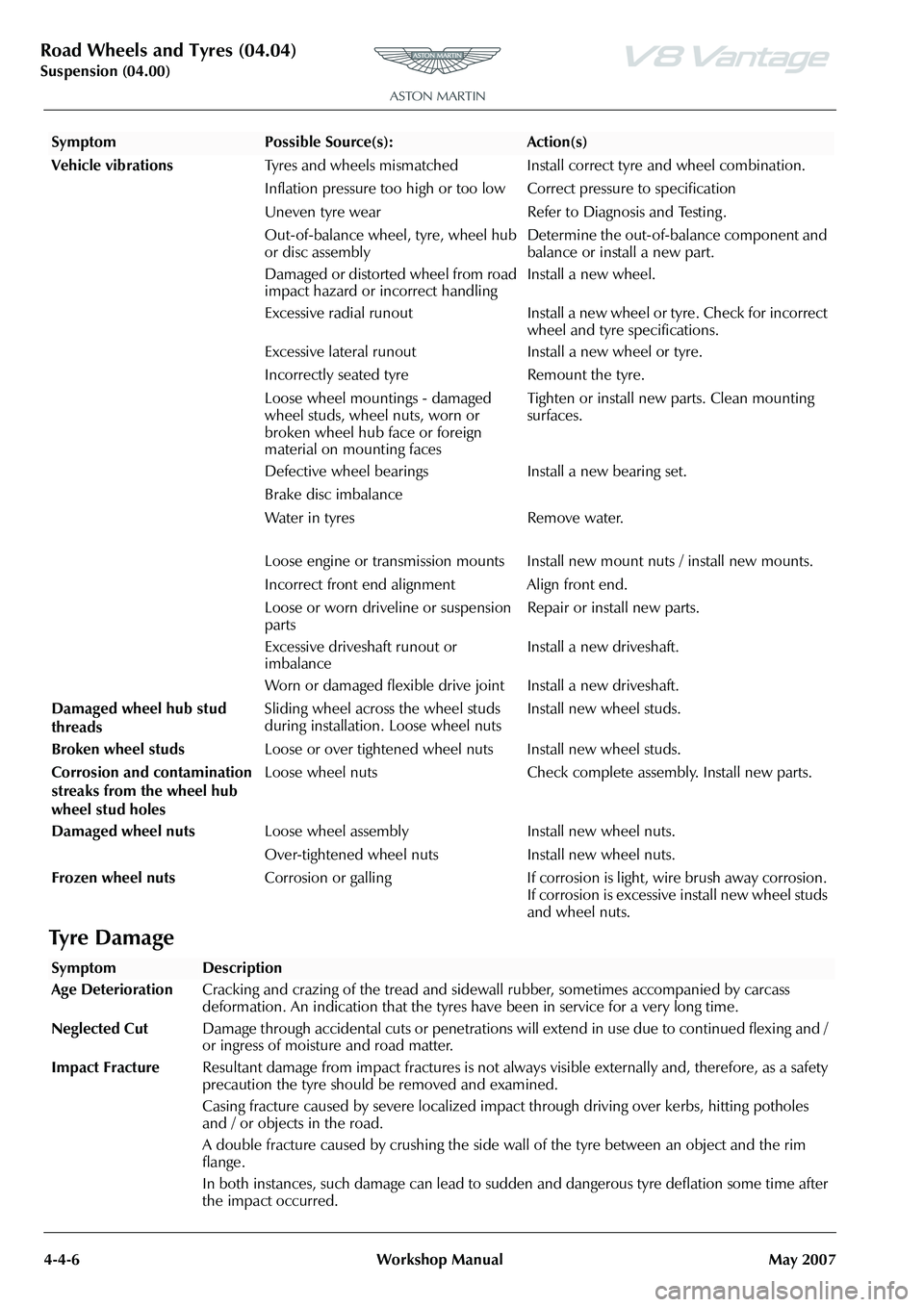
Vehicle vibrations Tyres and wheels mismatched Install correct tyre and wheel combination.
Inflation pressure too high or too lo w Correct pressure to specification
Uneven tyre wear Refer to Diagnosis and Testing .
Out-of-balance wheel, tyre, wheel hub
or disc assembly Determine the out-of-balance component and
balance or install a new part.
Damaged or distorted wheel from road
impact hazard or incorrect handling Install a new wheel.
Excessive radial runout Install a new wheel or tyre. Check for incorrect wheel and tyre specifications.
Excessive lateral runout Install a new wheel or tyre.
Incorrectly seated tyre Remount the tyre.
Loose wheel mountings - damaged
wheel studs, wheel nuts, worn or
broken wheel hub face or foreign
material on mounting faces Tighten or install new parts. Clean mounting
surfaces.
Defective wheel bearings Install a new bearing set.
Brake disc imbalance
Water in tyres Remove water.
Loose engine or transmission mounts Install new mount nuts / install new mounts.
Incorrect front end alignment Align front end.
Loose or worn driveline or suspension
parts Repair or install new parts.
Excessive driveshaft runout or
imbalance Install a new driveshaft.
Worn or damaged flexible drive joint Install a new driveshaft.
Damaged wheel hub stud
threads Sliding wheel across the wheel studs
during installation. Loose wheel nuts
Install new wheel studs.
Broken wheel studs Loose or over tightened wheel nuts Install new wheel studs.
Corrosion and contamination
streaks from the wheel hub
wheel stud holes Loose wheel nuts Check complete assembly. Install new parts.
Damaged wheel nuts Loose wheel assembly Install new wheel nuts.
Over-tightened wheel nuts Install new wheel nuts.
Frozen wheel nuts Corrosion or galling If corrosion is light, wire brush away corrosion.
If corrosion is excessive install new wheel studs
and wheel nuts.
SymptomPossible Source(s):Action(s)
SymptomDescription
Age Deterioration Cracking and crazing of the tread and side wall rubber, sometimes accompanied by carcass
deformation. An indication that the tyres have been in service for a very long time.
Neglected Cut Damage through accidental cuts or penetrations will extend in use due to continued flexing and /
or ingress of moisture and road matter.
Impact Fracture Resultant damage from impact fractures is not always visible externally and, therefore, as a safety
precaution the tyre should be removed and examined.
Casing fracture caused by severe localized impact through driving over kerbs, hitting potholes
and / or objects in the road.
A double fracture caused by crushing the side wall of the tyre between an object and the rim
flange.
In both instances, such damage can lead to sudd en and dangerous tyre deflation some time after
the impact occurred.
Page 473 of 947
Version 6, March 2010 Workshop Manual 6-3-1
Brake System (06.00)
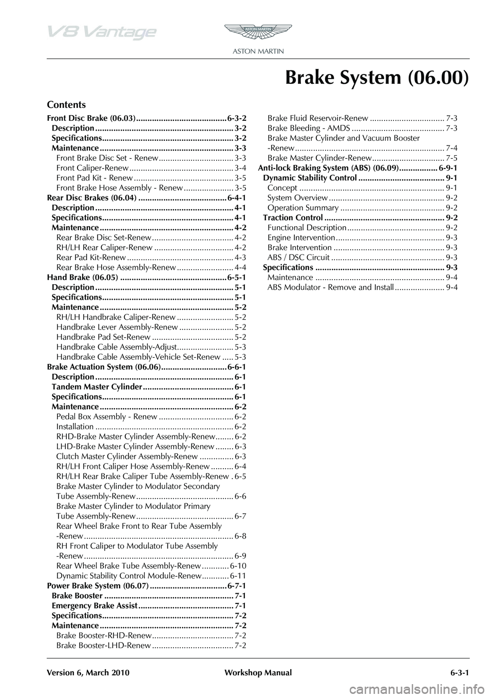
Contents
Front Disc Brake (06.03)........................................ 6-3-2Description ............................................................. 3-2
Specifications.......................................................... 3-2
Maintenance ........................................................... 3-3Front Brake Disc Set - Renew ................................. 3-3
Front Caliper-Renew .............................................. 3-4
Front Pad Kit - Renew ............................................ 3-5
Front Brake Hose Assembly - Renew ...................... 3-5
Rear Disc Brakes (06.04) ....................................... 6-4-1 Description ............................................................. 4-1
Specifications.......................................................... 4-1
Maintenance ........................................................... 4-2Rear Brake Disc Set-Renew .................................... 4-2
RH/LH Rear Caliper-Renew ................................... 4-2
Rear Pad Kit-Renew ............................................... 4-3
Rear Brake Hose Assembly-Renew ......................... 4-4
Hand Brake (06.05) ................ ............................... 6-5-1
Description ............................................................. 5-1
Specifications.......................................................... 5-1
Maintenance ........................................................... 5-2 RH/LH Handbrake Caliper-Re new ......................... 5-2
Handbrake Lever Assembly-Renew ........................ 5-2
Handbrake Pad Set-Renew .................................... 5-2
Handbrake Cable Assembly-Adjust......................... 5-3
Handbrake Cable Assembly-Vehicle Set-Renew ..... 5-3
Brake Actuation System (06.06)............................. 6-6-1 Description ............................................................. 6-1
Tandem Master Cylinder ........................................ 6-1
Specifications.......................................................... 6-1
Maintenance ........................................................... 6-2Pedal Box Assembly - Renew ................................. 6-2
Installation ............................................................. 6-2
RHD-Brake Master Cylinder Assembly-Renew........ 6-2
LHD-Brake Master Cylinder Assembly-Renew ........ 6-3
Clutch Master Cylinder Assembly-Renew ............... 6-3
RH/LH Front Caliper Hose Assembly-Renew .......... 6-4
RH/LH Rear Brake Caliper Tube Assembly-Renew . 6-5
Brake Master Cylinder to Modulator Secondary
Tube Assembly-Renew ........................................... 6-6
Brake Master Cylinder to Modulator Primary
Tube Assembly-Renew ........................................... 6-7
Rear Wheel Brake Front to Rear Tube Assembly
-Renew .................................................................. 6-8
RH Front Caliper to Modulator Tube Assembly
-Renew .................................................................. 6-9
Rear Wheel Brake Tube Assembly-Renew ............ 6-10
Dynamic Stability Control Module-Renew............ 6-11
Power Brake System (06.07) .................................. 6-7-1 Brake Booster ......................................................... 7-1
Emergency Brake Assist .......................................... 7-1
Specifications.......................................................... 7-2
Maintenance ........................................................... 7-2Brake Booster-RHD-Renew.................................... 7-2
Brake Booster-LHD-Renew .................................... 7-2 Brake Fluid Reservoir-Renew ................................. 7-3
Brake Bleeding - AMDS ......................................... 7-3
Brake Master Cylinder and Vacuum Booster
-Renew .................................................................. 7-4
Brake Master Cylinder-Renew ................................ 7-5
Anti-lock Braking System (ABS) (06.09)................. 6-9-1 Dynamic Stability Control ...................................... 9-1Concept ................................................................ 9-1
System Overview ................................................... 9-2
Operation Summary .............................................. 9-2
Traction Control ..................................................... 9-2 Functional Description ........................................... 9-2
Engine Intervention ................................................ 9-3
Brake Intervention ................................................. 9-3
ABS / DSC Circuit .................................................. 9-3
Specifications ......................................................... 9-3 Maintenance ......................................................... 9-4
ABS Modulator - Remove and Install ...................... 9-4
Page 474 of 947

Front Disc Brake (06.03)
Brake Systems (06.00)6-3-2 Workshop Manual Version 6, March 2010
Brake Systems (06.00)
Front Disc Brake (06.03)
Description
The front, four piston, brak e caliper is attached to the
vertical link with two bolts. The caliper is a monobloc
assembly. The steel brake discs are ventilated and grooved.
They are attached to the hub by two attachment bolts.
The two-pairs of opposed pistons operate directly on the
brake pads that are installed one each side of the disc.
Specifications
Oils/Greases
Brake Fluid Castrol Response SuperDOT 4 (Not silicon based brake fluid)
Brake pads
New pad thickness 9.4 mm
Minimum lining
thickness 2.5 mm
Torque Figures
DescriptionNm.lb. / ft.
Brake Hose Unions 22 16.5
Brake Hose Bracket to
Body 9 6.6
Brake Caliper to Vertical
Link 20 + 66°-70° 15 + 66°-70°
Handbrake Caliper to
Vertical Link 15 +90°-94° 11.5 + 90°-94°
Brake Disc Screws 10.5 8
Page 479 of 947
Rear Disc Brakes (06.04)
Brake system (06.00)
May 2007 Workshop Manual 6-4-1
Brake system (06.00)
Rear Disc Brakes (06.04)
Description
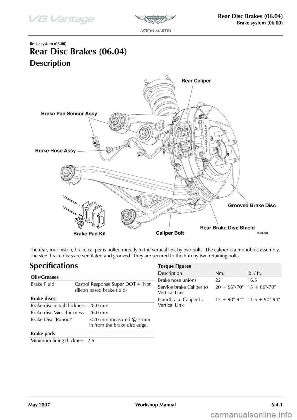
The rear, four piston, brake caliper is bolted directly to the ve rtical link by two bolts. The caliper is a monobloc assembly.
The steel brake discs are ventilated and grooved. Th ey are secured to the hub by two retaining bolts.
Specifications
06-04-001Caliper BoltRear Caliper
Brake Hose Assy
Brake Pad Kit
Brake Pad Sensor Assy
Rear Brake Disc ShieldGrooved Brake Disc
Oils/Greases
Brake Fluid Castrol Response Super DOT 4 (Not
silicon based brake fluid)
Brake pads
Minimum lining thickness 2.5
Torque Figures
DescriptionNm.lb. / ft.
Brake hose unions 22 16.5
Service brake Caliper to
Vertical Link 20 + 66°-70° 15 + 66°-70°
Handbrake Caliper to
Vertical Link 15 + 90°-94° 11.5 + 90°-94°
Page 480 of 947
Rear Disc Brakes (06.04)
Brake system (06.00)6-4-2 Workshop Manual May 2007
Maintenance
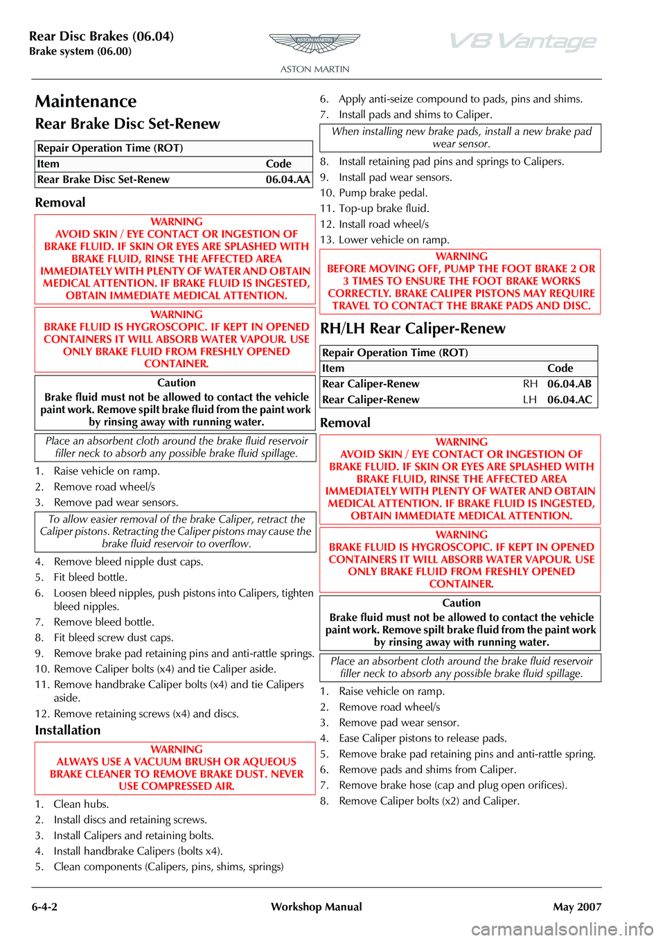
Rear Brake Disc Set-Renew
Removal
1. Raise vehicle on ramp.
2. Remove road wheel/s
3. Remove pad wear sensors.
4. Remove bleed nipple dust caps.
5. Fit bleed bottle.
6. Loosen bleed nipples, push pistons into Calipers, tighten bleed nipples.
7. Remove bleed bottle.
8. Fit bleed screw dust caps.
9. Remove brake pad retaining pins and anti-rattle springs.
10. Remove Caliper bolts (x4) and tie Caliper aside.
11. Remove handbrake Caliper bolts (x4) and tie Calipers aside.
12. Remove retaining screws (x4) and discs.
Installation
1. Clean hubs.
2. Install discs and retaining screws.
3. Install Calipers and retaining bolts.
4. Install handbrake Ca lipers (bolts x4).
5. Clean components (Caliper s, pins, shims, springs)6. Apply anti-seize compound to pads, pins and shims.
7. Install pads and shims to Caliper.
8. Install retaining pad pins
and springs to Calipers.
9. Install pad wear sensors.
10. Pump brake pedal.
11. Top-up brake fluid.
12. Install road wheel/s
13. Lower vehicle on ramp.
RH/LH Rear Caliper-Renew
Removal
1. Raise vehicle on ramp.
2. Remove road wheel/s
3. Remove pad wear sensor.
4. Ease Caliper pistons to release pads.
5. Remove brake pad retaining pins and anti-rattle spring.
6. Remove pads and shims from Caliper.
7. Remove brake hose (cap and plug open orifices).
8. Remove Caliper bolts (x2) and Caliper.
Repair Operation Time (ROT)
When installing new brake pads, install a new brake pad wear sensor.
WAR NI NG
BEFORE MOVING OFF, PUMP THE FOOT BRAKE 2 OR
3 TIMES TO ENSURE THE FOOT BRAKE WORKS
CORRECTLY. BRAKE CALIPER PISTONS MAY REQUIRE TRAVEL TO CONTACT THE BRAKE PADS AND DISC.
Repair Operation Time (ROT)
ItemCode
Rear Caliper-Renew RH06.04.AB
Rear Caliper-Renew LH06.04.AC
WAR NI NG
AVOID SKIN / EYE CONTACT OR INGESTION OF
BRAKE FLUID. IF SKIN OR EYES ARE SPLASHED WITH BRAKE FLUID, RINSE THE AFFECTED AREA
IMMEDIATELY WITH PLENTY OF WATER AND OBTAIN
MEDICAL ATTENTION. IF BR AKE FLUID IS INGESTED,
OBTAIN IMMEDIATE MEDICAL ATTENTION.
WAR NI NG
BRAKE FLUID IS HYGROSCOPIC. IF KEPT IN OPENED CONTAINERS IT WILL ABSORB WATER VAPOUR. USE ONLY BRAKE FLUID FROM FRESHLY OPENED
CONTAINER.
Caution
Brake fluid must not be allowed to contact the vehicle
paint work. Remove spilt brake fluid from the paint work
by rinsing away with running water.
Place an absorbent cloth around the brake fluid reservoir filler neck to absorb any possible brake fluid spillage.
Page 483 of 947
Hand Brake (06.05)
Brake Systems (06.00)
May 2007 Workshop Manual 6-5-1
Brake Systems (06.00)
Hand Brake (06.05)
Description
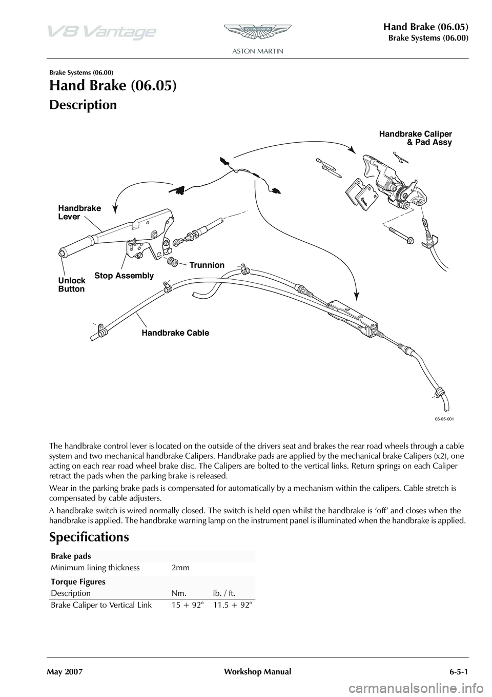
The handbrake control lever is located on the outside of the drivers seat and brakes the rear road wheels through a cable
system and two mechanical handbrake Calipers. Handbrake pads are applied by the mechanical brake Calipers (x2), one
acting on each rear road wheel brake disc. The Calipers are bo lted to the vertical links. Return springs on each Caliper
retract the pads when the parking brake is released.
Wear in the parking brake pads is compensated for automati cally by a mechanism within the calipers. Cable stretch is
compensated by cable adjusters.
A handbrake switch is wired normally closed. The switch is he ld open whilst the handbrake is ‘off’ and closes when the
handbrake is applied. The handbrake warning lamp on the instrument panel is illuminated when the handbrake is applied.
Specifications
06-05-001
Unlock
Button
Handbrake
Lever
Trunnion
Handbrake Cable
Stop Assembly
Handbrake Caliper
& Pad Assy
Brake pads
Minimum lining thickness 2mm
Torque Figures
DescriptionNm.lb. / ft.
Brake Caliper to Vertical Link 15 + 92° 11.5 + 92°
Page 484 of 947
Hand Brake (06.05)
Brake Systems (06.00)6-5-2 Workshop Manual May 2007
Maintenance
RH/LH Handbrake Caliper-Renew
Removal
1. Raise vehicle on ramp.
2. Remove road wheel/s.
3. Ensure handbrake leve r is fully released.
4. Release handbrake adjustment (both sides).
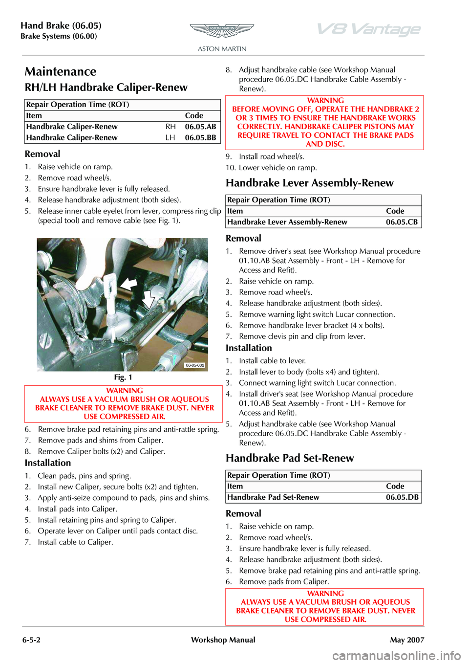
5. Release inner cable eyelet from lever, compress ring clip (special tool) and remove cable (see Fig. 1).
6. Remove brake pad retaining pins and anti-rattle spring.
7. Remove pads and shims from Caliper.
8. Remove Caliper bolts (x2) and Caliper.
Installation
1. Clean pads, pins and spring .
2. Install new Caliper, secu re bolts (x2) and tighten.
3. Apply anti-seize compound to pads, pins and shims.
4. Install pads into Caliper.
5. Install retaining pins and spring to Caliper.
6. Operate lever on Caliper until pads contact disc.
7. Install cable to Caliper. 8. Adjust handbrake cable (see Workshop Manual
procedure 06.05.DC Handbrake Cable Assembly -
Renew).
9. Install road wheel/s.
10. Lower vehicle on ramp.
Handbrake Lever Assembly-Renew
Removal
1. Remove driver's seat (see Workshop Manual procedure 01.10.AB Seat Assembly - Front - LH - Remove for
Access and Refit).
2. Raise vehicle on ramp.
3. Remove road wheel/s.
4. Release handbrake adjustment (both sides).
5. Remove warning light switch Lucar connection.
6. Remove handbrake lever bracket (4 x bolts).
7. Remove clevis pin and clip from lever.
Installation
1. Install cable to lever.
2. Install lever to body (bolts x4) and tighten).
3. Connect warning light switch Lucar connection.
4. Install driver's seat (see Workshop Manual procedure 01.10.AB Seat Assembly - Front - LH - Remove for
Access and Refit).
5. Adjust handbrake cable (see Workshop Manual procedure 06.05.DC Handbrake Cable Assembly -
Renew).
Handbrake Pad Set-Renew
Removal
1. Raise vehicle on ramp.
2. Remove road wheel/s.
3. Ensure handbrake lever is fully released.
4. Release handbrake adjustment (both sides).
5. Remove brake pad retaining pins and anti-rattle spring.
6. Remove pads from Caliper.
Repair Operation Time (ROT)
06-05-002
WAR NI NG
BEFORE MOVING OFF, OPERATE THE HANDBRAKE 2
OR 3 TIMES TO ENSURE THE HANDBRAKE WORKS CORRECTLY. HANDBRAKE CALIPER PISTONS MAY REQUIRE TRAVEL TO CONTACT THE BRAKE PADS
AND DISC.
Repair Operation Time (ROT)
ItemCode
Handbrake Lever Assembly-Renew 06.05.CB
Repair Operation Time (ROT)
ItemCode
Handbrake Pad Set-Renew 06.05.DB
WAR NI NG
ALWAYS USE A VACUUM BRUSH OR AQUEOUS
BRAKE CLEANER TO REMOVE BRAKE DUST. NEVER USE COMPRESSED AIR.
Page 485 of 947
Hand Brake (06.05)
Brake Systems (06.00)
May 2007 Workshop Manual 6-5-3
7. Remove Calipers bolts (x 4) and move Caliper aside.
Installation
1. Clean pins, springs, Caliper slide pins and pistons.
2. Retract pistons into Calipers.
3. Install Calipers and bolts (x2) to knuckles and tighten.
4. Apply anti-seize compound to pads, pins, and slide pins.
5. Install pads into Caliper.
6. Install retaining pins and springs to Caliper.
7. Operate lever on Caliper until pads contact discs.
8. Adjust handbrake cable (see Workshop Manual
procedure 06.05.DC Handbrake Cable Assembly -
Renew).
9. Install road wheel/s.
10. Lower vehicle on ramp.
Handbrake Cable Assembly-Adjust
1. Ensure handbrake is fully released.
2. Raise vehicle on ramp.
3. Check condition of handbrake cable.
4. Release handbrake cable adjustment (both sides).
5. Adjust cable equally at each Caliper to achieve 4 clicks at lever.
6. Check handbrake is not binding.
7. Lower vehicle on ramp.
8. Ensure warning light is off when handbrake lever is released.
9. Ensure for correct operation of handbrake.
Handbrake Cable Assembly-Vehicle Set-
Renew
Removal
1. Remove driver's seat (see Workshop Manual procedure
01.10.AB Seat Assembly - Front - LH - Remove for
Access and Refit).
2. Raise vehicle on ramp. 3. Remove road wheel/s.
4. Remove exhaust rear sile
ncer box (see Workshop
Manual procedure 09.00.KB Silencer and Bypass Valve
Assembly - Renew).
5. Remove rear heat shield bolts (x4) and clips (x2).
6. Release cable adjustments (both sides).
7. Remove handbrake bracket to access clevis pin and clip and disconnect from lever (see Workshop Manual
procedure 06.05.CB Handbrake Lever Assembly -
Renew).
8. Unclip cable in the cabin.
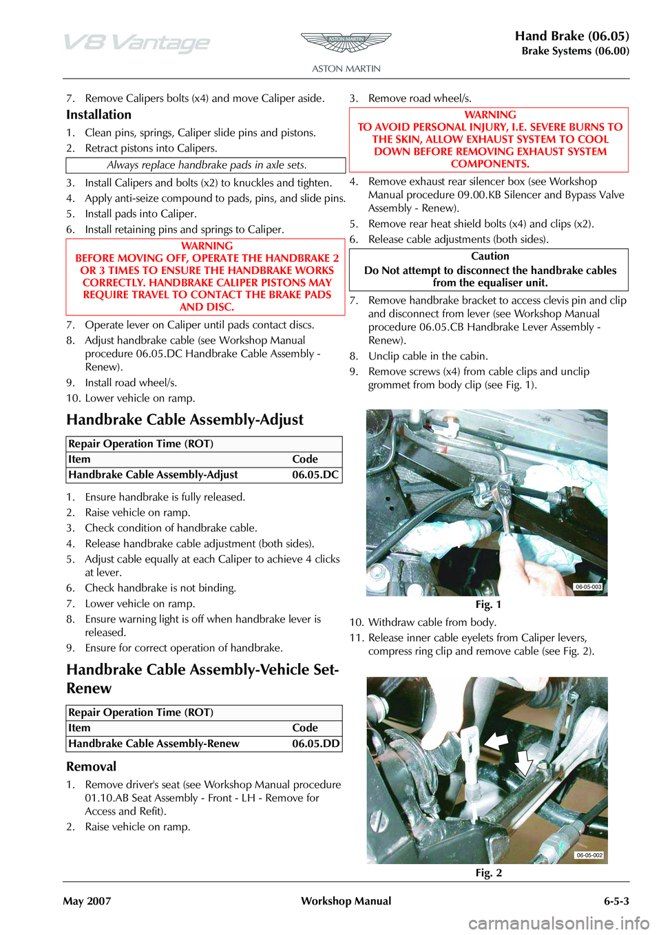
9. Remove screws (x4) from cable clips and unclip grommet from body clip (see Fig. 1).
10. Withdraw cable from body.
11. Release inner cable eyelets from Caliper levers, compress ring clip and remove cable (see Fig. 2).
Always replace handbrake pads in axle sets.
WA R N I N G
BEFORE MOVING OFF, OPERATE THE HANDBRAKE 2 OR 3 TIMES TO ENSURE THE HANDBRAKE WORKS
CORRECTLY. HANDBRAKE CALIPER PISTONS MAY REQUIRE TRAVEL TO CONTACT THE BRAKE PADS AND DISC.
Repair Operation Time (ROT)
Repair Operation Time (ROT)
WA R N I N G
TO AVOID PERSONAL INJURY, I.E. SEVERE BURNS TO
THE SKIN, ALLOW EXHAUST SYSTEM TO COOL DOWN BEFORE REMOVING EXHAUST SYSTEM COMPONENTS.
Caution
Do Not attempt to disconne ct the handbrake cables
from the equaliser unit.
Fig. 1
Fig. 2
06-05-003
06-05-002
Page 486 of 947

Hand Brake (06.05)
Brake Systems (06.00)6-5-4 Workshop Manual May 2007
12. Remove cable from subframe.
Installation
1. Install cable into body.
2. Connect cable to handbrake lever and install handbrake lever (see Workshop Manual procedure 06.05.CB
Handbrake Lever Assembly - Renew).
3. Clip cable in cabin
4. Install cable to subframe (bolts x4).
5. Install heat shield bolts (x4) and clips (x2).
6. Install exhaust rear silencer box (see Workshop Manual procedure 09.00.KB Silencer and Bypass Valve
Assembly - Renew).
7. Install cable to Calipers.
8. Install driver's seat (see Workshop Manual procedure 01.10.AB Seat Assembly - Front - LH - Remove for
Access and Refit).
9. Adjust handbrake cable (see Workshop Manual procedure 06.05.DC Handbrake Cable Assembly -
Renew).
10. Install road wheel/s.
11. Lower vehicle on ramp. Ensure that the handbrake
lever is fully released.
WAR NI NG
BEFORE MOVING OFF, OPERATE THE HANDBRAKE 2
OR 3 TIMES TO ENSURE THE HANDBRAKE WORKS CORRECTLY. HANDBRAKE CALIPER PISTONS MAY
REQUIRE TRAVEL TO CONTACT THE BRAKE PADS AND DISC.
If the handbrake pads are bind ing, a squeal will be emitted
from the rear brakes.
Page 507 of 947
Anti-lock Braking System (ABS) (06.09)
Brake system (06.00)
Issue 4, November 2008 Workshop Manual 6-9-1
Brake system (06.00)
Anti-lock Braking System (ABS) (06.09)
The anti-lock braking system (ABS) is a four-channel system
having independent inputs from all four-wheel speed
sensors.
The ABS module, monitors signals from the sensors to
calculate, brake slip and the acceleration / deceleration of
individual wheels. When the brake pedal is depressed, and
the ABS module detects incipient wheel lock-up from the
incoming signals, it triggers the re-circulation pump inside
the module’s hydraulic modulator, and the solenoid valves
for the wheel(s) concerned. Brake pressure, is then
modulated to increase / decrease or remain constant at the
wheel(s) concerned until whee l lock-up is eliminated. The
ABS provides self-diagnosis and any malfunction within the
system will be indicated to the dr iver by the illumination of
the brake warning light and ‘ABS FAULT’ displayed in the
message centre right. Should a fault develop within the ABS,
the brake system will operate conventionally and with the
same standard of performanc e as a vehicle not equipped
with ABS.
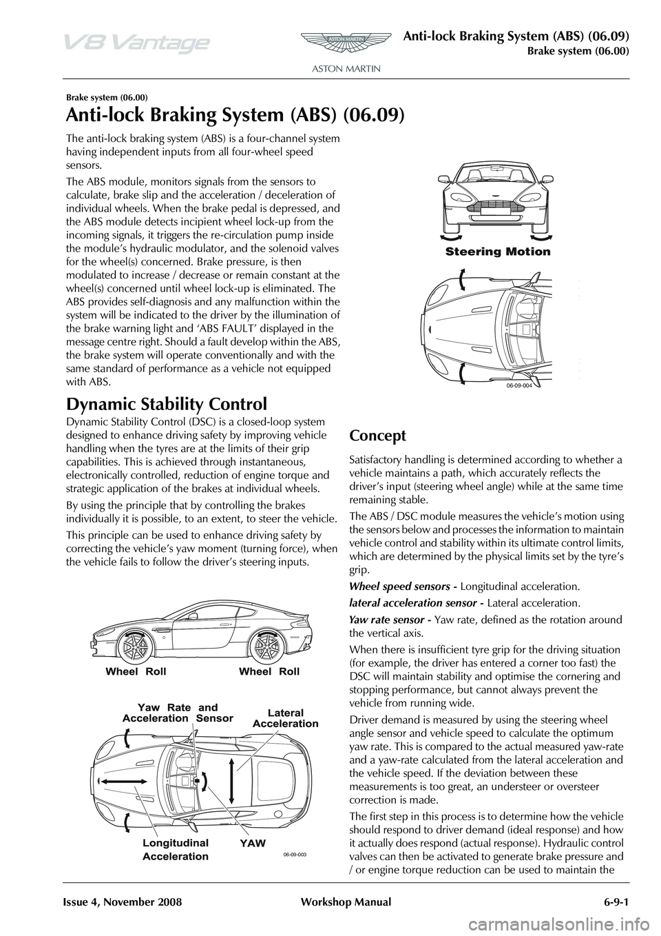
Dynamic Stability Control
Dynamic Stability Control (DSC ) is a closed-loop system
designed to enhance driving safety by improving vehicle
handling when the tyres are at the limits of their grip
capabilities. This is achieved through instantaneous,
electronically controlled, reduction of engine torque and
strategic application of the brakes at individual wheels.
By using the principle that by controlling the brakes
individually it is possible, to an extent, to steer the vehicle.
This principle can be used to enhance driving safety by
correcting the vehicle’s yaw moment (turning force), when
the vehicle fails to follow th e driver’s steering inputs.
Concept
Satisfactory handling is determined according to whether a
vehicle maintains a path, wh ich accurately reflects the
driver