hand brake ASTON MARTIN V8 VANTAGE 2010 User Guide
[x] Cancel search | Manufacturer: ASTON MARTIN, Model Year: 2010, Model line: V8 VANTAGE, Model: ASTON MARTIN V8 VANTAGE 2010Pages: 947, PDF Size: 43.21 MB
Page 435 of 947

Rear Suspension (04.02)
Suspension (04.00)
May 2007 Workshop Manual 4-2-1
Suspension (04.00)
Rear Suspension (04.02)
Description
Anti-roll Bar
An anti-roll bar, mounted on the rear subframe connects to
the LH and RH lower suspension arms via drop links. The
drop links, with a ball joint at either end, transmit vertical
movement of the rear suspension to the anti-roll bar,
minimising body roll.
Vertical Link
The vertical link carries the hub, the cartridge wheel bearing,
the ABS rotor, the wheel speed sensor, the brake caliper, the
hand brake caliper and the brake disc and shield.
A toe control (track-rod) arm secures the rear of the vertical
link to the subframe. The toe control arm is adjustable, on
an eccentric cam, to alter the rear road wheel toe alignment.
04-02-001
Upper Wishbone
Rear Hub Assy
Rear Subframe Lower WishboneAnti Roll Bar LinkAnti Roll Bar
Track Control Arm
Track Control Arm
Page 436 of 947
Rear Suspension (04.02)
Suspension (04.00)4-2-2 Workshop Manual May 2007
Specifications
Maintenance
RH/LH Rear Hub and Bearing Assembly-
Renew
Removal
1. Raise vehicle on ramp.
2. Remove road wheel(s).
3. Remove RH/LH rear drivesha ft (see Workshop Manual
procedure 05.05.BB/05.05.AB Drive Shaft Assembly -
RH/LH - Renew).
4. Ease caliper pistons to release pads.
5. Remove caliper Allen bolts (x2) release caliper and tie aside.
6. Remove handbrake caliper bolts (x2) and tie caliper aside. 7. Remove brake disc Torx screws (x2), remove disc.
8. Disconnect multiplug fr
om wheel speed sensor.
9. Remove Torx securing wheel speed sensor to vertical link, remove sensor.
10. Remove Allen bolts (x4) se curing hub bearing assembly
in vertical link.
11. Release/remove hub bearing a ssembly from vertical link.
Installation
1. Clean vertical link and mating face on hub bearing
carrier.
2. Install hub bearing assembly. Install and torque tighten Allen bolts (x4).
3. Clean wheel speed sensor.
4. Install wheel speed sensor, install and torque tighten Torx screw.
5. Connect multiplug to wheel sped sensor.
6. Clean disc.
7. Install disc, install and torq ue tighten Torx screws (x2).
8. Install caliper, install and torque tighten Allen bolts (x2).
9. Install handbrake caliper, install and torque tighten
retaining bolts (x2).
10. Install RH/LH driveshaft (see Workshop Manual
procedure 05.05.BB/05.05.AB Drive Shaft Assembly -
RH/LH - Renew).
11. Pump brake pedal.
12. Install road wheel(s).
13. Lower vehicle on ramp.
RH/LH Rear Lower Arm Assembly-Renew
Removal
1. Raise vehicle on ramp.
2. Remove road wheel(s).
3. Remove nut, anti-roll bar li nk to lower suspension arm.
Release link.
4. Remove bolt securing damper to lower suspension arm.
5. Remove bolt and nut/bolt, securing lower suspension arm to subframe.
6. Remove nut/bolt securing lower suspension arm to
vertical link.
7. Release/remove lower suspension arm from subframe and vertical link.
Installation
1. Clean lower suspension arm and mating faces on vertical link, subframe, damper and anti-roll bar link.
2. Install lower suspension ar m to subframe and vertical
link.
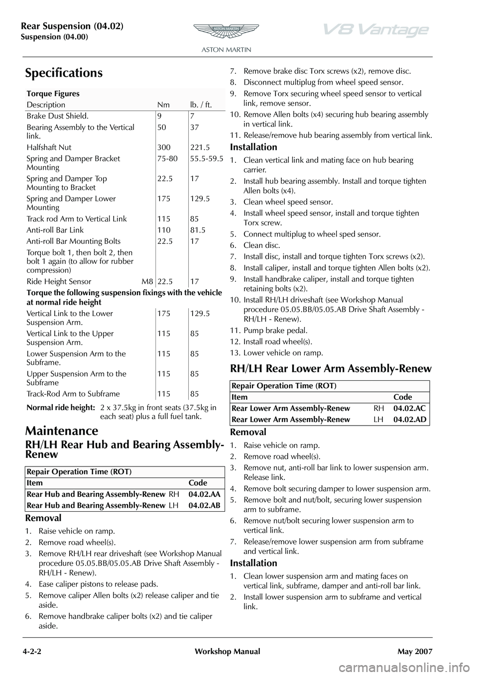
Torque Figures
DescriptionNmlb. / ft.
Brake Dust Shield. 9 7
Bearing Assembly to the Vertical
link. 50 37
Halfshaft Nut 300 221.5
Spring and Damper Bracket
Mounting 75-80 55.5-59.5
Spring and Damper Top
Mounting to Bracket 22.5 17
Spring and Damper Lower
Mounting 175 129.5
Track rod Arm to Vertical Link 115 85
Anti-roll Bar Link 110 81.5
Anti-roll Bar Mounting Bolts
Torque bolt 1, then bolt 2, then
bolt 1 again (to allow for rubber
compression) 22.5 17
Ride Height Sensor M8 22.5 17
Torque the following suspensi on fixings with the vehicle
at normal ride height
Vertical Link to the Lower
Suspension Arm. 175 129.5
Vertical Link to the Upper
Suspension Arm. 115 85
Lower Suspension Arm to the
Subframe. 115 85
Upper Suspension Arm to the
Subframe 115 85
Track-Rod Arm to Subframe 115 85
Normal ride height: 2 x 37.5kg in front seats (37.5kg in
each seat) plus a full fuel tank.
Repair Operation Time (ROT)
Repair Operation Time (ROT)
ItemCode
Rear Lower Arm Assembly-Renew RH04.02.AC
Rear Lower Arm Assembly-Renew LH04.02.AD
Page 438 of 947

Rear Suspension (04.02)
Suspension (04.00)4-2-4 Workshop Manual May 2007
Installation
1. Clean anti-roll bar, bushes, bush straps and links.
2. Install links (x2), to anti-roll bar. Install washers (x2) and nuts (x2). Do not torque tighten.
3. Install bushes (x2) on anti-roll bar.
4. Position anti-roll bar, align bushes (x2), install straps (x2), install bolts (x4). Do not torque tighten.
5. Position anti-roll bar drop links to lower arms, install
nuts (x2). Do not torque tighten.
6. Install rear undertray (see Workshop Manual procedure 01.02.PB Undertray - Rear - Renew).
7. Lower vehicle on ramp.
8. Torque tighten link nuts (x4).
9. Torque tighten bush strap bolts (x4).
Rear Pair-Anti-Roll Bar Bushing-Renew
Removal
1. Raise vehicle on ramp.
2. Remove rear undertray(see Workshop Manual procedure01.02.PB Undertray - Rear - Renew).
3. Remove bolts (x4) securing anti-roll bar bush straps (x2) to subframe.
4. Release/remove bush straps.
5. Remove bushes (x2) from anti-roll bar.
Installation
1. Clean anti-roll bar and bush straps.
2. Install bushes onto anti-roll bar.
3. Install bush straps (x2), install bolts (x4). Do not torque tighten at this stage.
4. Install rear undertray(see Workshop Manual procedure 01.02.PB Undertray - Rear - Renew).
5. Lower vehicle on ramp.
6. Torque tighten all suspension nuts/bolts.
RH/LH Rear Anti-Roll Bar Link-Renew
Removal
1. Raise vehicle on ramp.
1. Remove nut, collect wash er, link to anti-roll bar.
1. Remove nut, link to lower suspension arm. Remove link.
Installation
1. Clean link and mating faces on anti-roll bar and lower suspension arm.
2. Install link to anti-roll bar, install washer and nut. Do not
torque tighten at this stage.
3. Position link to lower suspension arm, install nut). Do not torque tighten at this stage.
4. Lower vehicle on ramp.
5. Torque tighten link nuts (x2).
RH/LH Rear Hub Vertical Link-Renew
Removal
1. Raise vehicle on ramp.
2. Remove road wheel/s
3. With assistance, remove rear hub nut.
4. Remove nut/bolt, securing toe rod to vertical link, release toe rod.
5. Disconnect ABS sensor multiplug.
6. Remove Torx screw securing ABS sensor, remove sensor
7. Ease caliper pistons to release pads.
8. Remove caliper Allen bolts (x2) release caliper and tie aside.
9. Remove handbrake caliper bolts (x2) and tie caliper aside.
10. Remove brake disc Torx screws (x2) remove disc.
11. Remove nut/bolt securing lower suspension arm to
vertical link.
12. Remove nut/bolt securing vertical link to upper
suspension arm.
13. Release vertical link from driveshaft, remove vertical
link.
Caution
Final tightening of suspen sion components must be
carried out with the suspension arms at normal ride
height. Failure to do this will over stress the suspension bushes when the suspension is deflected to maximum
upward travel.
Repair Operation Time (ROT)
Repair Operation Time (ROT)
ItemCode
Rear Anti-Roll Bar Link-Renew RH04.02.BD
Rear Anti-Roll Bar Link-Renew LH04.02.BE
Caution
Final tightening of suspen sion components must be
carried out with the suspension arms at normal ride
height. Failure to do this wi ll over stress the suspension
bushes when the suspension is deflected to maximum
upward travel.
Repair Operation Time (ROT)
ItemCode
Rear Hub Vertic al Link-Renew RH04.02.HB
Rear Hub Vertic al Link-Renew LH04.02.GB
Page 439 of 947

Rear Suspension (04.02)
Suspension (04.00)
May 2007 Workshop Manual 4-2-5
14. Tie driveshaft aside.
15. Remove Allen bolts (x4) securing hub bearing assembly in vertical link.
16. Release/remove hub bearing assembly from vertical link.
17. Remove Torx screws (x4) secu ring disc shield to vertical
link.
Installation
1. Clean vertical link, disc sh ield and hub bearing carrier.
2. Install disc shield to vert ical link, install and torque
tighten Torx screws (x4).
3. Install hub bearing assembly in vertical link. Install and tighten Allen bolts.
4. Release driveshaft.
5. Align to driveshaft, install vertical link to upper suspension arm. Install bolt/nut. Do not torque tighten at
this stage.
6. Align vertical link to lower suspension arm. Install bolt/ nut. Do not torque tighten at this stage.
7. Install hub nut. Do not torque tighten at this stage.
8. Clean brake disc.
9. Install disc and Torx screws (x2) and tighten Torx screws.
10. Install caliper and Allen bolts (x2) and tighten to.
11. Install handbrake caliper and retaining bolts (x2), tighten bolts.
12. Install ABS speed sensor, install and torque tighten Torx screw.
13. Install ABS sensor multiplug.
14. Install toe rod to vertical link, install bolt/nut. Do not torque tighten at this stage.
15. Install road wheel/s
16. Pump brake pedal.
17. Lower vehicle on ramp.
18. With assistance, torque tighten rear hub nut.
19. Correctly torque tighten all suspension nuts/bolts.
20. 4 wheel alignment - check/ adjust(see Workshop Manual
procedure 04.00.AD 4 Wheel Alignment - Check and
Adjust)
Repair Operation Time (ROT)
Page 446 of 947

Shock Absorber System (04.03)
Suspension (04.00)4-3-6 Workshop Manual May 2007
9. Release sensor harness clips (x2) from toe control arm (see Fig. 3).
10. Remove bolts (x2) each side from handbrake calliper to rear hub and release calliper an d position aside (see Fig.
4)
.
11. Remove nuts and bolts both sides from toe control arms (see Fig. 5). 12. Remove nuts and bolts each side from lower damper
mountings (see Fig. 6).
13. Remove bolts (x4) each side from damper upper mounting (see Fig. 7).
Fig. 3
Fig. 4
Fig. 5
Fig. 6
Fig. 7
Page 447 of 947
Shock Absorber System (04.03)
Suspension (04.00)
May 2007 Workshop Manual 4-3-7
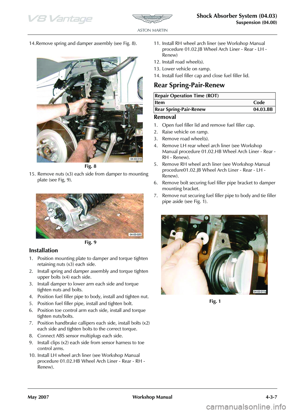
14. Remove spring and damper assembly (see Fig. 8).
15. Remove nuts (x3) each side from damper to mounting plate (see Fig, 9).
Installation
1. Position mounting plate to damper and torque tighten retaining nuts (x3) each side.
2. Install spring and damper assembly and torque tighten upper bolts (x4) each side.
3. Install damper to lower arm each side and torque tighten nuts and bolts.
4. Position fuel filler pipe to body, install and tighten nut.
5. Position fuel filler pipe, install and tighten bolt.
6. Position toe control arm each side, install and torque tighten nuts/bolts.
7. Position handbrake callipers each side, install bolts (x2) each side and tighten bolts to the correct torque.
8. Connect ABS sensor multiplugs each side.
9. Install clips (x2) each side from sensor harness to toe control arms.
10. Install LH wheel arch liner (see Workshop Manual procedure 01.02.HB Wheel Arch Liner - Rear - RH -
Renew). 11. Install RH wheel arch li
ner (see Workshop Manual
procedure 01.02.JB Wheel Arch Liner - Rear - LH -
Renew)
12. Install road wheel(s).
13. Lower vehicle on ramp.
14. Install fuel filler cap and close fuel filler lid.
Rear Spring-Pair-Renew
Removal
1. Open fuel filler lid and remove fuel filler cap.
2. Raise vehicle on ramp.
3. Remove road wheel(s).
4. Remove LH rear wheel arch liner (see Workshop Manual procedure 01.02.HB Wheel Arch Liner - Rear -
RH - Renew).
5. Remove RH wheel arch liner (see Workshop Manual procedure01.02.JB Wheel Arch Liner - Rear - LH -
Renew).
6. Remove bolt securing fuel filler pipe bracket to damper
mounting bracket.
7. Remove nut securing fuel fille r pipe to body and tie filler
pipe aside (see Fig. 1).
Fig. 8
Fig. 9
Repair Operation Time (ROT)
Page 448 of 947

Shock Absorber System (04.03)
Suspension (04.00)4-3-8 Workshop Manual May 2007
8. Disconnect ABS sensor multiplug (see Fig. 2).
9. Release sensor harness clips (x2) from toe control arm (see Fig. 3).
10. Remove bolts (x2) each side from handbrake calliper to rear hub and release calliper an d position aside (see Fig.
4)
.
11. Remove nuts and bolts both sides from toe control arms (see Fig. 5).
12. Remove nuts and bolts each side from lower damper mountings (see Fig. 6).
Fig. 2
Fig. 3
Fig. 4
Fig. 5
Fig. 6
Page 449 of 947
Shock Absorber System (04.03)
Suspension (04.00)
May 2007 Workshop Manual 4-3-9
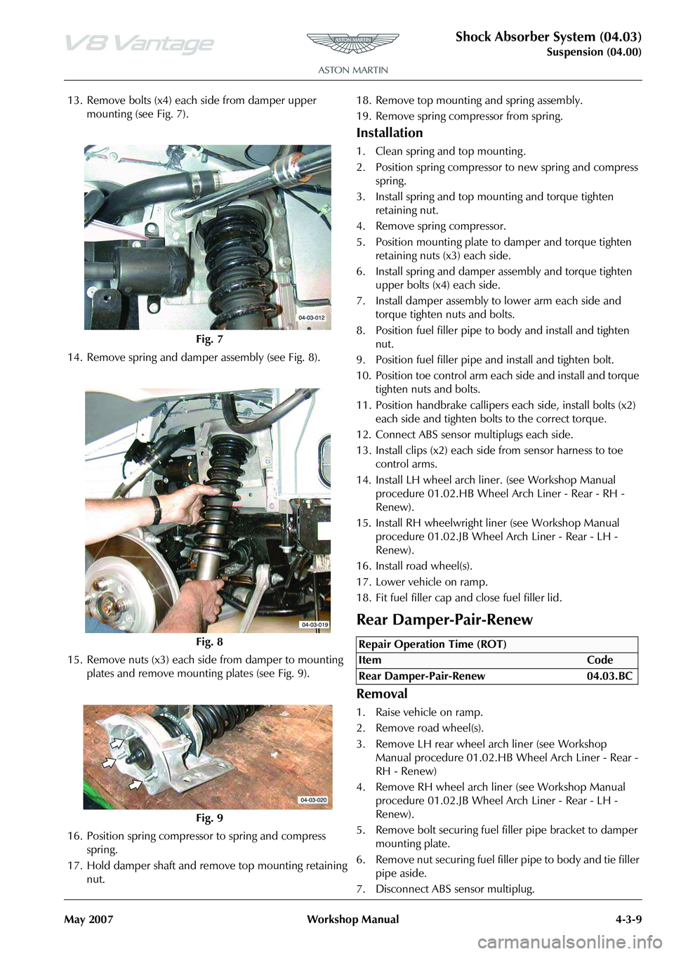
13. Remove bolts (x4) each side from damper upper mounting (see Fig. 7).
14. Remove spring and damper assembly (see Fig. 8).
15. Remove nuts (x3) each side from damper to mounting plates and remove mounting plates (see Fig. 9).
16. Position spring compresso r to spring and compress
spring.
17. Hold damper shaft and remove top mounting retaining nut. 18. Remove top mounting and spring assembly.
19. Remove spring compressor from spring.
Installation
1. Clean spring and top mounting .
2. Position spring compressor to new spring and compress
spring.
3. Install spring and top mounting and torque tighten retaining nut.
4. Remove spring compressor.
5. Position mounting plate to damper and torque tighten
retaining nuts (x3) each side.
6. Install spring and damper assembly and torque tighten upper bolts (x4) each side.
7. Install damper assembly to lower arm each side and torque tighten nuts and bolts.
8. Position fuel filler pipe to body and install and tighten nut.
9. Position fuel filler pipe and install and tighten bolt.
10. Position toe control arm each side and install and torque tighten nuts and bolts.
11. Position handbrake callipers each side, install bolts (x2) each side and tighten bolts to the correct torque.
12. Connect ABS sensor multiplugs each side.
13. Install clips (x2) each side from sensor harness to toe control arms.
14. Install LH wheel arch li ner. (see Workshop Manual
procedure 01.02.HB Wheel Arch Liner - Rear - RH -
Renew).
15. Install RH wheelwright li ner (see Workshop Manual
procedure 01.02.JB Wheel Arch Liner - Rear - LH -
Renew).
16. Install road wheel(s).
17. Lower vehicle on ramp.
18. Fit fuel filler cap and close fuel filler lid.
Rear Damper-Pair-Renew
Removal
1. Raise vehicle on ramp.
2. Remove road wheel(s).
3. Remove LH rear wheel arch liner (see Workshop Manual procedure 01.02.HB Wheel Arch Liner - Rear -
RH - Renew)
4. Remove RH wheel arch liner (see Workshop Manual procedure 01.02.JB Wheel Arch Liner - Rear - LH -
Renew).
5. Remove bolt securing fuel filler pipe bracket to damper
mounting plate.
6. Remove nut securing fuel fille r pipe to body and tie filler
pipe aside.
7. Disconnect ABS sensor multiplug.
Fig. 7
Fig. 8
Fig. 9
Repair Operation Time (ROT)
Page 450 of 947
Shock Absorber System (04.03)
Suspension (04.00)4-3-10 Workshop Manual May 2007
8. Release sensor harness clips (x2) from toe control arm.
9. Remove bolts (x2) each side from handbrake calliper to rear hub.
10. Release calliper and position aside.
11. Remove nuts and bolts both sides from toe control arms.
12. Remove nuts and bolts each side from lower damper mountings.
13. Remove bolts (x4) each side from damper upper mounting.
14. Remove spring and damper assembly.
15. Remove nuts (x3) each side from damper to mounting plates and remove mounting plates.
16. Position spring compressor to spring and compress spring.
17. Hold damper shaft and remove top mounting retaining nut.
18. Remove top mounting and spring assembly.
19. Remove dust shield, rebound bumper and spring seat flange.
Installation
1. Clean spring, spring seat flange, rebound bumper, dust
shield and top mounting .
2. Install spring seat flange, rebound bumper and dust shield onto damper.
3. Install spring and top mounting and fit and tighten retaining nut.
4. Remove spring compressor.
5. Position mounting plate to damper and torque tighten retaining nuts (x3).
6. Install spring and damper assembly and torque tighten upper bolts (x4) each side.
7. Install damper assembly to lower arm each side and torque tighten nuts and bolts.
8. Position fuel filler pipe to body and install and tighten nut.
9. Position fuel filler pipe and install and tighten bolt.
10. Position toe control arm each side and install and torque tighten nuts and bolts.
11. Position handbrake callipers each side, install bolts (x2) each side and tighten bolts to the correct torque.
12. Connect ABS sensor multiplugs each side.
13. Install clips (x2) each side from sensor harness to toe control arms.
14. Install LH wheel arch liner (see Workshop Manual procedure 01.02.HB Wheel Arch Liner - Rear - RH -
Renew).
15. Install RH wheel arch liner (see Workshop Manual procedure 01.02.JB Wheel Arch Liner - Rear - LH -
Renew)
16. Install road wheel(s).
17. Lower vehicle on ramp.
Page 453 of 947
Road Wheels and Tyres (04.04)
Suspension (04.00)
May 2007 Workshop Manual 4-4-3
Maintenance
Factory installed tyres and road wheels are designed to
operate satisfactory when inflated to the recommended
inflation pressures (Refer to ’Inspection and Verification’,
page 4-4-4). The recommended pressures apply to vehicle
loads up to and including the full-rated load capacity.
Correct tyre pressures and driving technique have an
important influence on tyre life. Heavy cornering,
excessively rapid acceleration and unnecessary sharp
braking increase tyre wear.
Replacement tyres should follow the recommended:
The use of any other size or type may seriously affect:
Wheels need to be renewed when:
Safety
Tyre Replacement and Wheel
Interchanging
When replacement of tyres is required it is preferable to
install a complete vehicle set. S hould either the front or rear
tyres only show excessive wear, new tyres must be installed
to replace worn ones. Under no circumstances interchange
tyres from side to side, front to re ar or vice versa as individual
tyre wear produces unique characteristics depending upon
their position. If the position is changed after wear has
occurred, the performance of the tyre will be adversely
affected.
New tyres must be balanced before installing to the vehicle.
•Size
•Speed rating
•Load range
• Radial construction type
•Safety
•Ride
•Handling
• Speedometer and Odometer calibration • Vehicle ground clearance
• Tyre clearance between
body and chassis
• Wheel bearing life
• Brake cooling
• Impact damaged
• Heavily corroded
• Porous • Wheel stud holes or seats
become damaged
• They have excessive radial or lateral runout.
ENSURE THAT TYRES ARE MOUNTED WITH THE
SIDEWALL MARKING ‘OUTSIDE’ SHOWING ON THE
OUTER SIDEWALL FACE.
CORRECT TYRE ROTATIONAL DIRECTION IS CRITICAL.
WA R N I N G
A TYRE AND WHEEL MUST ALWAYS BE CORRECTLY MATCHED. WIDER OR NARROWER TYRES THAN
RECOMMENDED COULD CAUSE DANGER THROUGH
SUDDEN DEFLATION.
WA R N I N G
WHEN CHANGING A WHEEL, MAKE SURE THAT THE VEHICLE CANNOT MOVE. ALWAYS APPLY THE
PARKING BRAKE AND SELE CT THE TRANSMISSION
PARK POSITION (AUTOMATIC TRANSMISSION ONLY).
WA R N I N G
NEVER RUN THE ENGINE WITH ONE WHEEL OFF THE GROUND, FOR EXAMPLE, WHEN CHANGING THE
WHEEL. THE WHEEL RESTING ON THE GROUND MAY CAUSE THE VEHICLE TO MOVE.
WA R N I N G
ALWAYS TIGHTEN THE WHEEL NUTS TO
SPECIFICATION. TOO TIGHT MAY CAUSE DAMAGE,
TOO LOOSE MAY ALLOW TH E WHEEL TO BECOME
DETACHED.
WAR NI NG
DO NOT MIX DIFFERENT TY PES OF TYRES ON THE
SAME VEHICLE. HANDLING MAY BE SERIOUSLY AFFECTED RESULTING IN LOSS OF CONTROL.
WAR NI NG
USE ONLY WHEELS AND WHEEL NUTS SUPPLIED BY
ASTON MARTIN. AFTER MARKET WHEELS OR WHEEL
NUTS MAY NOT INSTALL OR FUNCTION CORRECTLY
AND COULD CAUSE INJURY OR DAMAGE.
Caution
When a new tyre is installe d, always renew the tyre
valve.