wheel torque ASTON MARTIN V8 VANTAGE 2010 Service Manual
[x] Cancel search | Manufacturer: ASTON MARTIN, Model Year: 2010, Model line: V8 VANTAGE, Model: ASTON MARTIN V8 VANTAGE 2010Pages: 947, PDF Size: 43.21 MB
Page 447 of 947
Shock Absorber System (04.03)
Suspension (04.00)
May 2007 Workshop Manual 4-3-7
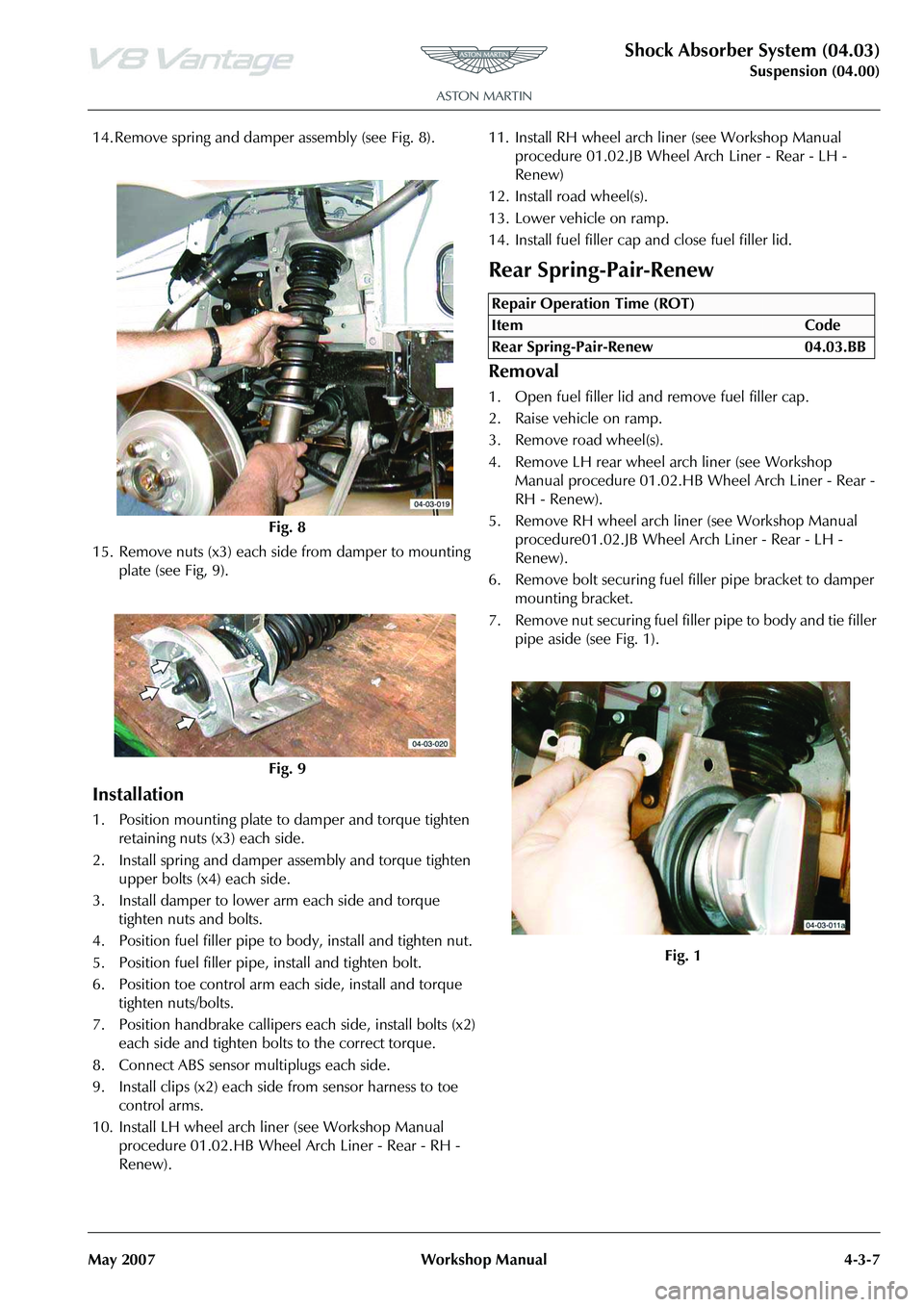
14. Remove spring and damper assembly (see Fig. 8).
15. Remove nuts (x3) each side from damper to mounting plate (see Fig, 9).
Installation
1. Position mounting plate to damper and torque tighten retaining nuts (x3) each side.
2. Install spring and damper assembly and torque tighten upper bolts (x4) each side.
3. Install damper to lower arm each side and torque tighten nuts and bolts.
4. Position fuel filler pipe to body, install and tighten nut.
5. Position fuel filler pipe, install and tighten bolt.
6. Position toe control arm each side, install and torque tighten nuts/bolts.
7. Position handbrake callipers each side, install bolts (x2) each side and tighten bolts to the correct torque.
8. Connect ABS sensor multiplugs each side.
9. Install clips (x2) each side from sensor harness to toe control arms.
10. Install LH wheel arch liner (see Workshop Manual procedure 01.02.HB Wheel Arch Liner - Rear - RH -
Renew). 11. Install RH wheel arch li
ner (see Workshop Manual
procedure 01.02.JB Wheel Arch Liner - Rear - LH -
Renew)
12. Install road wheel(s).
13. Lower vehicle on ramp.
14. Install fuel filler cap and close fuel filler lid.
Rear Spring-Pair-Renew
Removal
1. Open fuel filler lid and remove fuel filler cap.
2. Raise vehicle on ramp.
3. Remove road wheel(s).
4. Remove LH rear wheel arch liner (see Workshop Manual procedure 01.02.HB Wheel Arch Liner - Rear -
RH - Renew).
5. Remove RH wheel arch liner (see Workshop Manual procedure01.02.JB Wheel Arch Liner - Rear - LH -
Renew).
6. Remove bolt securing fuel filler pipe bracket to damper
mounting bracket.
7. Remove nut securing fuel fille r pipe to body and tie filler
pipe aside (see Fig. 1).
Fig. 8
Fig. 9
Repair Operation Time (ROT)
Page 449 of 947
Shock Absorber System (04.03)
Suspension (04.00)
May 2007 Workshop Manual 4-3-9
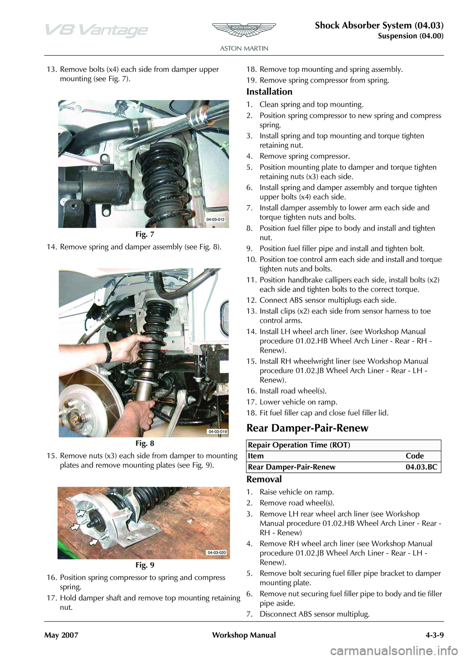
13. Remove bolts (x4) each side from damper upper mounting (see Fig. 7).
14. Remove spring and damper assembly (see Fig. 8).
15. Remove nuts (x3) each side from damper to mounting plates and remove mounting plates (see Fig. 9).
16. Position spring compresso r to spring and compress
spring.
17. Hold damper shaft and remove top mounting retaining nut. 18. Remove top mounting and spring assembly.
19. Remove spring compressor from spring.
Installation
1. Clean spring and top mounting .
2. Position spring compressor to new spring and compress
spring.
3. Install spring and top mounting and torque tighten retaining nut.
4. Remove spring compressor.
5. Position mounting plate to damper and torque tighten
retaining nuts (x3) each side.
6. Install spring and damper assembly and torque tighten upper bolts (x4) each side.
7. Install damper assembly to lower arm each side and torque tighten nuts and bolts.
8. Position fuel filler pipe to body and install and tighten nut.
9. Position fuel filler pipe and install and tighten bolt.
10. Position toe control arm each side and install and torque tighten nuts and bolts.
11. Position handbrake callipers each side, install bolts (x2) each side and tighten bolts to the correct torque.
12. Connect ABS sensor multiplugs each side.
13. Install clips (x2) each side from sensor harness to toe control arms.
14. Install LH wheel arch li ner. (see Workshop Manual
procedure 01.02.HB Wheel Arch Liner - Rear - RH -
Renew).
15. Install RH wheelwright li ner (see Workshop Manual
procedure 01.02.JB Wheel Arch Liner - Rear - LH -
Renew).
16. Install road wheel(s).
17. Lower vehicle on ramp.
18. Fit fuel filler cap and close fuel filler lid.
Rear Damper-Pair-Renew
Removal
1. Raise vehicle on ramp.
2. Remove road wheel(s).
3. Remove LH rear wheel arch liner (see Workshop Manual procedure 01.02.HB Wheel Arch Liner - Rear -
RH - Renew)
4. Remove RH wheel arch liner (see Workshop Manual procedure 01.02.JB Wheel Arch Liner - Rear - LH -
Renew).
5. Remove bolt securing fuel filler pipe bracket to damper
mounting plate.
6. Remove nut securing fuel fille r pipe to body and tie filler
pipe aside.
7. Disconnect ABS sensor multiplug.
Fig. 7
Fig. 8
Fig. 9
Repair Operation Time (ROT)
Page 450 of 947
Shock Absorber System (04.03)
Suspension (04.00)4-3-10 Workshop Manual May 2007
8. Release sensor harness clips (x2) from toe control arm.
9. Remove bolts (x2) each side from handbrake calliper to rear hub.
10. Release calliper and position aside.
11. Remove nuts and bolts both sides from toe control arms.
12. Remove nuts and bolts each side from lower damper mountings.
13. Remove bolts (x4) each side from damper upper mounting.
14. Remove spring and damper assembly.
15. Remove nuts (x3) each side from damper to mounting plates and remove mounting plates.
16. Position spring compressor to spring and compress spring.
17. Hold damper shaft and remove top mounting retaining nut.
18. Remove top mounting and spring assembly.
19. Remove dust shield, rebound bumper and spring seat flange.
Installation
1. Clean spring, spring seat flange, rebound bumper, dust
shield and top mounting .
2. Install spring seat flange, rebound bumper and dust shield onto damper.
3. Install spring and top mounting and fit and tighten retaining nut.
4. Remove spring compressor.
5. Position mounting plate to damper and torque tighten retaining nuts (x3).
6. Install spring and damper assembly and torque tighten upper bolts (x4) each side.
7. Install damper assembly to lower arm each side and torque tighten nuts and bolts.
8. Position fuel filler pipe to body and install and tighten nut.
9. Position fuel filler pipe and install and tighten bolt.
10. Position toe control arm each side and install and torque tighten nuts and bolts.
11. Position handbrake callipers each side, install bolts (x2) each side and tighten bolts to the correct torque.
12. Connect ABS sensor multiplugs each side.
13. Install clips (x2) each side from sensor harness to toe control arms.
14. Install LH wheel arch liner (see Workshop Manual procedure 01.02.HB Wheel Arch Liner - Rear - RH -
Renew).
15. Install RH wheel arch liner (see Workshop Manual procedure 01.02.JB Wheel Arch Liner - Rear - LH -
Renew)
16. Install road wheel(s).
17. Lower vehicle on ramp.
Page 452 of 947
Road Wheels and Tyres (04.04)
Suspension (04.00)4-4-2 Workshop Manual May 2007
USA Tyre Gradings
The following information relates to the tyre grading system
developed by the National Highway Traffic Safety
Administration which grades tyres by tread wear, traction
and temperature performance.
Tr e a d W e a r
Tread wear grade is a comparat ive rating based on the wear
rate of the tyre when tested under controlled conditions
(specified government test course). For example, a tyre
graded 150 would wear one and a half times less on the
government course than a tyre graded 100. Relative
performance of the tyres depends upon actual conditions of
use and may depart significantly from normal due to
variations in driving habits, service practices and differences
in road characteristics and climate.
Tr a c t i o n
Traction grades, A (highest), B and C represent a tyre’s ability
to stop in wet conditions measured on specified government
test surfaces of asphalt and concrete.
Te m p e r a t u r e
Temperature grades, A (highest), B and C, represent a tyre’s
resistance to the generation of wear and its ability to
dissipate heat when tested under controlled conditions
(specified indoor laboratory test road wheel). Sustained high
temperature can cause the material of a tyre to degenerate
and reduce tyre life; excessive temperatures can lead to
sudden tyre failure. Grade ‘C’ corresponds to a level of
performance which all passenger vehicle tyres must meet
under Federal Motor Vehicle Safety Standard No. 109.
Grades ‘B’ and ‘A’ represent higher levels of performance
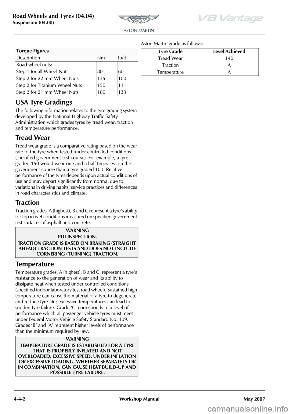
than the minimum required by law. Aston Martin grade as follows:
Torque Figures
DescriptionNmlb/ft
Road wheel nuts:
Step 1 for all Wheel Nuts 80 60
Step 2 for 22 mm Wheel Nuts 135 100
Step 2 for Titanium Wheel Nuts 150 111
Step 2 for 21 mm Wheel Nuts 180 133
WAR NI NG
PDI INSPECTION.
TRACTION GRADE IS BASED ON BRAKING (STRAIGHT AHEAD) TRACTION TESTS AND DOES NOT INCLUDE
CORNERING (TURNING) TRACTION.
WAR NI NG
TEMPERATURE GRADE IS ESTABLISHED FOR A TYRE THAT IS PROPERLY INFLATED AND NOT
OVERLOADED. EXCESSIVE SPEED, UNDER INFLATION
OR EXCESSIVE LOADING, WHETHER SEPARATELY OR
IN COMBINATION, CAN CAUSE HEAT BUILD-UP AND POSSIBLE TYRE FAILURE.
Tyre Grade Level Achieved
Tread Wear 140 Traction A
Temperature A
Page 455 of 947
Road Wheels and Tyres (04.04)
Suspension (04.00)
May 2007 Workshop Manual 4-4-5
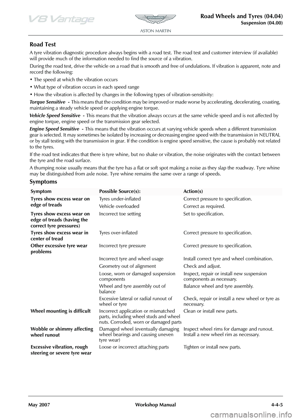
Road Test
A tyre vibration diagnostic proc edure always begins with a road test. The road test and customer interview (if available)
will provide much of the information neede d to find the source of a vibration.
During the road test, drive the vehicle on a road that is smoot h and free of undulations. If vibration is apparent, note and
record the following:
• The speed at which the vibration occurs
• What type of vibration occurs in each speed range
• How the vibration is affected by changes in the following types of vibration-sensitivity:
Torque Sensitive - This means that the condition may be improved or made worse by accelerating, decelerating, coasting,
maintaining a steady vehicle speed or applying engine torque.
Vehicle Speed Sensitive - This means that the vibration always occurs at the same vehicle speed and is not affected by
engine torque, engine speed or the transmission gear selected.
Engine Speed Sensitive - This means that the vibration occurs at varyin g vehicle speeds when a different transmission
gear is selected. It may sometimes be isolated by increasing or decreasing engine speed with the transmission in NEUTRAL
or by stall testing with the transmission in gear. If the condition is engine speed sensitive, the cause is probably not relate d
to the tyres.
If the road test indicates that there is tyre whine, but no sh ake or vibration, the noise originates with the contact between
the tyre and the road surface.
A thumping noise usually means that the tyre has a flat or soft spot making a noise as they slap the roadway. Tyre whine
may be distinguished from axle noise. Tyre whine remains the same over a range of speeds.
Symptoms
SymptomPossible Source(s):Action(s)
Tyres show excess wear on
edge of treads Tyres under-inflated Correct pressure to specification.
Vehicle overloaded Correct as required.
Tyres show excess wear on
edge of treads (having the
correct tyre pressures) Incorrect toe setting Set to specification.
Tyres show excess wear in
center of tread Tyres over-inflated Correct pressure to specification.
Other excessive tyre wear
problems Incorrect tyre pressure Correct pressure to specification.
Incorrect tyre and wheel usage Install correct tyre and wheel combination.
Geometry out of alignm
ent Check and adjust.
Loose, worn or damaged suspension
components Inspect, repair or install new suspension
components as necessary.
Wheel and tyre assembly out of
balance Balance wheel and tyre assembly.
Excessive lateral or radial runout of
wheel or tyre Check, repair or install a new wheel or tyre as
necessary.
Wheel mounting is difficult Incorrect application or mismatched
parts, including wheel studs and wheel
nuts. Corroded, worn or damaged parts Clean or install new parts.
Wobble or shimmy affecting
wheel runout Damaged wheel (eventually damaging
wheel bearings and causing uneven
tyre wear) Inspect wheel rims for damage and runout.
Install a new wheel rim as necessary.
Excessive vibration, rough
steering or severe tyre wear Loose or incorrect attaching parts Tighten or install new parts.
Page 464 of 947
Driveshaft (05.01)
Driveline (05.00)5-1-2 Workshop Manual May 2007
Driveline (05.00)
Driveshaft (05.01)
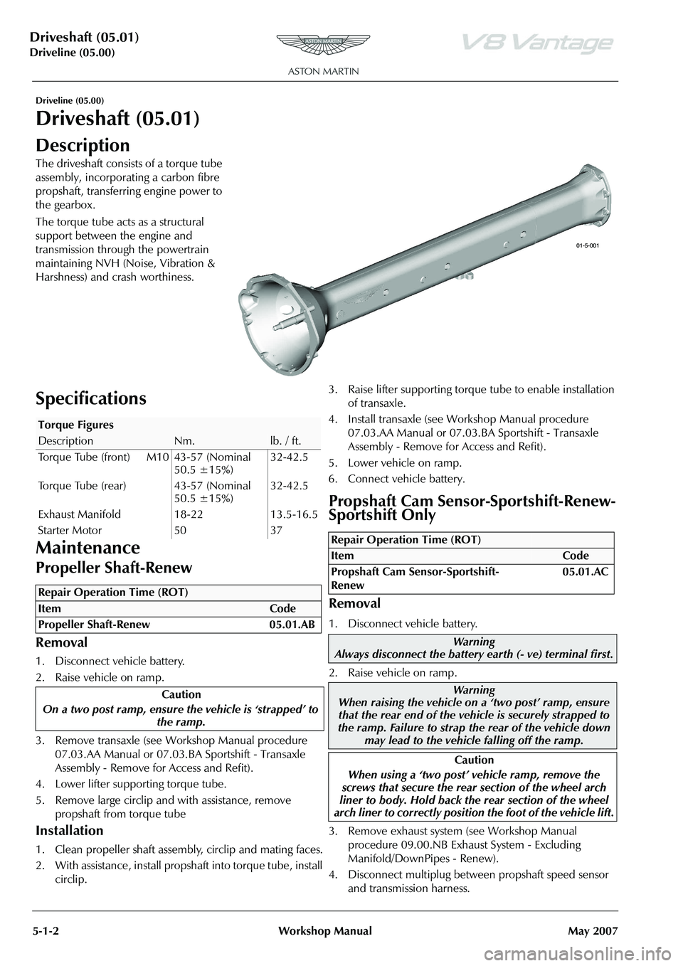
Description
The driveshaft consists of a torque tube
assembly, incorporating a carbon fibre
propshaft, transferring engine power to
the gearbox.
The torque tube acts as a structural
support between the engine and
transmission through the powertrain
maintaining NVH (Noise, Vibration &
Harshness) and crash worthiness.
Specifications
Maintenance
Propeller Shaft-Renew
Removal
1. Disconnect vehicle battery.
2. Raise vehicle on ramp.
3. Remove transaxle (see Workshop Manual procedure 07.03.AA Manual or 07.03.BA Sportshift - Transaxle
Assembly - Remove for Access and Refit).
4. Lower lifter supporting torque tube.
5. Remove large circlip and with assistance, remove propshaft from torque tube
Installation
1. Clean propeller shaft assembly, circlip and mating faces.
2. With assistance, install propshaft into torque tube, install circlip. 3. Raise lifter supporting torque tube to enable installation
of transaxle.
4. Install transaxle (see Workshop Manual procedure 07.03.AA Manual or 07.03.BA Sportshift - Transaxle
Assembly - Remove for Access and Refit).
5. Lower vehicle on ramp.
6. Connect vehicle battery.
Propshaft Cam Sensor-Sportshift-Renew-
Sportshift Only
Removal
1. Disconnect vehicle battery.
2. Raise vehicle on ramp.
3. Remove exhaust system (see Workshop Manual procedure 09.00.NB Exhaust System - Excluding
Manifold/DownPipes - Renew).
4. Disconnect multiplug between propshaft speed sensor and transmission harness.
Torque Figures
DescriptionNm.lb. / ft.
Torque Tube (front) M10 43-57 (Nominal 50.5 ±15%)32-42.5
Torque Tube (rear) 43-57 (Nominal 50.5 ±15%)32-42.5
Exhaust Manifold 18-22 13.5-16.5
Starter Motor 50 37
Repair Operation Time (ROT)
Repair Operation Time (ROT)
ItemCode
Propshaft Cam Sensor-Sportshift-
Renew 05.01.AC
Warning
Always disconnect the battery earth (- ve) terminal first.
Warning
When raising the vehicle on a ‘two post’ ramp, ensure
that the rear end of the vehi cle is securely strapped to
the ramp. Failure to strap th e rear of the vehicle down
may lead to the vehicl e falling off the ramp.
Caution
When using a ‘two post’ vehicle ramp, remove the
screws that secure the rear section of the wheel arch
liner to body. Hold back the rear section of the wheel
arch liner to correctly position the foot of the vehicle lift.
Page 475 of 947
Front Disc Brake (06.03)
Brake Systems (06.00)
Version 6, March 2010 Workshop Manual 6-3-3
Maintenance
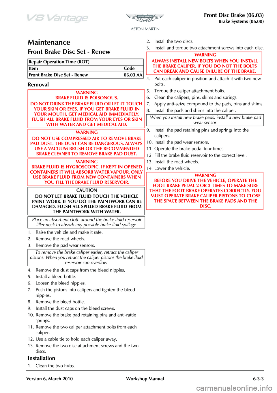
Front Brake Disc Set - Renew
Removal
1. Raise the vehicle and make it safe.
2. Remove the road wheels.
3. Remove the pad wear sensors.
4. Remove the dust caps from the bleed nipples.
5. Install a bleed bottle.
6. Loosen the bleed nipples.
7. Push the pistons into calipers and tighten the bleed nipples.
8. Remove the bleed bottle.
9. Install the dust caps on the bleed screws.
10. Remove the brake pad retaining pins and anti-rattle springs.
11. Remove the two caliper attachment bolts from each caliper.
12. Use a cable tie to hold each caliper away.
13. Remove the two disc attachment screws and the two discs.
Installation
1. Clean the two hubs. 2. Install the two discs.
3. Install and torque two attachment screws into each disc.
4. Put each caliper in position and attach it with two new
bolts.
5. Torque the caliper attachment bolts.
6. Clean the calipers, pins, shims and springs.
7. Apply anti-seize compound to the pads, pins and shims.
8. Install the pads and shims into the caliper.
9. Install the pad retaining pins and springs into the calipers.
10. Install the pad wear sensors.
11. Operate the brake pedal four times.
12. Fill the brake fluid reservoir to the correct level.
13. Install the road wheels.
14. Lower the vehicle.
Repair Operation Time (ROT)
WAR NI NG
ALWAYS INSTALL NEW BOLTS WHEN YOU INSTALL THE BRAKE CALIPER. IF YOU DO NOT THE BOLTS
CAN BREAK AND CAUSE FAILURE OF THE BRAKE.
When you install new brake pads, install a new brake pad wear sensor.
WA R N I N G
BEFORE YOU DRIVE THE VEHICLE, OPERATE THE
FOOT BRAKE PEDAL 2 OR 3 TIMES TO MAKE SURE
THAT THE FOOT BRAKE OPERATES CORRECTLY. YOU MUST OPERATE BRAKE CALIPER PISTONS TO CLOSE THE SPACE BETWEEN THE BRAKE PADS AND THE
DISC.
Page 476 of 947
Front Disc Brake (06.03)
Brake Systems (06.00)6-3-4 Workshop Manual Version 6, March 2010
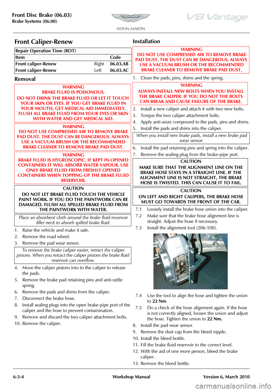
Front Caliper-Renew
Removal
1. Raise the vehicle and make it safe.
2. Remove the road wheel.
3. Remove the pad wear sensor.
4. Move the caliper pistons into to the caliper to release the pads.
5. Remove the brake pad retaining pins and anti-rattle spring.
6. Remove the pads and shims from the caliper.
7. Disconnect the brake hose.
8. Install sealing plugs into the open brake-pipe port of the caliper and the hose to prevent contamination.
9. Remove and discard the two caliper attachment bolts.
10. Remove the caliper.
Installation
1. Clean the pads, pins, shims and the spring .
2. Install a new caliper and attach it with two new bolts.
3. Torque the two caliper attachment bolts.
4. Apply anti-seize compound to the pads, pins and shims.
5. Install the pads and shims into the caliper.
6. Install the pad retaining pins and spring into the caliper.
7. Remove the sealing plug from the brake-pipe port.
7.1 Loosely install the brake hose union into the caliper.
7.2 Make sure that the brake hose alignment line is straight. Adjust the hose if necessary.
7.3 Install the alignment tool (206-100).
7.4 Use the tool to align the hose and tighten the union to 22 Nm .
7.5 Do a check of the hose alignment again. If the hose is not correctly aligned, loosen the union and adjust
the hose. Tighten the union to 22 Nm.
8. Install the pad wear sensor.
9. Remove the dust cap from the bleed nipple.
10. Install the bleed bottle.
11. Fill the brake fluid reservoir to the correct level.
12. With the aid of one more person, bleed the brake caliper.
13. Remove the bleed bottle.
Repair Operation Time (ROT)WAR NI NG
DO NOT USE COMPRESSED AIR TO REMOVE BRAKE
PAD DUST. THE DUST CAN BE DANGEROUS. ALWAYS USE A VACUUM BRUSH OR THE RECOMMENDED BRAKE CLEANER TO REMOVE BRAKE PAD DUST.
WA R N I N G
ALWAYS INSTALL NEW BOLTS WHEN YOU INSTALL THE BRAKE CALIPER. IF YOU DO NOT THE BOLTS
CAN BREAK AND CAUSE FAILURE OF THE BRAKE.
When you install new brake pads, install a new brake pad wear sensor.
CAUTION
MAKE SURE THAT THE ALIGNMENT LINE ON THE BRAKE HOSE STAYS IN A STRAIGHT LINE. IF THE
ALIGNMENT LINE IS NOT STRAIGHT, THE BRAKE HOSE IS TWISTED. THIS CAN CAUSE IT TO FAIL.
CAUTION
ON LEFT AND RIGHT CALIPERS, THE BRAKE HOSE MUST GO TOWARDS THE FRONT OF THE CAR.
Page 477 of 947
Front Disc Brake (06.03)
Brake Systems (06.00)
Version 6, March 2010 Workshop Manual 6-3-5
14. Install the dust cap for the bleed nipple.
15. Fill the brake fluid reservoir to the correct level.
16. Install road wheel.
17. Lower the vehicle.
Front Pad Kit - Renew
Removal
1. Raise the vehicle and make it safe.
2. Remove the road wheels.
3. Remove the pad wear sensors.
4. Remove the dust caps from the bleed nipples .
5. Install a bleed bottle onto each bleed nipple.
6. Loosen the bleed nipples and push pistons into calipers.
7. Tighten bleed nipples.
8. Remove the bleed bottles.
9. Install the dust caps onto the bleed nipples.
10. Remove the brake pad retaining pins and anti-rattle springs.
11. Remove the pads and shims from the calipers.
Installation
1. Clean the calipers, pins, shims and the springs.
2. Apply anti-seize compound to the pads, pins and shims.
3. Install the pads and shims into the caliper.
4. Install the pad retaining pins and springs into the calipers.
5. Install the pad wear sensors.
6. Operate the brake pedal four times.
7. Fill the brake fluid reservoir to the correct level.
8. Install the road wheels.
9. Lower the vehicle.
Front Brake Hose Assembly - Renew
Removal
1. Raise the vehicle and make it safe.
2. Remove the applicable road wheel.
3. Remove the dust cap from the bleed nipple.
4. Install a bleed bottle onto the applicable caliper.
5. Open the bleed nipple.
6. Push the brake pedal approximately 60 mm and hold it with a support.
7. Tighten the bleed nipple.
8. Remove the bleed bottle.
9. Install the dust cap on the bleed nipple.
10. Disconnect the brake hose union from the caliper.
11. Install sealing plugs in the open ports.
12. Remove the brake pipe union from the hose.
13. Remove the M6 screw that attaches the hose bracket to the body.
14. Remove the hose.
Installation
1. Put the hose in position.
2. Install and torque the M6 screw that attaches the hose bracket to the body.
3. Install and torque the brake pipe union onto the hose.
WA R N I N G
BEFORE YOU DRIVE THE VEHICLE, OPERATE THE
FOOT BRAKE PEDAL 2 OR 3 TIMES TO MAKE SURE
THAT THE FOOT BRAKE OPERATES CORRECTLY. YOU MUST OPERATE BRAKE CALIPER PISTONS TO CLOSE
THE SPACE BETWEEN THE BRAKE PADS AND THE DISC.
Repair Operation Time (ROT)
WA R N I N G
DO NOT USE COMPRESSED AIR TO REMOVE BRAKE
PAD DUST. THE DUST CAN BE DANGEROUS. ALWAYS USE A VACUUM BRUSH OR THE RECOMMENDED BRAKE CLEANER TO REMOVE BRAKE PAD DUST.
When you install new brake pads, install a new brake pad wear sensor.
Repair Operation Time (ROT)
Page 481 of 947
Rear Disc Brakes (06.04)
Brake system (06.00)
May 2007 Workshop Manual 6-4-3
Installation
1. Clean components (pads, pins, shims, spring)
2. Install new Caliper and secure bolts (x2) (torque).
3. Apply anti-seize compound to pads, pins and shims.
4. Install pads and shims to Caliper.
5. Install retaining pins and spring to Caliper.
6. Install brake pipe (torque).
7. Install pad wear sensor.
8. Remove bleed nipple dust cap.
9. Fit bleed bottle.
10. Top-up brake fluid.
11. Bleed brake Calipe r with assistance.
12. Install bleed nipple dust caps.
13. Remove bleed bottle.
14. Top-up brake fluid.
15. Install road wheel/s
16. Lower vehicle on ramp.
Rear Pad Kit-Renew
Removal
1. Raise vehicle on ramp.
2. Remove road wheel/s
3. Remove pad wear sensors.
4. Remove bleed nipple dust caps.
5. Fit bleed bottle.
6. Loosen bleed nipples, push pistons into Calipers, tighten bleed nipples.
7. Remove bleed bottle.
8. Fit bleed nipple dust caps
9. Remove brake pad retaining pins and anti-rattle springs.
10. Remove pads and shims from Calipers.
Installation
1. Clean components (Caliper s, pins, shims, springs)
2. Apply anti-seize compound to pads, pins and shims.
3. Install pads and shims to Caliper.
4. Install retaining pad pins and springs to Calipers
5. Install pad wear sensors.
6. Pump brake pedal.
7. Top-up brake fluid.
8. Install road wheel/s
9. Lower vehicle on ramp.
WA R N I N G
ALWAYS USE A VACUUM BRUSH OR AQUEOUS
BRAKE CLEANER TO REMOVE BRAKE DUST. NEVER USE COMPRESSED AIR.
When installing new brake pads, install a new brake pad wear sensor.
When bleeding a brake Calipe r, always bleed the inner
bleed screw first, followed by the outer bleed screw, then
bleed the inner bleed screw once again.
WA R N I N G
BEFORE MOVING OFF, PUMP THE FOOT BRAKE 2 OR 3 TIMES TO ENSURE THE FOOT BRAKE WORKS
CORRECTLY. BRAKE CALIPER PISTONS MAY REQUIRE TRAVEL TO CONTACT THE BRAKE PADS AND DISC.
Repair Operation Time (ROT)
WA R N I N G
AVOID SKIN / EYE CONTACT OR INGESTION OF
BRAKE FLUID. IF SKIN OR EYES ARE SPLASHED WITH BRAKE FLUID, RINSE THE AFFECTED AREA
IMMEDIATELY WITH PLENTY OF WATER AND OBTAIN
MEDICAL ATTENTION. IF BRAKE FLUID IS INGESTED, OBTAIN IMMEDIATE MEDICAL ATTENTION.
WA R N I N G
BRAKE FLUID IS HYGROSCOPI C. IF KEPT IN OPENED
CONTAINERS IT WILL ABSORB WATER VAPOUR. USE ONLY BRAKE FLUID FROM FRESHLY OPENED
CONTAINER.
Caution
Brake fluid must not be allo wed to contact the vehicle
paint work. Remove spilt brake fluid from the paint work by rinsing away with running water.
Place an absorbent cloth arou nd the brake fluid reservoir
filler neck to absorb any po ssible brake fluid spillage.
WA R N I N G
ALWAYS USE A VACUUM BRUSH OR AQUEOUS
BRAKE CLEANER TO REMOVE BRAKE DUST. NEVER USE COMPRESSED AIR.
When installing new brake pa ds, install a new brake pad
wear sensor.
WA R N I N G
BEFORE MOVING OFF, PUMP THE FOOT BRAKE 2 OR 3 TIMES TO ENSURE THE FOOT BRAKE WORKS
CORRECTLY. BRAKE CALIPER PISTONS MAY REQUIRE
TRAVEL TO CONTACT THE BRAKE PADS AND DISC.