ABS ASTON MARTIN V8 VANTAGE 2010 Repair Manual
[x] Cancel search | Manufacturer: ASTON MARTIN, Model Year: 2010, Model line: V8 VANTAGE, Model: ASTON MARTIN V8 VANTAGE 2010Pages: 947, PDF Size: 43.21 MB
Page 654 of 947

Instrument Cluster (13.01)
Information, Gauge and Warning (13.00)
May 2007 Workshop Manual 13-1-3
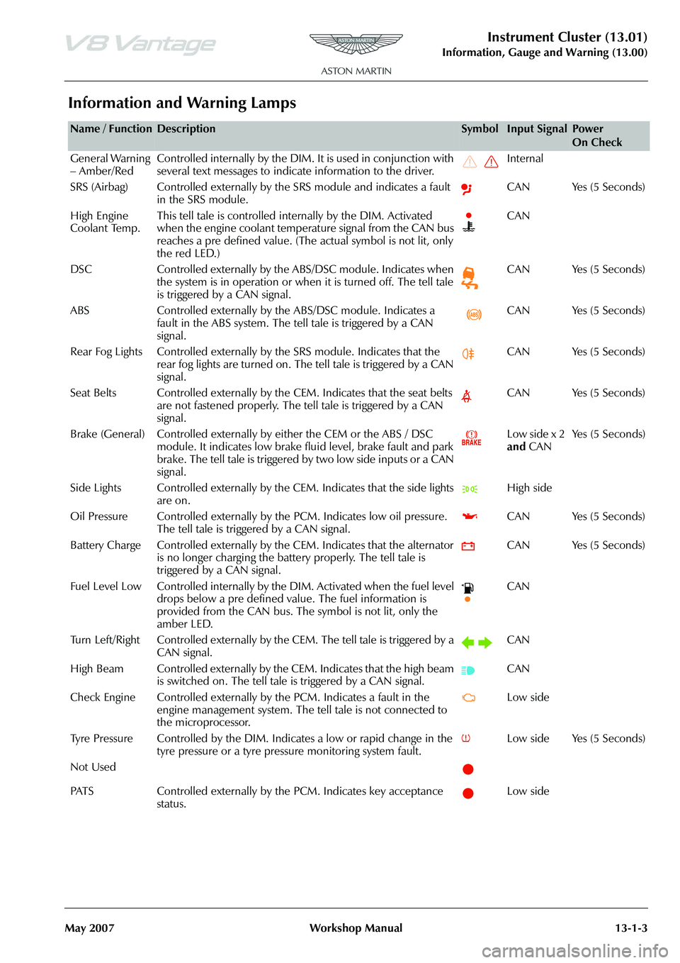
Information and Warning Lamps
Name / FunctionDescriptionSymbolInput SignalPower
On Check
General Warning
– Amber/Red Controlled internally by the DIM. It is used in conjunction with
several text messages to indicate information to the driver. Internal
SRS (Airbag) Controlled externally by the SRS module and indicates a fault in the SRS module. CAN Yes (5 Seconds)
High Engine
Coolant Temp. This tell tale is controlled internally by the DIM. Activated
when the engine coolant temperature signal from the CAN bus
reaches a pre defined value. (The
actual symbol is not lit, only
the red LED.) CAN
DSC Controlled externally by the ABS/DSC module. Indicates when the system is in operation or when it is turned off. The tell tale
is triggered by a CAN signal. CAN Yes (5 Seconds)
ABS Controlled externally by th e ABS/DSC module. Indicates a
fault in the ABS system. The tell tale is triggered by a CAN
signal. CAN Yes (5 Seconds)
Rear Fog Lights Controlled externally by the SRS module. Indicates that the
rear fog lights are turned on. The tell tale is triggered by a CAN
signal. CAN Yes (5 Seconds)
Seat Belts Controlled externally by the CEM. Indicates that the seat belts are not fastened properly. The tell tale is triggered by a CAN
signal. CAN Yes (5 Seconds)
Brake (General) Controlled externally by either the CEM or the ABS / DSC module. It indicates low brake fluid level, brake fault and park
brake. The tell tale is triggered by two low side inputs or a CAN
signal. Low side x 2
and
CAN Ye s ( 5 S e c o n d s )
Side Lights Controlled externally by th e CEM. Indicates that the side lights
are on. High side
Oil Pressure Controlled exte rnally by the PCM. Indicates low oil pressure.
The tell tale is triggered by a CAN signal. CAN Yes (5 Seconds)
Battery Charge Controlled externally by th e CEM. Indicates that the alternator
is no longer charging the battery properly. The tell tale is
triggered by a CAN signal. CAN Yes (5 Seconds)
Fuel Level Low Controlled internally by the DIM. Activated when the fuel level drops below a pre defined value. The fuel information is
provided from the CAN bus. The symbol is not lit, only the
amber LED. CAN
Turn Left/Right Controlled externally by th e CEM. The tell tale is triggered by a
CAN signal. CAN
High Beam Controlled externally by the CEM. Indicates that the high beam is switched on. The tell tale is triggered by a CAN signal. CAN
Check Engine Controlled externally by the PCM. Indicates a fault in the engine management system. The te ll tale is not connected to
the microprocessor. Low side
Tyre Pressure Controlled by the DIM. In dicates a low or rapid change in the
tyre pressure or a tyre pressure monitoring system fault. Low side Yes (5 Seconds)
Not Used
PATS Controlled externally by the PCM. Indicates key acceptance status. Low side
Page 692 of 947

Wiring and Circuit Protection (18.01)
Electric Distribution/Electronic Control (18.00)
May 2007 Workshop Manual 18-1-3
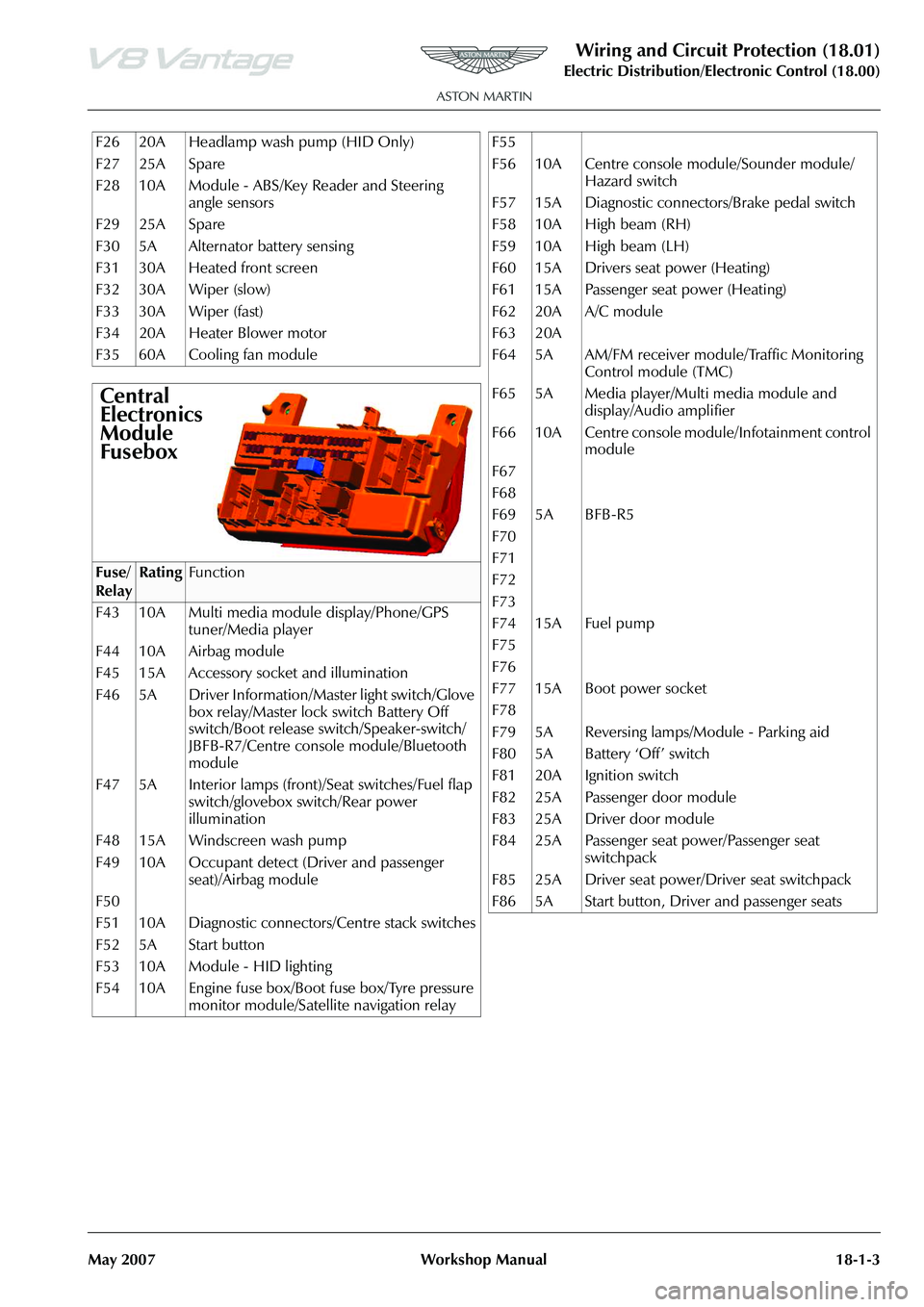
F26 20A Headlamp wash pump (HID Only)
F27 25A Spare
F28 10A Module - ABS/Key Reader and Steering angle sensors
F29 25A Spare
F30 5A Alternator battery sensing
F31 30A Heated front screen
F32 30A Wiper (slow)
F33 30A Wiper (fast)
F34 20A Heater Blower motor
F35 60A Cooling fan module
Central
Electronics
Module
Fusebox
Fuse/
RelayRatingFunction
F43 10A Multi media module display/Phone/GPS tuner/Media player
F44 10A Airbag module
F45 15A Accessory socket and illumination
F46 5A Driver Information/Master light switch/Glove box relay/Master lock switch Battery Off
switch/Boot release switch/Speaker-switch/
JBFB-R7/Centre console module/Bluetooth
module
F47 5A Interior lamps (front)/Seat switches/Fuel flap switch/glovebox switch/Rear power
illumination
F48 15A Windscreen wash pump
F49 10A Occupant detect (Driver and passenger seat)/Airbag module
F50
F51 10A Diagnostic connectors/Centre stack switches
F52 5A Start button
F53 10A Module - HID lighting
F54 10A Engine fuse box/Boot fuse box/Tyre pressure monitor module/Satellite navigation relay
F55
F56 10A Centre console module/Sounder module/
Hazard switch
F57 15A Diagnostic connectors/Brake pedal switch
F58 10A High beam (RH)
F59 10A High beam (LH)
F60 15A Drivers seat power (Heating)
F61 15A Passenger seat power (Heating)
F62 20A A/C module
F63 20A
F64 5A AM/FM receiver module/Traffic Monitoring Control module (TMC)
F65 5A Media player/Multi media module and display/Audio amplifier
F66 10A Centre console module/Infotainment control module
F67
F68
F69 5A BFB-R5
F70
F71
F72
F73
F74 15A Fuel pump
F75
F76
F77 15A Boot power socket
F78
F79 5A Reversing lamps/Module - Parking aid
F80 5A Battery ‘Off’ switch
F81 20A Ignition switch
F82 25A Passenger door module
F83 25A Driver door module
F84 25A Passenger seat power/Passenger seat switchpack
F85 25A Driver seat power/Driver seat switchpack
F86 5A Start button, Driver and passenger seats
Page 694 of 947

Wiring and Circuit Protection (18.01)
Electric Distribution/Electronic Control (18.00)
May 2007 Workshop Manual 18-1-5
The symbol for the screen is an oval with the wires that are
to be screened inside it. The letters ‘SCR’ define the screen.
Controller Area Network (CAN)
Controller Area Network (CAN) is the wiring between
intelligent modules of the vehi cle. This wiring carries the
electronic data around the vehicle allowing the various
modules and components to interrogate the network and
read their specific data signals.
There are 2 different speeds of network.
Low speed - Transmits at 125,000 bits per second. Mainly
for body controller systems such as seats and doors
High speed - Transmits at 500,000 bits per second. Mainly
for engine management and powertrain associated systems
such as ABS.
All wiring in the CAN is twisted. The twisted wires always
consist of one wire with a black trace in it for the negative
side and one with a brown trace in it for the positive.
High Speed CAN wire
Low Speed CAN wire
The symbol below shows a module or a component
connector with the pin numbers that have CAN wires
coming from them.
‘CAN LS+’ - Low speed CAN positive side
‘CAN LS-’ - Low speed CAN Negative Side
To aid identification of the different speed CAN’s in the
vehicle different colours of wi re have been used, e.g. the
Low Speed Volcano is GB twisted with GN, the High Speed
Volcano is RB twisted with RN.
There is attached on a separate page a list for wire colour
abbreviations and what colour they refer to.
205 U MABC 05
Wire No.
Colour
MAB (Defines Screened)
Size
Page 700 of 947

Wiring and Circuit Protection (18.01)
Electric Distribution/Electronic Control (18.00)
May 2007 Workshop Manual 18-1-11
Maintenance
Forward Harness-Renew
Removal
1. Disconnect vehicle battery.
2. Remove LH headlamp (see Workshop Manual procedure 17.01.AB Headlamp Assembly - LH -
Renew).
3. Remove RH headlamp (see Workshop Manual procedure 17.01.BB Headlamp Assembly - RH -
Renew).
4. Release grommet from body, feed harness from inside of vehicle.
5. Disconnect multiplugs (x2) LH and RH side repeaters.
6. Disconnect multiplugs (x2) LH and RH pad wear indicators.
7. Disconnect multiplug (x2) LH and RH wheel speed sensors.
8. Disconnect multiplugs (x2) LH and RH air flow meters.
9. Disconnect multiplugs (x2) LH and RH headlamp bulb
monitoring resistors.
10. Remove nuts (x6) securing LH and RH earth leads to body (x6).
11. Remove screws (x4) LH and RH harness plate to body and release harness from plate.
12. Remove screen washer reservoir (see Workshop Manual procedure 01.16.DA Reserv oir and Motor Assembly -
Windshield Wash - Renew).
13. Remove fusebox (see Workshop Manual procedure 18.01.KD Fuse Box - Engine Bay - Renew).
14. Disconnect multiplug (x1) purge valve.
15. Disconnect multiplug (x1) ABS modulator.
16. Disconnect multiplug (x1) load level sensor.
17. Disconnect multiplugs (x4) forward harness to cabin harness.
18. Remove wiper motor and linkage (see Workshop Manual procedure 01.16.BA Linkage Assembly - Wiper
- Renew).
19. Remove cross member fr ont latch mounting (see
Workshop Manual procedure 01.14.BD Latch Assembly
- Hood - Renew).
20. Remove nuts (x2) securing earth leads to body (x2).
21. Disconnect multiplug (x1) heated front windshield.
22. Disconnect multiplug PAS sensor.
23. Disconnect multiplugs (x2) A/C compressor. 24. Disconnect multiplug (x1) horn.
25. Release forward harness to engine harness multiplug
(x1) from inner wing and di sconnect multiplugs (x2).
26. Disconnect multiplug (x2) cooling fans.
27. Disconnect multiplug (x1) ambient air temperature sensor.
28. Disconnect multiplugs (X2) crash sensors.
29. Release harness clips (70) and remove harness.
Installation
1. Layout harness around engine bay, feed harness into cabin area and secure grommet.
2. Secure forward harness clips (x70) to body.
3. Connect multiplug (x2) LH and RH side repeaters.
4. Connect multiplug (x2) LH and RH pad wear indicators.
5. Connect multiplugs (X2) LH and RH wheel speed sensors.
6. Connect multiplugs (x2) LH and RH air flow meters.
7. Connect multiplugs (x2) LH and RH headlamp bulb
monitoring resistors.
8. Position earth leads (x6), install and torque tighten nuts (x6).
9. Secure harness to plates (x2) and install plates to body.
10. Connect multiplug (x1) purge valve.
11. Install washer reservoi r (see Workshop Manual
procedure 01.16.DA Reservoir and Motor Assembly -
Windshield Wash - Renew).
12. Install fuse box (see Workshop Manual procedure 18.01.KD Fuse Box - Engine Bay - Renew).
13. Connect multiplug (x1) ABS connector.
14. Connect multiplug (x1) load level sensor.
15. Disconnect multiplug (x4) forward harness to cabin harness.
16. Connect multiplug (x1) heated front screen.
17. Connect multiplug (x1) PAS sensor.
18. Connect multiplugs (x2) A/C.
19. Connect multiplug (x1) horn
20. Position earth leads (x2), install and torque tighten nuts (x2).
21. Secure forward harness multiplug (x1) to inner wing and connect multiplugs (x2).
22. Connect multiplug (x2) cooling fans.
23. Connect multiplug (x1) am bient air temperature sensor.
24. Connect multiplugs (X2) crash sensors.
25. Install cross member front latch mounting 01.14.BD Latch Assembly - Hood - Renew).
26. Install wiper motor and linkage (see Workshop Manual procedure 01.16.BA Linkage Assembly - Wiper -
Renew).
27. Install LH headlamp (see Workshop Manual procedure
17.01.AB Headlamp Assembly - LH - Renew).
28. Install RH headlamp (see Workshop Manual procedure 17.01.BB Headlamp Assembly - RH - Renew).
29. Connect vehicle battery.
Repair Operation Time (ROT)
Warning
To prevent damage to elec trical components, always
disconnect the vehicle battery when working on the
vehicle's electrical system. The earth lead (- ve) must be disconnected first and reconnected last.
Page 709 of 947

Wiring and Circuit Protection (18.01)
Electric Distribution/E lectronic Control (18.00)
18-1-20 Workshop Manual May 2007
41. Remove harness/pipe cable ties (see Fig. 22).
42. Disconnect pump multiplug (see Fig. 23).43. Disconnect pump mult
iplug (see Fig. 24).
44. Remove pump relays.
45. Remove end cover (locating tabs x2).
46. Disconnect pump lucar conne ctors (x2) (see Fig. 25).
47. Remove harness from vehicle.
Installation
1. Install harness to approximate route on vehicle.
2. Connect pump lucar connectors.
3. Install pump end cover.
4. Connect pump multiplugs (x2).
5. Install pump relays (x2).
6. Install pump casing and secure velcro.
7. Install harness/pipe cable ties.
8. Install motor and casing under tonneau onto location posts.
9. Install cylinder pivot bracket and connect cylinder to bracket.
Fig. 22
Fig. 23
Fig. 24
Fig. 25
Page 710 of 947

Wiring and Circuit Protection (18.01)
Electric Distribution/Electronic Control (18.00)
May 2007 Workshop Manual 18-1-21
10. Move tonneau well liner ar ound lower cylinder fixing
and motor casing and secure velcro
11. Install trim clip and positi on tonneau lining stiffening
rod.
12. Install Hall sensors and secure with clips.
13. Secure pipes/wires to cylinder with cable ties.
14. Connect multiplug.
15. Install valve to support bracket, reposition bracket.
16. Install cable tie securing valve to bracket. Ensure no pipes or wiring will foul roof mechanism.
17. Install harness/pipe retaining clips (x9) behind ROPS units.
18. Install harness/pipe re taining clips LH (x2).
19. Install harness/pipe re taining clips RH (x3).
20. Feed harness into passenger compartment and connect multiplugs (LH).
21. Feed harness into passenger compartment, connect multiplugs and secure to body (RH).
22. Connect multiplug (RH).
23. Connect HRW multiplug.
24. Attach pipes to guide string, feed harness through roof frame and remove string.
25. Position Hall sensors to cyli nder and secure with clips.
26. Secure pipes and wires to cylinder with cable ties
27. Install p-clips and strap to harness and secure to frame with screws.
28. Install harness under keeper plate, install and tighten screws
29. Install new clips securi ng pipes to roof frame.
30. Install lower cover.
31. Attach pipes to guide string, feed harness through roof frame and remove string.
32. Position Hall sensors to cyli nder and secure with clips.
33. Secure pipes and wires to cylinder with cable tie.
34. Install new clips securi ng pipes to roof frame.
35. Attach pipes to guide string, feed harness through roof frame and remove string.
36. Position Hall sensors to cyli nder and secure with clips.
37. Secure pipes and wires to cylinder with cable tie.
38. Install new clips securi ng pipes to roof frame.
39. Connect battery.
40. Install Quarter trim LH (see Workshop Manual procedure 01.05.CS Panel Assembly - Quarter Trim
Lower - LH - Renew).
41. Install Quarter trim RH (see Workshop Manual procedure 01.05.CR Panel Assembly - Quarter Trim
Lower - RH - Renew).
42. Restore roof and tonneau to original positionTransaxle Harness-Renew
Removal
1. Remove RH Wheel arch liner (see Workshop Manual procedure 01.02.HB Wheel Arch Liner - Rear - RH -
Renew).
2. Remove rear undertray (see Workshop Manual procedure 01.02.PB Undertray - Rear - Renew).
3. Disconnect transaxle multiplug from body harness.
4. Release harness from RH wheel arch (clips x2).
5. Disconnect LH and RH pad wear sensor multiplug (X2).
6. Disconnect load le vel sensor multiplug.
7. Disconnect LH and RH AB S sensor multiplugs (x2)
8. Disconnect reverse light switch and release harness from transaxle (clips x2).
9. Release harness clips (x23) from subframe and toe control arms.
Installation
1. Secure harness clips (x23) to subframe and toe control arms.
2. Connect reverse light swit ch multiplug and secure
harness clips (x2) to transaxle.
3. Connect ABS sensors
4. Connect load level sensor.
5. Connect pad wear sensor multiplugs.
6. Connect transaxle multiplug and secure harness to wheel arch.
7. Install rear undertray (see Workshop Manual procedure 01.02.PB Undertray - Rear - Renew).
8. Install RH rear wheel arch liner (see Workshop Manual procedure 01.02.HB Wheel Arch Liner - Rear - RH -
Renew).
Repair Operation Time (ROT)
Warning
To prevent damage to electrical components, always disconnect the vehicle battery when working on the
vehicle's electrical system. The earth lead (- ve) must be disconnected first an d reconnected last.
Warning
Always connect the battery earth (- ve) terminal last.
Page 726 of 947

Wiring and Circuit Protection (18.01)
Electric Distribution/Electronic Control (18.00)
May 2007 Workshop Manual 18-1-37
Rear Bumper Harness-Renew
Removal
1. Remove rear bumper (see Workshop Manual procedure 01.19.BA Cover Assembly - Rear Bumper - Renew).
2. Disconnect harness multiplu gs (x2) in RH wheel arch.
3. Disconnect multiplugs (x2), PDC sensors.
4. Disconnect multiplug from vacuum pump.
5. Disconnect multiplug from shift transfer retro control pdl rod.
6. Release clips (x8) securing harness to LH wheel arch.
7. Release clip securing harness to evaporative emission control module bracket.
8. Disconnect multiplug from evaporative emission control
module.
9. Disconnect multiplug from siren control module.
10. Remove bumper harness.
Installation
1. Position bumper harness to body.
2. Secure harness clips (x8) in LH wheel arch.
3. Connect multiplug to evaporative emission control module.
4. Secure harness clip to ev aporative emission control
module bracket.
5. Connect multiplug to siren control module.
6. Connect multiplug to shift transfer retro control pdl rod.
7. Connect multiplug to vacuum pump.
8. Connect harness multiplugs in RH wheel arch.
9. Connect multiplugs (x2), PDC sensors.
10. Install rear bumper (see Workshop Manual procedure 01.19.BA Cover Assembly - Rear Bumper - Renew).
Transaxle Harness-Renew
Removal
1. Remove RH Wheel arch liner (see Workshop Manual procedure 01.02.HB Wheel Arch Liner - Rear - RH -
Renew).
2. Remove rear undertray (see Workshop Manual procedure 01.02.PB Undertray - Rear - Renew).
3. Disconnect transaxle multiplug from body harness.
4. Release harness from RH wheel arch (clips x2).
5. Disconnect LH and RH pad wear sensor multiplug (X2).
6. Disconnect load le vel sensor multiplug.
7. Disconnect LH AND RH AB S sensor multiplugs (x2)
8. Disconnect reverse light switch and release harness from transaxle (clips x2).
9. Release harness clips (x23) from subframe and toe control arms.
Installation
1. Secure harness clips (x23) to subframe and toe control arms.
2. Connect reverse light swit ch multiplug and secure
harness clips (x2) to transaxle.
3. Connect ABS sensors
4. Connect load level sensor.
5. Connect pad wear sensor multiplugs.
6. Connect transaxle multiplug and secure harness to wheel arch.
7. Install rear undertray (see Workshop Manual procedure 01.02.PB Undertray - Rear - Renew).
8. Install RH rear wheel arch liner (see Workshop Manual procedure 01.02.HB Wheel Arch Liner - Rear - RH -
Renew).
Repair Operation Time (ROT)
Warning
To prevent damage to elec trical components, always
disconnect the vehicle battery when working on the
vehicle's electrical system. The earth lead (- ve) must be disconnected first and reconnected last.
Warning
Always connect the battery ea rth (- ve) terminal last.
Repair Operation Time (ROT)
Warning
To prevent damage to electrical components, always disconnect the vehicle battery when working on the
vehicle's electrical system. The earth lead (- ve) must be disconnected first an d reconnected last.
Warning
Always connect the battery earth (- ve) terminal last.
Page 731 of 947

Vehicle Control System (18.08)
Electric Distribution/Electronic Control (18.00)
18-2-2 Workshop Manual May 2007
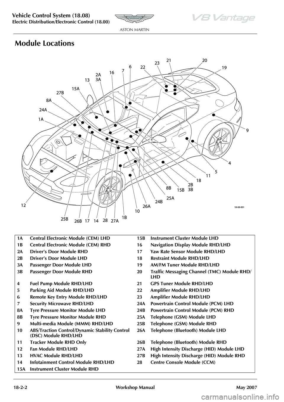
Module Locations
1A Central Electronic Module (CEM) LH D15BInstrument Cluster Module LHD
1B Central Electronic Module (CEM) RH D 16 Navigation Display Module RHD/LHD
2A Driver’s Door Module RHD 17 Yaw Rate Sensor Module RHD/LHD
2B Driver’s Door Module LHD 1 8Restraint Module RHD/LHD
3A Passenger Door Module LHD 19 AM/FM Tuner Module RHD/LHD
3B Passenger Door Module RHD 20 Traffic Messaging Channel (TMC) Module RHD/
LHD
4 Fuel Pump Module RHD/LHD 21 GPS Tuner Module RHD/LHD
5 Parking Aid Module RHD/LHD 22 Amplifier Module RHD/LHD
6 Remote Key Entry Module RHD/LH D23Amplifier Module RHD/LHD
7 Security Microwave RHD/LHD 24A Powe rtrain Control Module (PCM) LHD
8A Tyre Pressure Monitor Module LHD 24B Powertrain Control Module (PCM) RHD
8B Tyre Pressure Monitor Module RHD 25A Telephone (GSM) Module LHD
9Multi-media Module (MMM) RHD/LHD 25B Teleph one (GSM) Module RHD
10 ABS/Traction Control/Dy namic Stability Control
(DSC) Module RHD/LHD 26A Telephone (Bluetooth) Module LHD
11 Tracker Module RHD Only 26B Tel ephone (Bluetooth) Module RHD
12 Fan Module RHD/LHD 27A High Intensity Discharge (HID) Module LHD
13 HVAC Module RHD/LHD 27B High Intensity Discharge (HID) Module RHD
14 Infotainment Control Module RHD/ LHD 28 Centre Console Module (CCM)
15A Instrument Cluster Module RHD
Page 820 of 947

Electronics Training Programme
INPUTS
The Bluetooth system relies on a number of signals it receives either from the car (via hard wiring) or
the users phone (via wireless Bluetooth communication network).
The Bluetooth system will only function if the us ers mobile phone has Bluetooth enabled and it is
‘paired’ to the car. For more information refer to the user’s guide for your mobile phone.
V8 Vantage Power Supplies
Description Supplied From Source Protection
Wakeup signal Central Electronic Module Comfort Relay F68 (5 Amp)
Power supply 1 Central Electronic Module Interior Lights Relay F46 (5Amp)
Power supply 2 Central Electronic Module Interior Lights Relay F46 (5Amp)
DB9 Power Supplies
Description Supplied From Source Protection
Wakeup signal Central Electronic Module Comfort Relay F69 (5 Amp)
Power supply 1 Central Electronic Module Interior Lights Relay F46 (5Amp)
Power supply 2 Central Electronic Module Interior Lights Relay F46 (5Amp)
V8 Vantage Signal Inputs
Input Description Signal Characteristic
MIC In Input signal from microphone Varying current signal direct from microphone
Keypad Steering wheel controls input Variable resistance to earth signal
DB9 Signal Inputs
Input Description Signal Characteristic
MIC In + Input signal from microphone Varying current signal supplied via amplifier
MIC In - Input signal from microphone Varying current signal supplied via amplifier
Keypad Steering wheel controls inpu t Variable resistance to earth
Screens
Some of the signals in and out of the Bluetooth modu le require screening to avoid interference being
picked up. A signal screen is a single wire running along side t he signal wire(s) which will absorb
electro magnetic interference (EMI).
The Bluetooth module on the V8 Vantage features only one screen so as to protect the signal from the
microphone. This screen wire is simply an earth but it is also used as a datum from which to reference
the microphone signal.
The Bluetooth module used on DB9’s features two screens. One is as on the V8 Vantage but is used
only as a screen (because the microphone signal from the amplifie r has two signal wires) and no
datum is required. The second screen on the module is used to screen the ‘Lineout’ signals to the
amplifier. As with the microphone scr een this wire is connected to earth.
15
Page 873 of 947

AML EOBD System Operation Summary
Rory O’Curry Aston Martin Lagonda CONFIDENTIAL 1 May 2009
[email protected] AML EOBD Monitors 07 ROC.doc Page 27 of 43
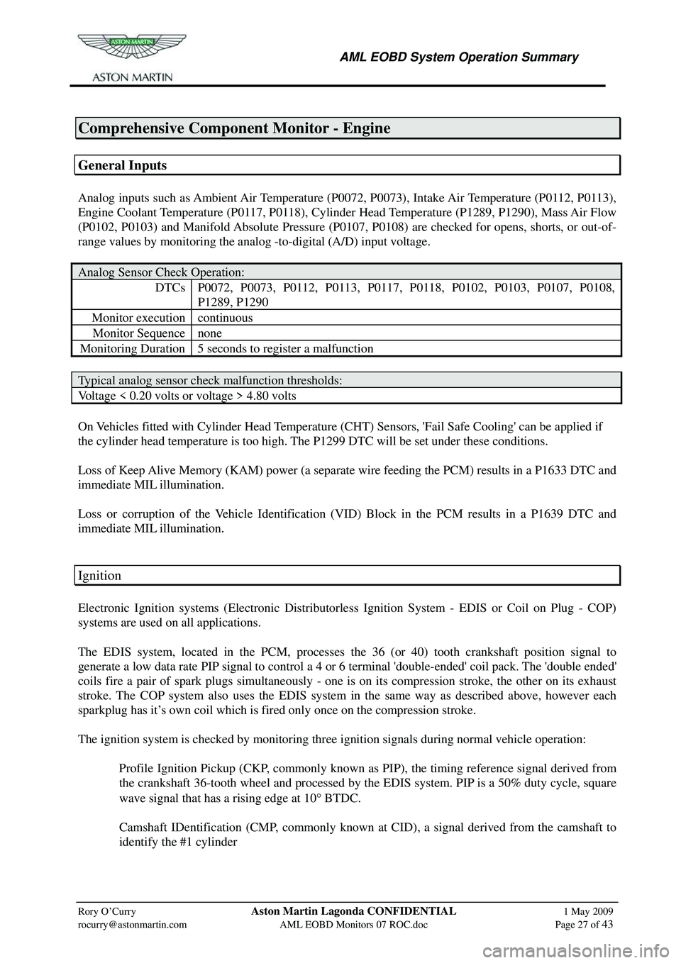
Comprehensive Component Monitor - Engine
General Inputs
Analog inputs such as Ambient Air Temperature (P0072, P0073), Intake Air Temperature (P0112, P0113),
Engine Coolant Temperature (P0117, P0118), Cylinder Head Temperature (P1289, P1290), Mass Air Flow
(P0102, P0103) and Manifold Absolute Pressure (P0107, P0108) are checked for opens, shorts, or out-of-
range values by monitoring the analog -to-digital (A/D) input voltage.
Analog Sensor Check Operation:
DTCs P0072, P0073, P0112, P0113, P0117, P0118, P0102, P0103, P0107, P0108,
P1289, P1290
Monitor execution continuous
Monitor Sequence none
Monitoring Duration 5 seconds to register a malfunction
Typical analog sensor check malfunction thresholds:
Voltage < 0.20 volts or voltage > 4.80 volts
On Vehicles fitted with Cylinder Head Temperature (CHT ) Sensors, 'Fail Safe Cooling' can be applied if
the cylinder head temperature is too high. The P1299 DTC will be set under these conditions.
Loss of Keep Alive Memory (KAM) power (a separate wire feeding the PCM) results in a P1633 DTC and
immediate MIL illumination.
Loss or corruption of the Vehicle Identification (VID) Block in the PCM results in a P1639 DTC and
immediate MIL illumination.
Ignition
Electronic Ignition systems (Electronic Distributorless Ignition System - EDIS or Coil on Plug - COP)
systems are used on all applications.
The EDIS system, located in the PCM, processes the 36 (or 40) tooth crankshaft position signal to
generate a low data rate PIP signal to control a 4 or 6 terminal 'double-ended' coil pack. The 'double ended'
coils fire a pair of spark plugs simultaneously - one is on its compression stroke, the other on its exhaust
stroke. The COP system also uses the EDIS system in the same way as described above, however each
sparkplug has it’s own coil which is fired only once on the compression stroke.
The ignition system is checked by monitoring three ignition signals during normal vehicle operation:
Profile Ignition Pickup (CKP, commonly known as PIP), the timing reference signal derived from the crankshaft 36-tooth wheel and processed by the EDIS system. PIP is a 50% duty cycle, square
wave signal that has a rising edge at 10 ° BTDC.
Camshaft IDentification (CMP, commonly known at CID), a signal derived from the camshaft to identify the #1 cylinder