ABS ASTON MARTIN V8 VANTAGE 2010 Owner's Manual
[x] Cancel search | Manufacturer: ASTON MARTIN, Model Year: 2010, Model line: V8 VANTAGE, Model: ASTON MARTIN V8 VANTAGE 2010Pages: 947, PDF Size: 43.21 MB
Page 443 of 947

Shock Absorber System (04.03)
Suspension (04.00)
May 2007 Workshop Manual 4-3-3
Front Spring-Pair-Renew
Removal
1. Raise vehicle on ramp.
2. Remove road wheel(s).
3. Disconnect ABS sensor multiplug (see Fig. 1).
4. Release sensor harness clips (x3) from upper suspension arm and vertical link (see Fig. 2).
5. Remove Torx bolts (x4) from LH and RH side securing engine cross brace and remove cross brace. 6. Remove nuts and bolts (x2 each side) from upper
suspension arm to body (see Fig. 3).
7. Position suspension arm aside (see Fig. 4).
Repair Operation Time (ROT)
Fig. 3
Allow the upper suspension arm and vertical link to fall
back, giving access to remove the spring and damper assembly
Fig. 4
Caution
Ensure that the brake flex hose is not over stretched.
Page 444 of 947

Shock Absorber System (04.03)
Suspension (04.00)4-3-4 Workshop Manual May 2007
8. Remove nuts (x3 each side) from damper top mounting and remove engine cross br ace support (see Fig. 5).
9. Remove nuts and bolts (each side) from damper lower mountings (see Fig. 6).
10. Remove spring and damper assembly.
11. Position spring compressor to spring and compress spring.
12. Hold damper shaft and remove top mounting retaining nut.
13. Remove top mounting and spring assembly.
14. Remove spring compressor from spring.
Installation
1. Clean spring and top mounting.
2. Position spring compressor to new spring and compress spring.
3. Install spring and top mounting and install and torque tighten retaining nut.
4. Remove spring compressor. 5. Install spring and damper assembly and install engine
cross brace support.
6. Install top mounting nuts (x3) each side (do not torque tighten).
7. Align damper to lower mounting and install bolts and nuts each side (do not torque tighten).
8. Position upper suspension arm and install bolts and nuts (x2) each side (do not torque tighten).
9. Connect ABS sensor multiplug and install harness clips in upper suspension ar m and vertical link.
10. Install road wheel(s).
11. Lower vehicle on ramp.
12. Torque tighten upper arm nuts and bolts.
13. Torque tighten top mounting nuts (x3) and lower mounting nut and bolt.
14. Align engine cross brace and install Torx bolts (x2).
15. Tighten Torx bolts (x4) to correct torque.
Front Damper-Pair-Renew
Removal
1. Raise vehicle on ramp.
2. Remove road wheel(s).
3. Disconnect ABS sensor multiplug.
4. Release sensor harness clips (x3) from upper suspension arm and vertical link.
5. Remove Torx bolts (x4) from LH and RH side securing
engine cross brace and remove cross brace.
6. Remove nuts and bolts (x2 each side) from upper suspension arm to body and position suspension arm
aside.
Fig. 5
Fig. 6
If removed, place the engine ba
y cross brace, complete with
mounts, in position.
Caution
Ensure that the brake flex hose is not over stretched.
Caution
Final tightening of suspen sion components must be
carried out with the suspension arms at normal ride
height. Failure to do this wi ll over stress the suspension
bushes when the suspension is deflected to maximum
upward travel.
Repair Operation Time (ROT)
ItemCode
Front Damper-Pair-Renew 04.03.AC
If removing both spring and damper units - the engine bay
cross brace will be released.
Allow the upper suspension arm and vertical link to fall back, giving access to remo ve the spring and damper
assembly.
Caution
Ensure that the brake flex hose is not over stretched.
Page 445 of 947

Shock Absorber System (04.03)
Suspension (04.00)
May 2007 Workshop Manual 4-3-5
7. Remove nuts (x3 each side) from damper top mounting and remove engine cross brace support.
8. Remove nuts and bolts each side from damper lower mountings.
9. Remove spring and damper assembly.
10. Position spring compresso r to spring and compress
spring.
11. Hold damper shaft, and remove top mounting retaining nut.
12. Remove top mounting and spring assembly.
13. Remove dust shield from rebound bumper and spring seat flange.
Installation
1. Clean spring , spring seat flange, bumper, dust shield and top mounting .
2. Install spring seat flange, rebound bumper and dust shield onto damper.
3. Install spring and top mounting and install and tighten retaining nut.
4. Remove spring compressor.
5. Install spring and damper assembly and install engine cross brace support.
6. Install top mounting nuts (x3) each side (do not torque tighten).
7. Align damper to lower mounting and install bolts and nuts each side (do not torque tighten).
8. Position upper suspension arm and install bolts and nuts (x2) each side (do not torque tighten).
9. Connect ABS sensor multiplug and install harness clips in upper suspension arm and vertical link.
10. Install road wheel(s).
11. Lower vehicle on ramp.
12. Tighten upper arm nuts an d bolts to correct torque.
13. Torque tighten top mounting nuts (x3) and lower mounting nut and bolt.
14. Align engine cross brace, install Torx bolts (x2) and
tighten Torx bolts (x4) to correct torque.
Rear Spring and Damper Assembly-Pair-
Renew
Removal
1. Open fuel filler lid and remove fuel filler cap.
2. Raise vehicle on ramp.
3. Remove road wheel(s).
4. Remove LH rear wheel arch liner (see Workshop Manual procedure 01.02.HB Wheel Arch Liner - Rear -
RH - Renew).
5. Remove RH wheel arch liner (see Workshop Manual procedure 01.02.JB Wheel Arch Liner - Rear - LH -
Renew).
6. Remove bolt securing fuel filler pipe bracket to shock
absorber mounting bracket.
7. Remove nut securing fuel fille r pipe to body and tie filler
pipe aside (see Fig. 1).
8. Disconnect ABS sensor multiplug (see Fig. 2).
If removed, place the engine
bay cross brace, complete with
mounts, in position.
Caution
Ensure that the brake flex hose is not over stretched.
Caution
Final tightening of suspension components must be
carried out with the suspensi on arms at normal ride
height. Failure to do this wi ll over stress the suspension
bushes when the suspension is deflected to maximum upward travel.
Repair Operation Time (ROT)
Page 446 of 947

Shock Absorber System (04.03)
Suspension (04.00)4-3-6 Workshop Manual May 2007
9. Release sensor harness clips (x2) from toe control arm (see Fig. 3).
10. Remove bolts (x2) each side from handbrake calliper to rear hub and release calliper an d position aside (see Fig.
4)
.
11. Remove nuts and bolts both sides from toe control arms (see Fig. 5). 12. Remove nuts and bolts each side from lower damper
mountings (see Fig. 6).
13. Remove bolts (x4) each side from damper upper mounting (see Fig. 7).
Fig. 3
Fig. 4
Fig. 5
Fig. 6
Fig. 7
Page 447 of 947
Shock Absorber System (04.03)
Suspension (04.00)
May 2007 Workshop Manual 4-3-7
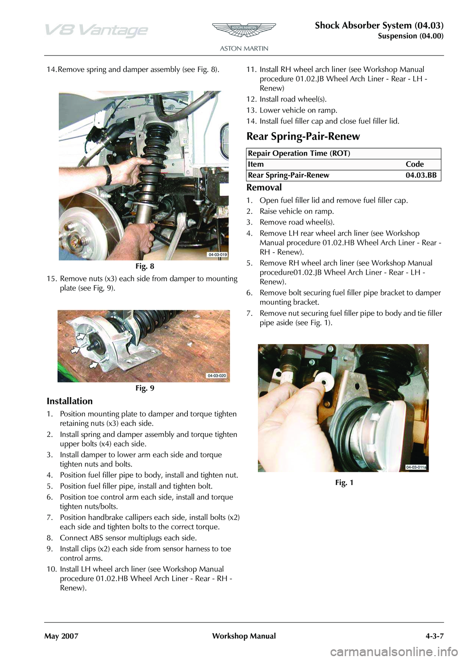
14. Remove spring and damper assembly (see Fig. 8).
15. Remove nuts (x3) each side from damper to mounting plate (see Fig, 9).
Installation
1. Position mounting plate to damper and torque tighten retaining nuts (x3) each side.
2. Install spring and damper assembly and torque tighten upper bolts (x4) each side.
3. Install damper to lower arm each side and torque tighten nuts and bolts.
4. Position fuel filler pipe to body, install and tighten nut.
5. Position fuel filler pipe, install and tighten bolt.
6. Position toe control arm each side, install and torque tighten nuts/bolts.
7. Position handbrake callipers each side, install bolts (x2) each side and tighten bolts to the correct torque.
8. Connect ABS sensor multiplugs each side.
9. Install clips (x2) each side from sensor harness to toe control arms.
10. Install LH wheel arch liner (see Workshop Manual procedure 01.02.HB Wheel Arch Liner - Rear - RH -
Renew). 11. Install RH wheel arch li
ner (see Workshop Manual
procedure 01.02.JB Wheel Arch Liner - Rear - LH -
Renew)
12. Install road wheel(s).
13. Lower vehicle on ramp.
14. Install fuel filler cap and close fuel filler lid.
Rear Spring-Pair-Renew
Removal
1. Open fuel filler lid and remove fuel filler cap.
2. Raise vehicle on ramp.
3. Remove road wheel(s).
4. Remove LH rear wheel arch liner (see Workshop Manual procedure 01.02.HB Wheel Arch Liner - Rear -
RH - Renew).
5. Remove RH wheel arch liner (see Workshop Manual procedure01.02.JB Wheel Arch Liner - Rear - LH -
Renew).
6. Remove bolt securing fuel filler pipe bracket to damper
mounting bracket.
7. Remove nut securing fuel fille r pipe to body and tie filler
pipe aside (see Fig. 1).
Fig. 8
Fig. 9
Repair Operation Time (ROT)
Page 448 of 947

Shock Absorber System (04.03)
Suspension (04.00)4-3-8 Workshop Manual May 2007
8. Disconnect ABS sensor multiplug (see Fig. 2).
9. Release sensor harness clips (x2) from toe control arm (see Fig. 3).
10. Remove bolts (x2) each side from handbrake calliper to rear hub and release calliper an d position aside (see Fig.
4)
.
11. Remove nuts and bolts both sides from toe control arms (see Fig. 5).
12. Remove nuts and bolts each side from lower damper mountings (see Fig. 6).
Fig. 2
Fig. 3
Fig. 4
Fig. 5
Fig. 6
Page 449 of 947
Shock Absorber System (04.03)
Suspension (04.00)
May 2007 Workshop Manual 4-3-9
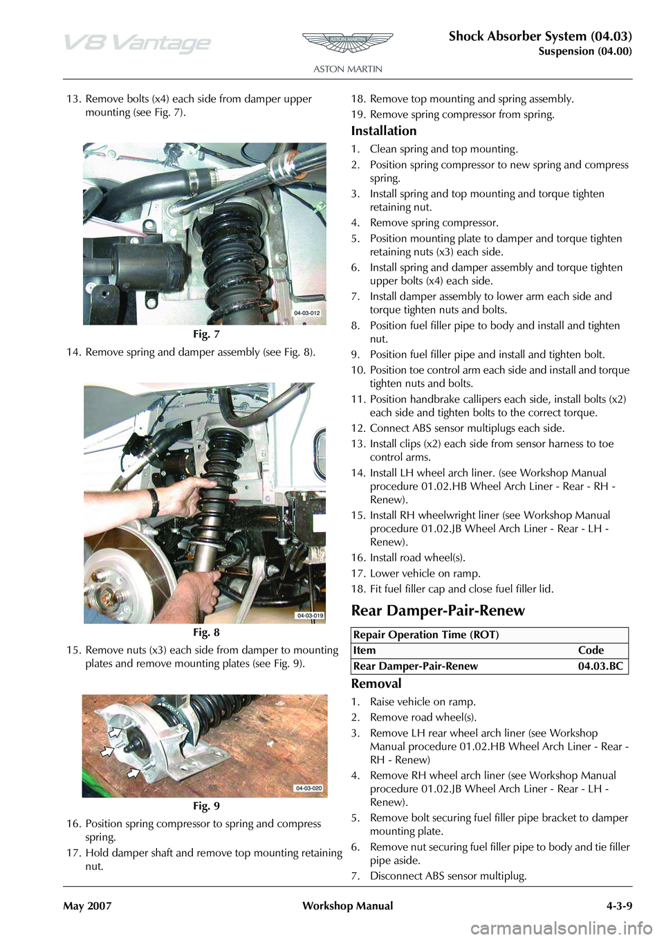
13. Remove bolts (x4) each side from damper upper mounting (see Fig. 7).
14. Remove spring and damper assembly (see Fig. 8).
15. Remove nuts (x3) each side from damper to mounting plates and remove mounting plates (see Fig. 9).
16. Position spring compresso r to spring and compress
spring.
17. Hold damper shaft and remove top mounting retaining nut. 18. Remove top mounting and spring assembly.
19. Remove spring compressor from spring.
Installation
1. Clean spring and top mounting .
2. Position spring compressor to new spring and compress
spring.
3. Install spring and top mounting and torque tighten retaining nut.
4. Remove spring compressor.
5. Position mounting plate to damper and torque tighten
retaining nuts (x3) each side.
6. Install spring and damper assembly and torque tighten upper bolts (x4) each side.
7. Install damper assembly to lower arm each side and torque tighten nuts and bolts.
8. Position fuel filler pipe to body and install and tighten nut.
9. Position fuel filler pipe and install and tighten bolt.
10. Position toe control arm each side and install and torque tighten nuts and bolts.
11. Position handbrake callipers each side, install bolts (x2) each side and tighten bolts to the correct torque.
12. Connect ABS sensor multiplugs each side.
13. Install clips (x2) each side from sensor harness to toe control arms.
14. Install LH wheel arch li ner. (see Workshop Manual
procedure 01.02.HB Wheel Arch Liner - Rear - RH -
Renew).
15. Install RH wheelwright li ner (see Workshop Manual
procedure 01.02.JB Wheel Arch Liner - Rear - LH -
Renew).
16. Install road wheel(s).
17. Lower vehicle on ramp.
18. Fit fuel filler cap and close fuel filler lid.
Rear Damper-Pair-Renew
Removal
1. Raise vehicle on ramp.
2. Remove road wheel(s).
3. Remove LH rear wheel arch liner (see Workshop Manual procedure 01.02.HB Wheel Arch Liner - Rear -
RH - Renew)
4. Remove RH wheel arch liner (see Workshop Manual procedure 01.02.JB Wheel Arch Liner - Rear - LH -
Renew).
5. Remove bolt securing fuel filler pipe bracket to damper
mounting plate.
6. Remove nut securing fuel fille r pipe to body and tie filler
pipe aside.
7. Disconnect ABS sensor multiplug.
Fig. 7
Fig. 8
Fig. 9
Repair Operation Time (ROT)
Page 450 of 947
Shock Absorber System (04.03)
Suspension (04.00)4-3-10 Workshop Manual May 2007
8. Release sensor harness clips (x2) from toe control arm.
9. Remove bolts (x2) each side from handbrake calliper to rear hub.
10. Release calliper and position aside.
11. Remove nuts and bolts both sides from toe control arms.
12. Remove nuts and bolts each side from lower damper mountings.
13. Remove bolts (x4) each side from damper upper mounting.
14. Remove spring and damper assembly.
15. Remove nuts (x3) each side from damper to mounting plates and remove mounting plates.
16. Position spring compressor to spring and compress spring.
17. Hold damper shaft and remove top mounting retaining nut.
18. Remove top mounting and spring assembly.
19. Remove dust shield, rebound bumper and spring seat flange.
Installation
1. Clean spring, spring seat flange, rebound bumper, dust
shield and top mounting .
2. Install spring seat flange, rebound bumper and dust shield onto damper.
3. Install spring and top mounting and fit and tighten retaining nut.
4. Remove spring compressor.
5. Position mounting plate to damper and torque tighten retaining nuts (x3).
6. Install spring and damper assembly and torque tighten upper bolts (x4) each side.
7. Install damper assembly to lower arm each side and torque tighten nuts and bolts.
8. Position fuel filler pipe to body and install and tighten nut.
9. Position fuel filler pipe and install and tighten bolt.
10. Position toe control arm each side and install and torque tighten nuts and bolts.
11. Position handbrake callipers each side, install bolts (x2) each side and tighten bolts to the correct torque.
12. Connect ABS sensor multiplugs each side.
13. Install clips (x2) each side from sensor harness to toe control arms.
14. Install LH wheel arch liner (see Workshop Manual procedure 01.02.HB Wheel Arch Liner - Rear - RH -
Renew).
15. Install RH wheel arch liner (see Workshop Manual procedure 01.02.JB Wheel Arch Liner - Rear - LH -
Renew)
16. Install road wheel(s).
17. Lower vehicle on ramp.
Page 460 of 947
Road Wheels and Tyres (04.04)
Suspension (04.00)4-4-10 Workshop Manual May 2007
Display Unit
The display unit provides additional features when correctly
connected to a previously installed ‘Smartire’ system. The
display unit connects directly to the front of the basic
‘Smartire’ receiver and is powered from the vehicle circuits.
The display will be fully illu minated during use but will go
into ‘Energy Saver’ mode when no activity is detected.
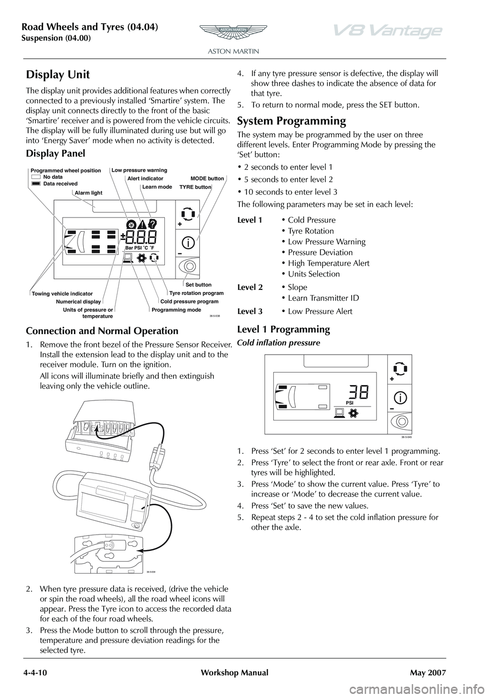
Display Panel
Connection and Normal Operation
1. Remove the front bezel of the Pressure Sensor Receiver. Install the extension lead to the display unit and to the
receiver module. Turn on the ignition.
All icons will illuminate briefly and then extinguish
leaving only the vehicle outline.
2. When tyre pressure data is received, (drive the vehicle
or spin the road wheels), all the road wheel icons will
appear. Press the Tyre icon to access the recorded data
for each of the four road wheels.
3. Press the Mode button to scroll through the pressure, temperature and pressure deviation readings for the
selected tyre. 4. If any tyre pressure sensor is defective, the display will
show three dashes to indicate the absence of data for
that tyre.
5. To return to normal mode, press the SET button.
System Programming
The system may be programmed by the user on three
different levels. Enter Progra mming Mode by pressing the
‘Set’ button:
• 2 seconds to enter level 1
• 5 seconds to enter level 2
• 10 seconds to enter level 3
The following parameters ma y be set in each level:
Level 1 Programming
Cold inflation pressure
1. Press ‘Set’ for 2 seconds to enter level 1 programming .
2. Press ‘Tyre’ to select the front or rear axle. Front or rear
tyres will be highlighted.
3. Press ‘Mode’ to show the current value. Press ‘Tyre’ to increase or ‘Mode’ to decrease the current value.
4. Press ‘Set’ to save the new values.
5. Repeat steps 2 - 4 to set the cold inflation pressure for other the axle.
Programmed wheel position No data
Data received
Alarm light Low pressure warning
Alert indicatorLearn mode MODE button
Set button
Tyre rotation program
Cold pressure program
Programming mode
Towing vehicle indicator
Numerical display
Units of pressure or temperature TYRE button
36-5-038
36-5-039
Level 1
• Cold Pressure
• Tyre Rotation
• Low Pressure Warning
• Pressure Deviation
• High Temperature Alert
•Units Selection
Level 2 •Slope
• Learn Transmitter ID
Level 3 • Low Pressure Alert
PSI
36-5-045
Page 468 of 947
Driveshaft (05.01)
Driveline (05.00)5-1-6 Workshop Manual May 2007
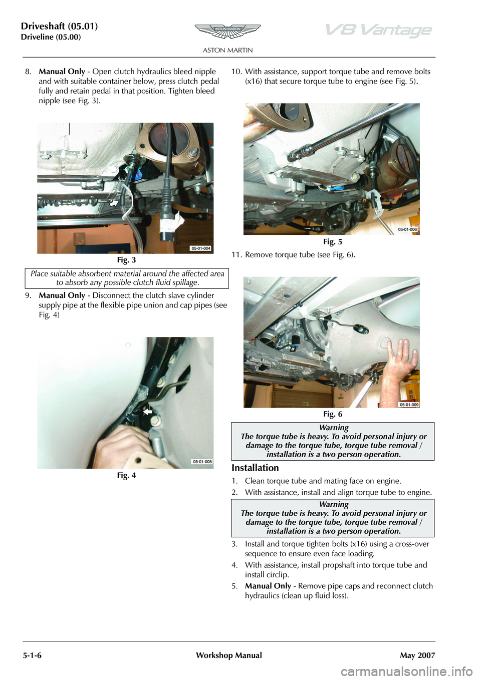
8. Manual Only - Open clutch hydraulics bleed nipple
and with suitable container below, press clutch pedal
fully and retain pedal in that position. Tighten bleed
nipple (see Fig. 3).
9. Manual Only - Disconnect the clutch slave cylinder
supply pipe at the flexible pipe union and cap pipes (see
Fig. 4) 10. With assistance, support torque tube and remove bolts
(x16) that secure torque tube to engine (see Fig. 5)
.
11. Remove torque tube (see Fig. 6).
Installation
1. Clean torque tube and mating face on engine.
2. With assistance, install and align torque tube to engine.
3. Install and torque tighten bolts (x16) using a cross-over sequence to ensure even face loading.
4. With assistance, install propshaft into torque tube and install circlip.
5. Manual Only - Remove pipe caps and reconnect clutch
hydraulics (clean up fluid loss).
Fig. 3
Place suitable absorbent material around the affected area to absorb any possible clutch fluid spillage.
Fig. 4
Fig. 5
Fig. 6
Warning
The torque tube is heavy. To avoid personal injury or damage to the torque tube, torque tube removal / installation is a two person operation.
Warning
The torque tube is heavy. To avoid personal injury or damage to the torque tube, torque tube removal /
installation is a two person operation.