check oil ASTON MARTIN V8 VANTAGE 2010 Repair Manual
[x] Cancel search | Manufacturer: ASTON MARTIN, Model Year: 2010, Model line: V8 VANTAGE, Model: ASTON MARTIN V8 VANTAGE 2010Pages: 947, PDF Size: 43.21 MB
Page 654 of 947
Instrument Cluster (13.01)
Information, Gauge and Warning (13.00)
May 2007 Workshop Manual 13-1-3
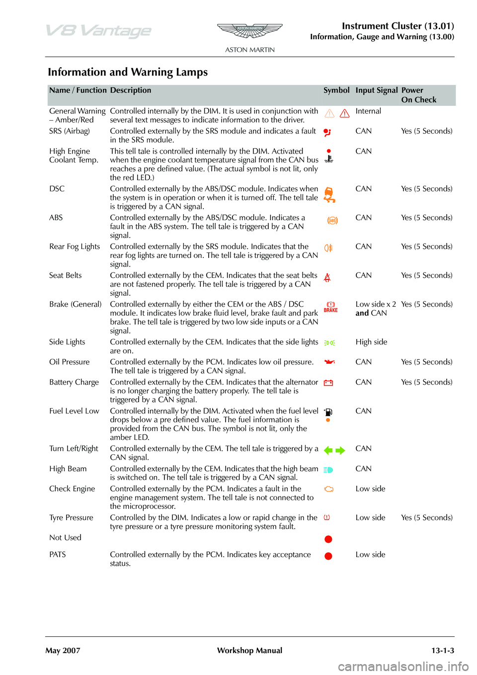
Information and Warning Lamps
Name / FunctionDescriptionSymbolInput SignalPower
On Check
General Warning
– Amber/Red Controlled internally by the DIM. It is used in conjunction with
several text messages to indicate information to the driver. Internal
SRS (Airbag) Controlled externally by the SRS module and indicates a fault in the SRS module. CAN Yes (5 Seconds)
High Engine
Coolant Temp. This tell tale is controlled internally by the DIM. Activated
when the engine coolant temperature signal from the CAN bus
reaches a pre defined value. (The
actual symbol is not lit, only
the red LED.) CAN
DSC Controlled externally by the ABS/DSC module. Indicates when the system is in operation or when it is turned off. The tell tale
is triggered by a CAN signal. CAN Yes (5 Seconds)
ABS Controlled externally by th e ABS/DSC module. Indicates a
fault in the ABS system. The tell tale is triggered by a CAN
signal. CAN Yes (5 Seconds)
Rear Fog Lights Controlled externally by the SRS module. Indicates that the
rear fog lights are turned on. The tell tale is triggered by a CAN
signal. CAN Yes (5 Seconds)
Seat Belts Controlled externally by the CEM. Indicates that the seat belts are not fastened properly. The tell tale is triggered by a CAN
signal. CAN Yes (5 Seconds)
Brake (General) Controlled externally by either the CEM or the ABS / DSC module. It indicates low brake fluid level, brake fault and park
brake. The tell tale is triggered by two low side inputs or a CAN
signal. Low side x 2
and
CAN Ye s ( 5 S e c o n d s )
Side Lights Controlled externally by th e CEM. Indicates that the side lights
are on. High side
Oil Pressure Controlled exte rnally by the PCM. Indicates low oil pressure.
The tell tale is triggered by a CAN signal. CAN Yes (5 Seconds)
Battery Charge Controlled externally by th e CEM. Indicates that the alternator
is no longer charging the battery properly. The tell tale is
triggered by a CAN signal. CAN Yes (5 Seconds)
Fuel Level Low Controlled internally by the DIM. Activated when the fuel level drops below a pre defined value. The fuel information is
provided from the CAN bus. The symbol is not lit, only the
amber LED. CAN
Turn Left/Right Controlled externally by th e CEM. The tell tale is triggered by a
CAN signal. CAN
High Beam Controlled externally by the CEM. Indicates that the high beam is switched on. The tell tale is triggered by a CAN signal. CAN
Check Engine Controlled externally by the PCM. Indicates a fault in the engine management system. The te ll tale is not connected to
the microprocessor. Low side
Tyre Pressure Controlled by the DIM. In dicates a low or rapid change in the
tyre pressure or a tyre pressure monitoring system fault. Low side Yes (5 Seconds)
Not Used
PATS Controlled externally by the PCM. Indicates key acceptance status. Low side
Page 751 of 947
Maintenance Schedules
Appendix & Glossary20-1-12 Workshop Manual May 2007
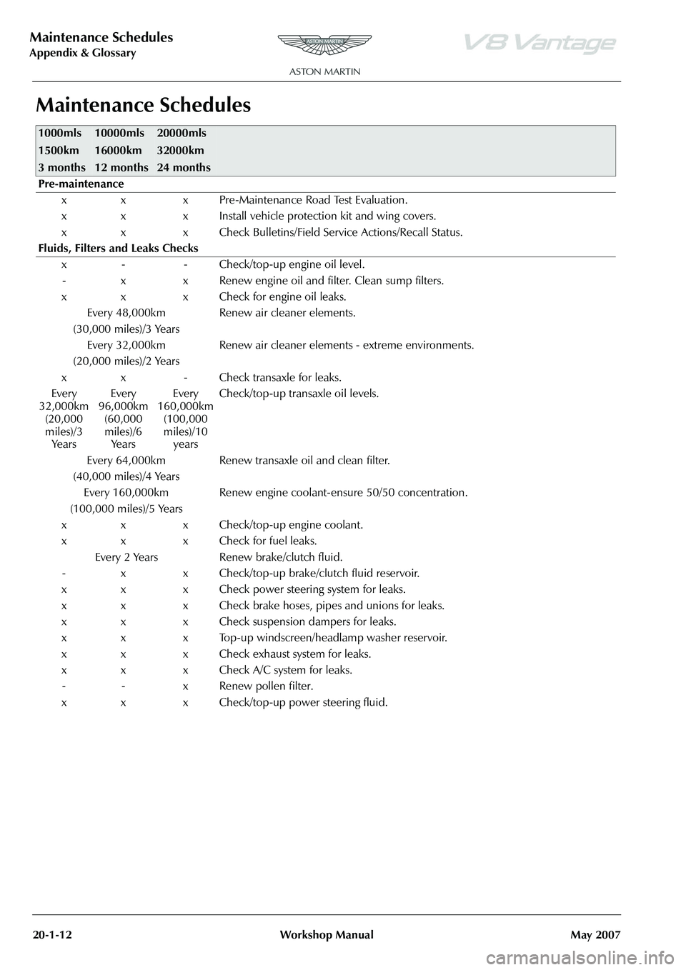
Maintenance Schedules
1000mls
1500km
3 months10000mls
16000km
12 months20000mls
32000km
24 months
Pre-maintenance
x x x Pre-Maintenance Road Test Evaluation.
x x x Install vehicle protection kit and wing covers.
x x x Check Bulletins/Field Service Actions/Recall Status.
Fluids, Filters and Leaks Checks x - - Check/top-up engine oil level.- x x Renew engine oil and filter. Clean sump filters.
x x x Check for engine oil leaks. Every 48,000km
(30,000 miles)/3 Years Renew air cleaner elements.
Every 32,000km
(20,000 miles)/2 Years Renew air cleaner elements - extreme environments.
x x - Check transaxle for leaks.
Every
32,000km (20,000
miles)/3 Ye a r s Every
96,000km (60,000
miles)/6 Ye a r s Every
160,000km (100,000
miles)/10 years Check/top-up transaxle oil levels.
Every 64,000km
(40,000 miles)/4 Years Renew transaxle oil and clean filter.
Every 160,000km
(100,000 miles)/5 Years Renew engine coolant-ensure 50/50 concentration.
x x x Check/top-up engine coolant.
x x x Check for fuel leaks. Every 2 Years Renew brake/clutch fluid.
- x x Check/top-up brake/clutch fluid reservoir.
x x x Check power steering system for leaks.
x x x Check brake hoses, pipes and unions for leaks.
x x x Check suspension dampers for leaks.
x x x Top-up windscreen/headlamp washer reservoir.
x x x Check exhaust system for leaks.
x x x Check A/C system for leaks. - - x Renew pollen filter.
x x x Check/top-up power steering fluid.
Page 871 of 947
AML EOBD System Operation Summary
Rory O’Curry Aston Martin Lagonda CONFIDENTIAL 1 May 2009
[email protected] AML EOBD Monitors 07 ROC.doc Page 25 of 43
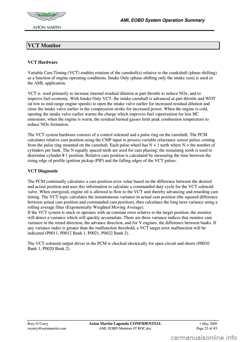
VCT Monitor
Variable Cam Timing System Monitor
VCT Hardware
Variable Cam Timing (VCT) enables rotation of the camshaft(s) relative to the crankshaft (phase-shifting)
as a function of engine operating conditions. Intake Only (phase-shifting only the intake cam) is used in
the AML application.
VCT is used primarily to increase internal residua l dilution at part throttle to reduce NOx, and to
improve fuel economy. With Intake Only VCT, the in take camshaft is advanced at part throttle and WOT
(at low to mid-range engine speeds) to open the in take valve earlier for increased residual dilution and
close the intake valve earlier in the compression stroke for increased power. When the engine is cold,
opening the intake valve earlier warms the charge which improves fuel vaporization for less HC
emissions; when the engine is warm, the residua l burned gasses limit peak combustion temperature to
reduce NOx formation.
The VCT system hardware consists of a contro l solenoid and a pulse ring on the camshaft. The PCM
calculates relative cam position using the CMP input to process variable reluctance sensor pulses coming
from the pulse ring mounted on the camshaft. Each pul se wheel has N + 1 teeth where N = the number of
cylinders per bank. The N equally spaced teeth are used for cam phasing; the remaining tooth is used to
determine cylinder # 1 position. Relative cam position is calculated by measuring the time between the
rising edge of profile ignition pickup (PIP ) and the falling edges of the VCT pulses.
VCT Diagnostic
The PCM continually calculates a cam position error value based on the difference between the desired
and actual position and uses this information to cal culate a commanded duty cycle for the VCT solenoid
valve. When energized, engine oil is allowed to flow to the VCT unit thereby advancing and retarding cam
timing. The VCT logic calculates the instantaneous va riance in actual cam position (the squared difference
between actual cam position and commanded cam position), then calculates the long term variance using a
rolling average filter (Exponentially Weighted Moving Average).
If the VCT system is stuck or operates with an consta nt error relative to the target position, the monitor
will detect a variance which will quickly accumulate. There are three variance indices that monitor cam
variance in the retard direction, the advance directi on, and for V engines, the difference between banks. If
any variance index is greater than the malfunction threshold, a VCT target error malfunction will be
indicated (P0011, P0012 Bank 1, P0021, P0022 Bank 2).
The VCT solenoid output driver in the PCM is check ed electrically for open circuit and shorts (P0010
Bank 1, P0020 Bank 2).
VCT Monitor Operation:
Page 873 of 947
AML EOBD System Operation Summary
Rory O’Curry Aston Martin Lagonda CONFIDENTIAL 1 May 2009
[email protected] AML EOBD Monitors 07 ROC.doc Page 27 of 43
Comprehensive Component Monitor - Engine
General Inputs
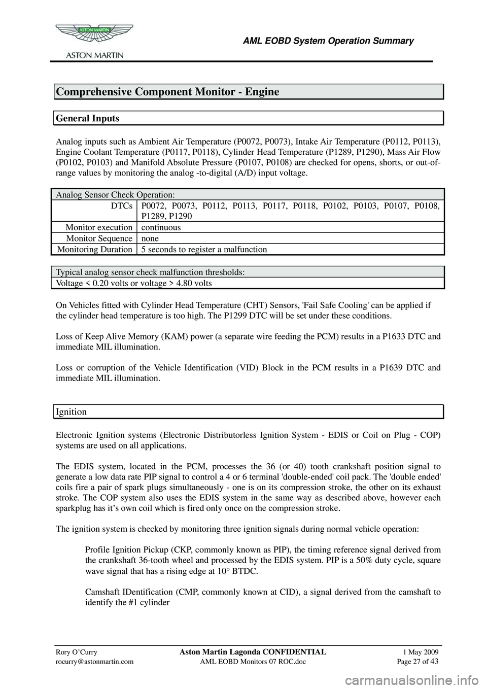
Analog inputs such as Ambient Air Temperature (P0072, P0073), Intake Air Temperature (P0112, P0113),
Engine Coolant Temperature (P0117, P0118), Cylinder Head Temperature (P1289, P1290), Mass Air Flow
(P0102, P0103) and Manifold Absolute Pressure (P0107, P0108) are checked for opens, shorts, or out-of-
range values by monitoring the analog -to-digital (A/D) input voltage.
Analog Sensor Check Operation:
DTCs P0072, P0073, P0112, P0113, P0117, P0118, P0102, P0103, P0107, P0108,
P1289, P1290
Monitor execution continuous
Monitor Sequence none
Monitoring Duration 5 seconds to register a malfunction
Typical analog sensor check malfunction thresholds:
Voltage < 0.20 volts or voltage > 4.80 volts
On Vehicles fitted with Cylinder Head Temperature (CHT ) Sensors, 'Fail Safe Cooling' can be applied if
the cylinder head temperature is too high. The P1299 DTC will be set under these conditions.
Loss of Keep Alive Memory (KAM) power (a separate wire feeding the PCM) results in a P1633 DTC and
immediate MIL illumination.
Loss or corruption of the Vehicle Identification (VID) Block in the PCM results in a P1639 DTC and
immediate MIL illumination.
Ignition
Electronic Ignition systems (Electronic Distributorless Ignition System - EDIS or Coil on Plug - COP)
systems are used on all applications.
The EDIS system, located in the PCM, processes the 36 (or 40) tooth crankshaft position signal to
generate a low data rate PIP signal to control a 4 or 6 terminal 'double-ended' coil pack. The 'double ended'
coils fire a pair of spark plugs simultaneously - one is on its compression stroke, the other on its exhaust
stroke. The COP system also uses the EDIS system in the same way as described above, however each
sparkplug has it’s own coil which is fired only once on the compression stroke.
The ignition system is checked by monitoring three ignition signals during normal vehicle operation:
Profile Ignition Pickup (CKP, commonly known as PIP), the timing reference signal derived from the crankshaft 36-tooth wheel and processed by the EDIS system. PIP is a 50% duty cycle, square
wave signal that has a rising edge at 10 ° BTDC.
Camshaft IDentification (CMP, commonly known at CID), a signal derived from the camshaft to identify the #1 cylinder
Page 874 of 947
AML EOBD System Operation Summary
Rory O’Curry Aston Martin Lagonda CONFIDENTIAL 1 May 2009
[email protected] AML EOBD Monitors 07 ROC.doc Page 28 of 43
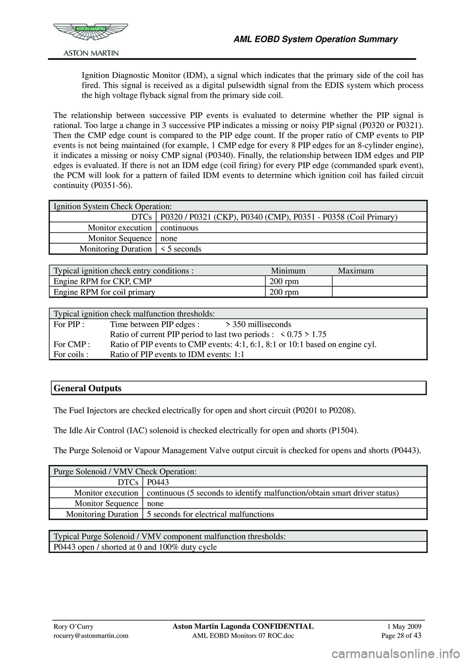
Ignition Diagnostic Monitor (IDM), a signal which indicates that the primary side of the coil has
fired. This signal is received as a digital pulsewidth signal from the EDIS system which process
the high voltage flyback signal from the primary side coil.
The relationship between successive PIP events is ev aluated to determine whether the PIP signal is
rational. Too large a change in 3 successive PIP indicates a missing or noisy PIP signal (P0320 or P0321).
Then the CMP edge count is compared to the PIP e dge count. If the proper ratio of CMP events to PIP
events is not being maintained (for example, 1 CMP e dge for every 8 PIP edges for an 8-cylinder engine),
it indicates a missing or noisy CMP signal (P0340). Finally, the relationship between IDM edges and PIP
edges is evaluated. If there is not an IDM edge (co il firing) for every PIP edge (commanded spark event),
the PCM will look for a pattern of failed IDM events to determine which ignition coil has failed circuit
continuity (P0351-56).
Ignition System Check Operation:
DTCs P0320 / P0321 (CKP), P0340 (CMP), P0351 - P0358 (Coil Primary)
Monitor execution continuous
Monitor Sequence none
Monitoring Duration < 5 seconds
Typical ignition check entry conditions : Minimum Maximum
Engine RPM for CKP, CMP 200 rpm
Engine RPM for coil primary 200 rpm
Typical ignition check malfunction thresholds:
For PIP : Time between PIP edges : > 350 milliseconds
Ratio of current PIP period to last two periods : < 0.75 > 1.75
For CMP : Ratio of PIP events to CMP events: 4:1, 6:1, 8:1 or 10:1 based on engine cyl.
For coils : Ratio of PIP events to IDM events: 1:1
General Outputs
The Fuel Injectors are checked electrically for open and short circuit (P0201 to P0208).
The Idle Air Control (IAC) solenoid is checked electrically for open and shorts (P1504).
The Purge Solenoid or Vapour Management Valve output circuit is checked for opens and shorts (P0443).
Purge Solenoid / VMV Check Operation:
DTCsP0443
Monitor execution continuous (5 seconds to identify malfunction/obtain smart driver status)
Monitor Sequencenone
Monitoring Duration 5 seconds for electrical malfunctions
Typical Purge Solenoid / VMV component malfunction thresholds:
P0443 open / shorted at 0 and 100% duty cycle
Page 883 of 947
AML EOBD System Operation Summary
Rory O’Curry Aston Martin Lagonda CONFIDENTIAL 1 May 2009
[email protected] AML EOBD Monitors 07 ROC.doc Page 37 of 43
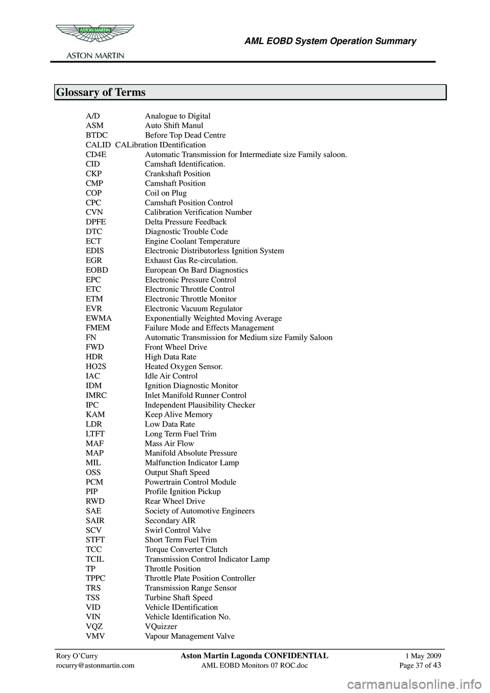
Glossary of Terms
A/D Analogue to Digital
ASM Auto Shift Manul
BTDC Before Top Dead Centre
CALID CALibration IDentification
CD4E Automatic Transmission for Intermediate size Family saloon.
CID Camshaft Identification.
CKP Crankshaft Position
CMP Camshaft Position
COP Coil on Plug
CPC Camshaft Position Control
CVN Calibration Verification Number
DPFE Delta Pressure Feedback
DTC Diagnostic Trouble Code
ECT Engine Coolant Temperature
EDIS Electronic Distributorless Ignition System
EGR Exhaust Gas Re-circulation.
EOBD European On Bard Diagnostics
EPC Electronic Pressure Control
ETC Electronic Throttle Control
ETM Electronic Throttle Monitor
EVR Electronic Vacuum Regulator
EWMA Exponentially Weighted Moving Average
FMEM Failure Mode and Effects Management
FN Automatic Transmission for Medium size Family Saloon
FWD Front Wheel Drive
HDR High Data Rate
HO2S Heated Oxygen Sensor.
IAC Idle Air Control
IDM Ignition Diagnostic Monitor
IMRC Inlet Manifold Runner Control
IPC Independent Plausibility Checker
KAM Keep Alive Memory
LDR Low Data Rate
LTFT Long Term Fuel Trim
MAF Mass Air Flow
MAP Manifold Absolute Pressure
MIL Malfunction Indicator Lamp
OSS Output Shaft Speed
PCM Powertrain Control Module
PIP Profile Ignition Pickup
RWD Rear Wheel Drive
SAE Society of Automotive Engineers
SAIR Secondary AIR
SCV Swirl Control Valve
STFT Short Term Fuel Trim
TCC Torque Converter Clutch
TCIL Transmission Control Indicator Lamp
TP Throttle Position
TPPC Throttle Plate Position Controller
TRS Transmission Range Sensor
TSS Turbine Shaft Speed
VID Vehicle IDentification
VIN Vehicle Identification No.
VQZ VQuizzer
VMV Vapour Management Valve
Page 900 of 947
Aston Martin V8 Vantage 2009 MY EOBD DocumentationAston Martin/Ford Confidential
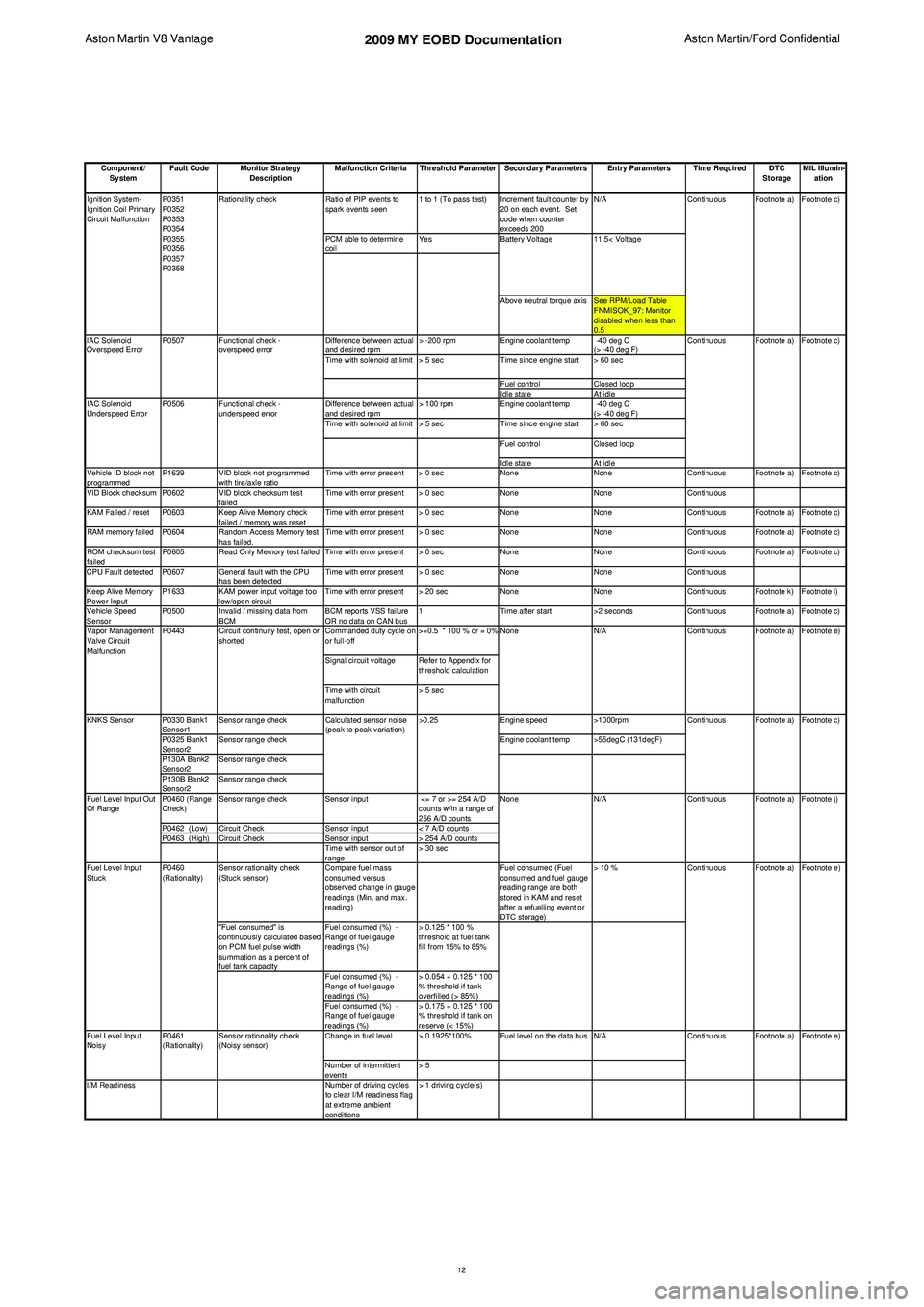
Component/ System Fault Code Monitor Strategy
Description Malfunction Criteria Threshold Parameter Secondary Parameters Entry Parameters Time Required DTC
StorageMIL Illumin-
ation
Ratio of PIP events to
spark events seen 1 to 1 (To pass test) Increment fault counter by
20 on each event. Set
code when counter
exceeds 200 N/A
PCM able to determine
coil Yes
Above neutral torque axis See RPM/Load Table FNMISOK_97: Monitor
disabled when less than
0.5
Difference between actual
and desired rpm > -200 rpm
Engine coolant temp -40 deg C
(> -40 deg F)
Time with solenoid at limit > 5 sec Time since engine start > 60 sec
Fuel control Closed loop
Idle state At idle
Difference between actual
and desired rpm > 100 rpm
Engine coolant temp -40 deg C
(> -40 deg F)
Time with solenoid at limit > 5 sec Time since engine start > 60 sec
Fuel control Closed loop
Idle state At idle
Vehicle ID block not
programmed P1639 VID block not programmed
with tire/axle ratio Time with error present > 0 sec
NoneNoneContinuous Footnote a) Footnote c)
VID Block checksum P0602 VID block checksum test failedTime with error present > 0 sec
NoneNoneContinuous
KAM Failed / reset P0603 Keep Alive Memory check failed / memory was resetTime with error present > 0 sec
NoneNoneContinuous Footnote a) Footnote c)
RAM memory failed P0604 Random Access Memory test has failed.Time with error present > 0 sec
NoneNoneContinuous Footnote a) Footnote c)
ROM checksum test
failed P0605 Read Only Memory test failed Time with error present > 0 sec
NoneNoneContinuous Footnote a) Footnote c)
CPU Fault detected P0607 General fault with the CPU has been detectedTime with error present > 0 sec
NoneNoneContinuous
Keep Alive Memory
Power Input P1633 KAM power input voltage too
low/open circuit Time with error present > 20 sec
NoneNoneContinuous Footnote k) Footnote i)
Vehicle Speed
Sensor P0500 Invalid / missing data from
BCM BCM reports VSS failure
OR no data on CAN bus1
Time after start >2 secondsContinuous Footnote a) Footnote c)
Commanded duty cycle on
or full-off >=0.5 * 100 % or = 0%
Signal circuit voltage Refer to Appendix for threshold calculation
Time with circuit
malfunction > 5 sec
P0330 Bank1
Sensor1 Sensor range check
Engine speed>1000rpm
P0325 Bank1
Sensor2 Sensor range check
Engine coolant temp >55degC (131degF)
P130A Bank2
Sensor2 Sensor range check
P130B Bank2
Sensor2 Sensor range check
P0460 (Range
Check) Sensor range check
Sensor input <= 7 or >= 254 A/D
counts w/in a range of
256 A/D counts
P0462 (Low) Circuit Check Sensor input< 7 A/D counts
P0463 (High) Circuit Check Sensor input> 254 A/D counts
Time with sensor out of
range > 30 sec
Sensor rationality check
(Stuck sensor) Compare fuel mass
consumed versus
observed change in gauge
readings (Min. and max.
reading) Fuel consumed (Fuel
consumed and fuel gauge
reading range are both
stored in KAM and reset
after a refuelling event or
DTC storage)> 10 %
"Fuel consumed" is
continuously calculated based
on PCM fuel pulse width
summation as a percent of
fuel tank capacity Fuel consumed (%) -
Range of fuel gauge
readings (%)
> 0.125 * 100 %
threshold at fuel tank
fill from 15% to 85%
Fuel consumed (%) -
Range of fuel gauge
readings (%) > 0.054 + 0.125 * 100
% threshold if tank
overfilled (> 85%)
Fuel consumed (%) -
Range of fuel gauge
readings (%) > 0.175 + 0.125 * 100
% threshold if tank on
reserve (< 15%)
Change in fuel level > 0.1925*100% Fuel level on the data bus N/A
Number of intermittent
events > 5
I/M Readiness Number of driving cycles
to clear I/M readiness flag
at extreme ambient
conditions > 1 driving cycle(s) Footnote e)
Footnote a)
Footnote c)
Footnote a) Footnote j) Footnote e)
Fuel Level Input
Noisy Continuous Footnote a)
Continuous Footnote a)
P0461
(Rationality) Sensor rationality check
(Noisy sensor)
Fuel Level Input
Stuck
P0460
(Rationality) Continuous
N/A Continuous
Calculated sensor noise
(peak to peak variation)
>0.25
KNKS Sensor
Fuel Level Input Out
Of Range NoneFootnote a) Footnote e)
Vapor Management
Valve Circuit
Malfunction P0443 Circuit continuity test, open or
shorted None
N/A Continuous
11.5< Voltage
Ignition System-
Ignition Coil Primary
Circuit Malfunction
IAC Solenoid
Underspeed Error P0507
P0506
Functional check -
overspeed error
Functional check -
underspeed error
IAC Solenoid
Overspeed Error
Footnote a) Footnote c)
Continuous
P0351
P0352
P0353
P0354
P0355
P0356
P0357
P0358
Rationality check
Continuous Footnote a) Footnote c)
Battery Voltage
12
Page 924 of 947
Aston Martin V12 Family
2009 MY V12 Family EOBDincl. V12 Vantage
Aston Martin/Ford Confidential
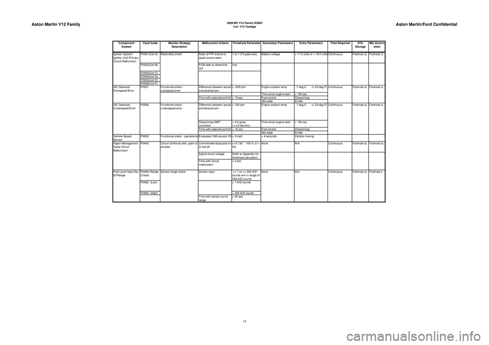
Component/ System Fault Code Monitor Strategy
Description Malfunction Criteria Threshold Parameter Secondary Parameters Entry Parameters Time Required DTC
StorageMIL Illumin-
ation
P0351(Coil A) Ratio of PIP events to
spark events seen 1 to 1 (To pass test) Battery voltage
> 11.0 volts or < 18.0 volts Continuous Footnote a) Footnote c)
P0352(Coil B) PCM able to determine
coil Yes
P0353(Coil C)
P0354(Coil D)
P0355(Coil E)
P0356(Coil F) Functional check -
overspeed error Difference between actual
and desired rpm> -200 rpm
Engine coolant temp -7 deg C (> 20 deg F)
Time since engine start > 100 sec
Time with solenoid at limit > 15 sec Fuel controlClosed loop
Idle state At idle
Difference between actual
and desired rpm > 100 rpm
Engine coolant temp -7 deg C (> 20 deg F)
Closed loop MAF
correction > 4.5 g/sec
(> 0.6 lbs/min)Time since engine start > 100 sec
Time with solenoid at limit > 10 sec Fuel controlClosed loop
Idle state At idle
Vehicle Speed
Sensor P0500 Functional check - operational Evaluates CAN source VS > 3 mph
> 4 secondsVehicle moving
Commanded dutycycle on
or full-off >=0.135 * 100 % or =
0%None
N/A Continuous Footnote a) Footnote e)
Signal circuit voltage Refer to Appendix for threshold calculation
Time with circuit
malfunction > 5 sec
P0460 (Range
Check) Sensor input
<= 7 or >= 254 A/D
counts w/in a range of
256 A/D counts
P0462 (Low) < 7 A/D counts
P0463 (High) > 254 A/D counts
Time with sensor out of
range > 30 sec N/A
Continuous Footnote a) Footnote j)
Fuel Level Input Out
Of Range Sensor range check
None
Vapor Management
Valve Circuit
Malfunction
P0443 Circuit continuity test, open or
shorted Footnote a) Footnote c)
IAC Solenoid
Underspeed Error P0506 Functional check -
underspeed error Continuous
IAC Solenoid
Overspeed Error
P0507
Continuous Footnote a) Footnote c)
Ignition System-
Ignition Coil Primary
Circuit Malfunction
Rationality check
13
Page 936 of 947
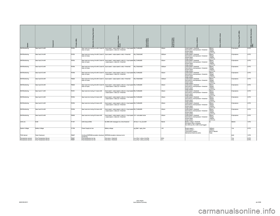
System
Component
P Codes (AML)
Malfunction Strategy Description
Malfunction Criteria
(Fault)
Fault condition
(Internal labels)
Threshold Value
(Fault condition)
Entry conditions
Entry conditions values
Filter Time to log DTC (AML)
EMS controlled MIL Illumination
(AML)
(input speed - output speed x ratio
) (t) - (input speed
- output speed x ratio) (0) < threshold ND_TUNSUEB
<30rpmoutput speed > threshold
transmission oil temperature > threshold
engine speed
range position 256rpm
10DegC
1200rpm
no P, R, N5 Symptoms
2 DTC
Shift Monitoring Gear load 4-5 shift P0784Gear load error during 4-5 shift. Clutch B
does not close. (input speed - output speed x ratio) > threshold ND_TSUEA45Z
>300rpmoutput speed > threshold
transmission oil temperature > threshold
engine speed
range position 256rpm
10DegC
1200rpm
no P, R, N5 Symptoms
2 DTC
Shift Monitoring Gear load 4-5 shift P0784Gear load error during 4-5 shift. Clutch E
does not open.
(input speed - output speed x ratio
) (t) - (input speed
- output speed x ratio) (0) < threshold ND_TUNSUEB
<30rpmoutput speed > threshold
transmission oil temperature > threshold
engine speed
range position 256rpm
10DegC
1200rpm
no P, R, N5 Symptoms
2 DTC
Shift Monitoring Gear load 5-6 shift P0829Gear load error during 5-6 shift. Clutch C
does not close. (input speed - output speed x ratio) > threshold ND_TSUEA56Z
>300rpmoutput speed > threshold
transmission oil temperature > threshold
engine speed
range position 256rpm
10DegC
1200rpm
no P, R, N5 Symptoms
2 DTC
Shift Monitoring Gear load 5-6 shift P0829Gear load error during 5-6 shift. Clutch B
does not open.
(input speed - output speed x ratio
) (t) - (input speed
- output speed x ratio) (0) < threshold ND_TUNSUEB
<30rpmoutput speed > threshold
transmission oil temperature > threshold
engine speed
range position 256rpm
10DegC
1200rpm
no P, R, N5 Symptoms
2 DTC
Shift Monitoring Gear load 2-1 shift P0781Gear load error during 2-1 down shift.
(input speed - output speed x ratio
) (t) - (input speed
- output speed x ratio) (0) < threshold ND_TUNSUEB
<30rpmoutput speed > threshold
transmission oil temperature > threshold
engine speed
range position 256rpm
10DegC
1200rpm
no P, R, N5 Symptoms
2 DTC
Shift Monitoring Gear load 3-2 shift P0782Gear load error during 3-2 down shift.
(input speed - output speed x ratio
) (t) - (input speed
- output speed x ratio) (0) < threshold ND_TUNSUEB
<30rpmoutput speed > threshold
transmission oil temperature > threshold
engine speed
range position 256rpm
10DegC
1200rpm
no P, R, N5 Symptoms
2 DTC
Shift Monitoring Gear load 4-3 shift P0783Gear load error during 4-3 down shift.
(input speed - output speed x ratio
) (t) - (input speed
- output speed x ratio) (0) < threshold ND_TUNSUEB
<30rpmoutput speed > threshold
transmission oil temperature > threshold
engine speed
range position 256rpm
10DegC
1200rpm
no P, R, N5 Symptoms
2 DTC
Shift Monitoring Gear load 5-4 shift P0784Gear load error during 5-4 down shift.
(input speed - output speed x ratio
) (t) - (input speed
- output speed x ratio) (0) < threshold ND_TUNSUEB
<30rpmoutput speed > threshold
transmission oil temperature > threshold
engine speed
range position 256rpm
10DegC
1200rpm
no P, R, N5 Symptoms
2 DTC
Shift Monitoring Gear load 6-5 shift. P0829Gear load error during 6-5 down shift.
(input speed - output speed x ratio
) (t) - (input speed
- output speed x ratio) (0) < threshold -30 > calculated value
<30rpmoutput speed > threshold
transmission oil temperature > threshold
engine speed
range position 256rpm
10DegC
1200rpm
no P, R, N5 Symptoms
2 DTC
CAN Link ECM P1797CAN timeout EMS No EMS CAN messages for a time threshold off time >= tcn_EcmOff 750mSBattery voltage > threshold
No engine crank in progress
No CAN bus off or CAN lvl fault logged 9v
500mS1 DTC
System Voltage Battery Voltage P1789Power Supply too low Battery voltage ugt_Batt < ugts_Ulow< 9VEngine speed >
Turbine speed >
Transmission position
Mechanical limphome active 1400rpm
1400rpm
Park or Neutral
False1.0s
2 DTC
TCM Internal Flash Checksum P062FContinual EEPROM emulation checksum
monitoring EEPROM emulation checksum error
0mS1 DTC
Temperature sensors Chip Temperature Sensor P0667 Chip temperature too big Chip temp > threshold ucu_Chip > utmso_CcuChip4.95v 1.5s2 DTC
Temperature sensors Chip Temperature Sensor P0667 Chip temperature too low Chip temp < threshold ucu_Chip < utmsu_CcuChip0.1v 1.5s2 DTC
8ASXV05.9VH1 Aston Martin
Auto Gearbox Summary Jan 2008