ABS ASTON MARTIN V8 VANTAGE 2010 Workshop Manual
[x] Cancel search | Manufacturer: ASTON MARTIN, Model Year: 2010, Model line: V8 VANTAGE, Model: ASTON MARTIN V8 VANTAGE 2010Pages: 947, PDF Size: 43.21 MB
Page 3 of 947
Contents
Issue 5, January 2010 Workshop Manual 0-0-3
V8 Vantage Workshop Manual
Contents
IntroductionWelcome .............................................................. 0-0-6
Safety Precautions ................................................. 0-0-7
Lifting and Jacking ................................................. 0-0-9
Vehicle Recovery ................................................ 0-0-10
Vehicle Identification Number ............................ 0-0-11
Body System (01.00) Body Structure (01.01) .......................................... 1-1-4
Front End System (01.02) ...................................... 1-2-1
Body Closures (01.03) ........................................... 1-3-1
Interior Trim (01.05) ............................................. 1-4-1
Exterior Trim (01.08) ............................................. 1-8-1
Mirrors (01.09) ...................................................... 1-9-1
Seating (01.10).................................................... 1-10-1
Glass, Frame and Mechanism (01.11) .................. 1-11-1
Instrument Panel (IP) (01.12) . .............................. 1-12-1
Handles and Lock Mechanisms (01.14) ............... 1-14-1
Wipers and Washer System (01.16)..................... 1-16-1
Convertible Roof and Roof Opening
Subsystem (01.17)................ ...............................1-17-1
Bumpers (01.19) ................................................. 1-19-1
Restraining Devices (01.20) .... ............................. 1-20-1
Frame and Mounting (02.00) Subframes (02.03) ................................................. 2-1-2
Engine System (03.00) Engine Assembly....................................................3-0-3
Engine Structure (03.01)........................................ 3-1-1
Lubrication System (03.02).................................... 3-2-1
Cooling System (03.03) ......................................... 3-3-1
Fuel Charging System (03.04) ................................ 3-4-1
Accessory Drive System (03.05)............................. 3-5-1
Engine Cranking System (03. 06) ............................ 3-6-1
Valve Train (03.09) ............................................... 3-9-1
Engine Sealing (03.10)......................................... 3-10-1
Power Conversion (03.11)................................... 3-11-1
Evaporative Emissions (03.13) ............................. 3-11-1
Engine Management System (0 3.14).................... 3-14-1
Throttle Control (03.16) ...... ................................ 3-16-1
Foot Operated Control (03.18)............................ 3-18-1
Suspension (04.00) Road Wheel Alignment (04.00) ............................. 4-0-2
Front Suspension (04.01)....................................... 4-1-1
Rear Suspension (04.02)........................................ 4-2-1
Shock Absorber System (04.03) ............................. 4-3-1
Road Wheels and Tyres (04.04) ............................ 4-4-1
Driveline (05.00) Driveshaft (05.01) ................................................. 5-1-2
Halfshafts (05.05) .................................................. 5-2-1 Brake System (06.00)
Front Disc Brake (06.03) ....................................... 6-3-2
Rear Disc Brakes (06.04) ....................................... 6-4-1
Hand Brake (06.05) .............................................. 6-5-1
Brake Actuation System (06.06 ) ............................ 6-6-1
Power Brake System (06.07) ................................. 6-7-1
Anti-lock Braking System (06.09)........................... 6-9-1
Transmission (07.00) Transmission Cooling (07.02) ................................ 7-0-2
Manual Transmission (07.03) ................................ 7-3-1
Automatic Control System (07.05)......................... 7-5-1
Manual Control System (07.06) ............................. 7-6-1
Automatic Shifting Subsytem (07.11) .................. 7-11-1
Clutch (08.00) Clutch Controls (08.02) ......................................... 8-1-2
Exhaust (09.00) Exhaust Overview ................................................. 9-1-2
Silencer Assembly (09.01) ..................................... 9-1-3
Pipes and Supports (09.03) ................................... 9-2-1
Exhaust Protection (09.04) .................................... 9-3-1
Fuel (10.00) Fuel Tank and Lines (10.01) ................................ 10-1-2
Steering (11.00) Steering Gear (11.01) .......................................... 11-1-2
Power Steering (11.02)........................................ 11-2-1
Steering Column (11.04) ..................................... 11-4-1
Steering Column Switches (1 1.05) ....................... 11-5-1
Steering Wheel (11.06) ....................................... 11-6-1
Climate Control (12.00) Body Ventilation system (12.01) .......................... 12-1-2
Heater System (12.02) ........................................ 12-2-1
Air Conditioning (A/C) System (12.03) ................. 12-3-1
Information, Gauge and Warning (13.00) Instrument Cluster (13.01) .................................. 13-1-2
Power Supply (14.00) Battery System (14.01) ........................................ 14-1-2
Alternator and Regulator System (14.02) ............. 14-2-1
Vehicle Entertainment (15.00) Audio System (15.01)................................ ..........15-1-2
Antenna (15.02).................................................. 15-2-1
Vacuum Distribution (16.00) Body Vacuum System (16.01) ............................. 16-1-2
Lighting (17.00) Front Lights (17.01) ............................................. 17-1-2
Interior Lighting (17.02) ...................................... 17-2-1
Rear Lights (17.03) .............................................. 17-3-1
Lighting Mechanisms (17.04). .............................. 17-4-1
Page 153 of 947

Convertible Roof (01.17)
Body System (01.00)
May 2007 Workshop Manual 1-12-15
7. Release velcro around pump casing and remove casing (see Figure 6).
8. Disconnect pump multiplug (see Figure 7). 9. Disconnect pump multiplug (see Figure 8).
10. Remove end cover (locating tabs x2).
11. Disconnect pump lucar conne
ctors (x2) (see Figure 9).
Figure 6
Figure 7
Figure 8
Figure 9
Page 154 of 947
Convertible Roof (01.17)
Body System (01.00)1-12-16 Workshop Manual May 2007
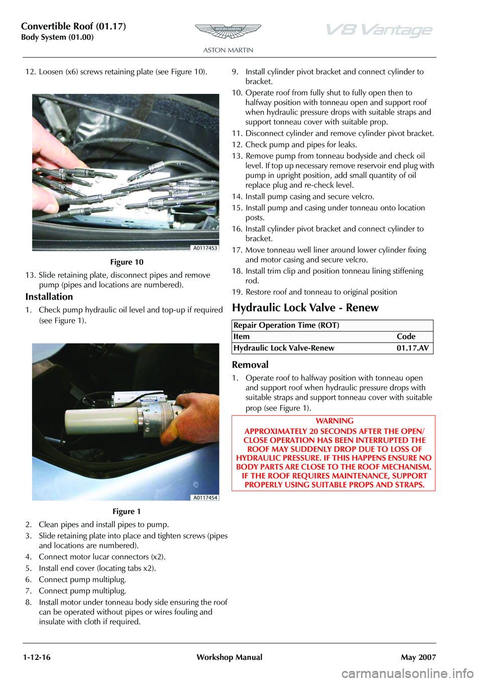
12. Loosen (x6) screws retain ing plate (see Figure 10).
13. Slide retaining plate, disconnect pipes and remove pump (pipes and locations are numbered).
Installation
1. Check pump hydraulic oil le vel and top-up if required
(see Figure 1).
2. Clean pipes and install pipes to pump.
3. Slide retaining plate into place and tighten screws (pipes and locations are numbered).
4. Connect motor lucar connectors (x2).
5. Install end cover (locating tabs x2).
6. Connect pump multiplug.
7. Connect pump multiplug.
8. Install motor under tonneau body side ensuring the roof can be operated without pipes or wires fouling and
insulate with cloth if required. 9. Install cylinder pivot bracket and connect cylinder to
bracket.
10. Operate roof from fully shut to fully open then to halfway position with tonneau open and support roof
when hydraulic pressure drop s with suitable straps and
support tonneau cover with suitable prop.
11. Disconnect cylinder and remove cylinder pivot bracket.
12. Check pump and pipes for leaks.
13. Remove pump from tonneau bodyside and check oil level. If top up necessary remove reservoir end plug with
pump in upright position, add small quantity of oil
replace plug and re-check level.
14. Install pump casing and secure velcro.
15. Install pump and casing under tonneau onto location posts.
16. Install cylinder pivot bracket and connect cylinder to bracket.
17. Move tonneau well liner arou nd lower cylinder fixing
and motor casing and secure velcro.
18. Install trim clip and positi on tonneau lining stiffening
rod.
19. Restore roof and tonneau to original positionHydraulic Lock Valve - Renew
Removal
1. Operate roof to halfway position with tonneau open and support roof when hydraulic pressure drops with
suitable straps and support tonneau cover with suitable
prop (see Figure 1).
Figure 10
Figure 1
Repair Operation Time (ROT)
ItemCode
Hydraulic Lock Valve-Renew 01.17.AV
WAR NI NG
APPROXIMATELY 20 SECONDS AFTER THE OPEN/
CLOSE OPERATION HAS BEEN INTERRUPTED THE ROOF MAY SUDDENLY DROP DUE TO LOSS OF
HYDRAULIC PRESSURE. IF THIS HAPPENS ENSURE NO
BODY PARTS ARE CLOSE TO THE ROOF MECHANISM. IF THE ROOF REQUIRES MAINTENANCE, SUPPORT
PROPERLY USING SUITABLE PROPS AND STRAPS.
Page 224 of 947
Subframes (02.03)
Frame and Mounting (02.00)
2-1-2 Workshop Manual May 2007
Frame and Mounting (02.00)
Subframes (02.03)
Specifications
Maintenance
Front Subframe-Renew
Removal
1. Switch battery isolation switch ‘OFF’.
2. Raise vehicle on ramp.
3. Remove RH wheel arch liner (see Workshop Manual procedure 01.02.GB Wheel Arch Liner - Front - RH -
Renew).
4. Remove LH wheel arch liner (see Workshop Manual procedure 01.02.FB Wheel Arch Liner - Front - LH -
Renew)
5. Remove road wheel/s.
6. Remove front spring/damper assemblies (see Workshop Manual procedure 04.03.AA Spring and Damper
Assembly - Front Pair - Renew).
7. Remove nuts (x2) from track rod ends to vertical link.
8. Using special tool 204-523, release track rod end from vertical link.
9. Disconnect ABS sensor multiplugs then release sensor harness clips (x6) from upper suspension arm and
vertical link.
10. Disconnect brake pad wear sensor multiplug then release sensor harness clips (x2) from upper suspension
arms. 11. Remove Allen bolts (x4) from brake callipers to vertical
link and tie callipers aside.
12. Remove Torx screws (x4) from brake disc to hub and remove brake disc.
13. Remove anti-roll bar links nuts (x2) and washers (x2).
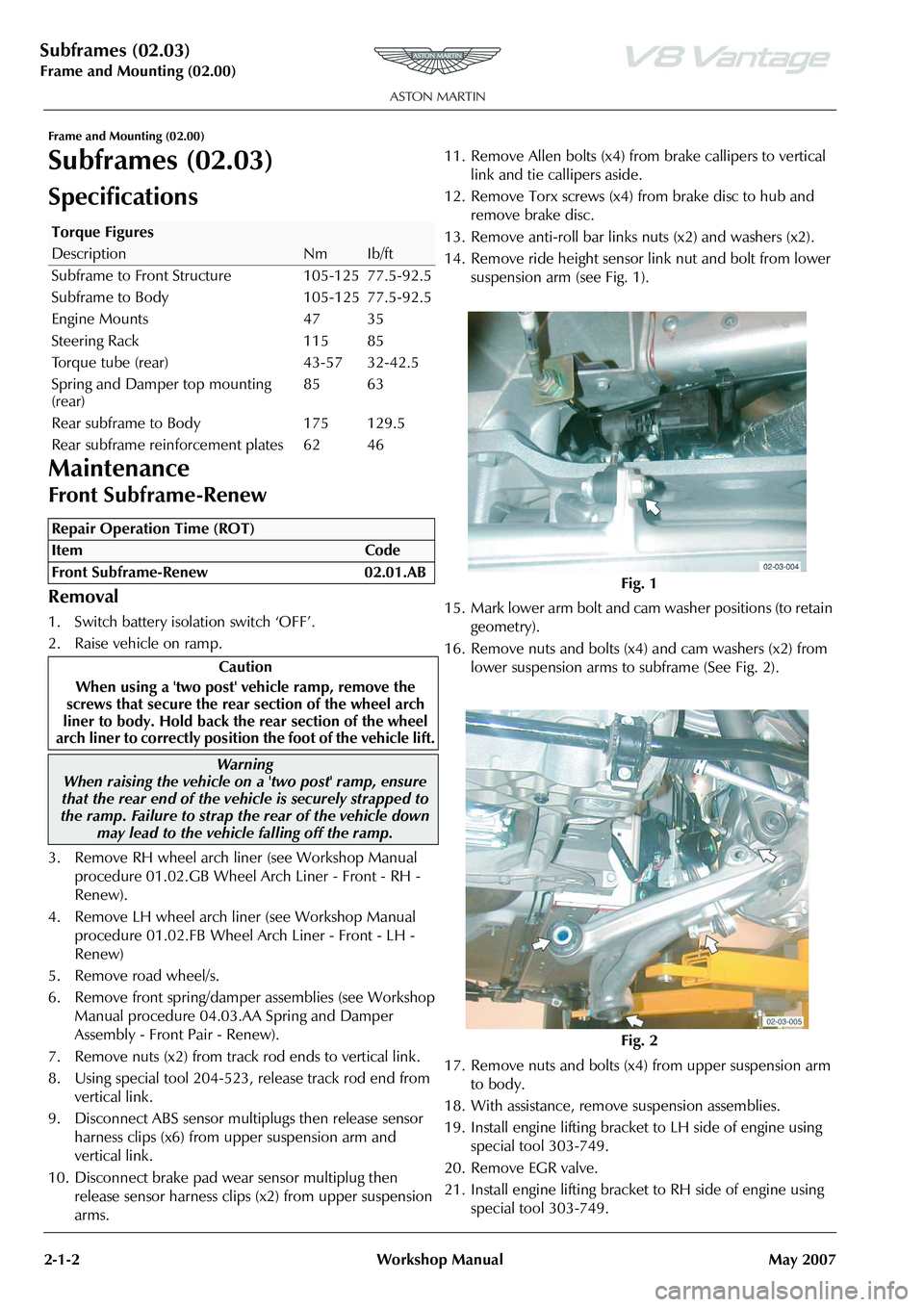
14. Remove ride height sensor link nut and bolt from lower
suspension arm (see Fig. 1).
15. Mark lower arm bolt and cam washer positions (to retain
geometry).
16. Remove nuts and bolts (x4) and cam washers (x2) from lower suspension arms to subframe (See Fig. 2).
17. Remove nuts and bolts (x4) from upper suspension arm to body.
18. With assistance, remove suspension assemblies.
19. Install engine lifting bracket to LH side of engine using special tool 303-749.
20. Remove EGR valve.
21. Install engine lifting bracket to RH side of engine using special tool 303-749.
Torque Figures
DescriptionNmIb/ft
Subframe to Front Structure 105-125 77.5-92.5
Subframe to Body 105-125 77.5-92.5
Engine Mounts 47 35
Steering Rack 115 85
Torque tube (rear) 43-57 32-42.5
Spring and Damper top mounting
(rear) 85 63
Rear subframe to Body 175 129.5
Rear subframe reinforcement plates 62 46
Repair Operation Time (ROT)
Warning
When raising the vehicle on a 'two post' ramp, ensure
that the rear end of the vehi cle is securely strapped to
the ramp. Failure to strap th e rear of the vehicle down
may lead to the vehicl e falling off the ramp.
Fig. 1
Fig. 2
Page 226 of 947
Subframes (02.03)
Frame and Mounting (02.00)
2-1-4 Workshop Manual May 2007
18. With assistance, install suspension assemblies, lower suspension arms, nuts and bolts and cam washers
(x2)(do not torque tighten at this stage).
19. Install upper suspension arms to body (do not torque tighten at this stage).
20. Install ride height sensor link to lower suspension arm and tighten.
21. Install and tighten nuts (x2) from track rod ends to vertical link.
22. Install anti-roll bar to links nuts and washers (x2) and tighten.
23. Clean and install brake discs and install and tighten Torx screws (x4)).
24. Install brake callipers and to rque tighten Allen bolts (x4).
25. Connect brake pad wear sensor multiplug and secure harness clips (x4) in upper suspension arms.
26. Connect ABS sensor multiplugs and secure harness clips (x6) in upper suspension arms and vertical links.
27. Install road wheel/s.
28. Lower vehicle on ramp.
29. Torque tighten suspension nuts and bolts.
30. Battery isolation switch ‘ON’.
31. 4 wheel alignment check and adjust (See Workshop Manual procedure 04.00.AD 4 Wheel Alignment -
Check and Adjust).
Front Subframe-Remove/Refit
Removal
1. Switch battery isolation switch ‘OFF’.
2. Raise vehicle on ramp.
3. Remove road wheel(s).
4. Remove RH wheel arch liner (See Workshop Manual procedure 01.02.GB Wheel Arch Liner - Front - RH -
Renew).
5. Remove LH wheel arch liner (See Workshop Manual procedure 01.02.FB Wheel Arch Liner - Front - LH -
Renew). 6. Remove front spring and damper assemblies (See
Workshop Manual proced ure 04.03.AA Spring &
Damper Assembly - Front Pair - Renew).
7. Remove nuts (x2) from track rod ends to vertical link.
8. Using special tool 204 - 52, release track rod end from vertical link.
9. Disconnect ABS sensor mu ltiplug and release sensor
harness clips (x6) from upper suspension arm and
vertical link.
10. Disconnect brake pad wear sensor multiplug and release sensor harness clips (x4) from upper suspension arm.
11. Remove Allen bolts (x4) from brake callipers to vertical link and tie callipers aside.
12. Remove Torx screws (x4) from brake disc to hub and remove brake disc.
13. Remove anti-roll bar links nuts (x2) and washers (x2).
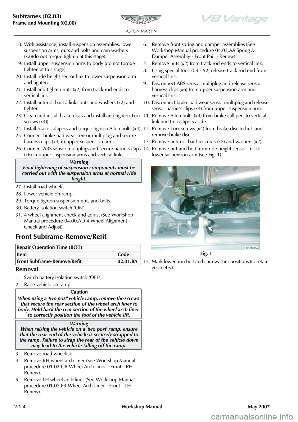
14. Remove nut and bolt from ride height sensor link to lower suspension arm (see Fig. 1).
15. Mark lower arm bolt and cam washer positions (to retain
geometry).
Warning
Final tightening of suspension components must be
carried out with the suspension arms at normal ride
height.
Repair Operation Time (ROT)
Warning
When raising the vehicle on a 'two post' ramp, ensure
that the rear end of the vehi cle is securely strapped to
the ramp. Failure to strap th e rear of the vehicle down
may lead to the vehicl e falling off the ramp.
Fig. 1
Page 228 of 947
Subframes (02.03)
Frame and Mounting (02.00)
2-1-6 Workshop Manual May 2007
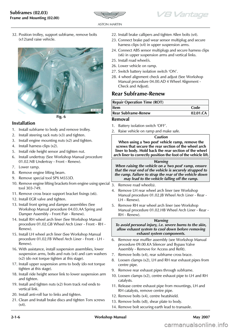
32. Position trolley, support subframe, remove bolts (x12)and raise vehicle.
Installation
1. Install subframe to body and remove trolley.
2. Install steering rack nuts (x3) and tighten.
3. Install engine mounting nuts (x2) and tighten.
4. Install harness clips (x2).
5. Install ride height sensor and tighten nut.
6. Install undertray (See Workshop Manual procedure 01.02.NB Undertray - Front - Renew).
7. Lower ramp.
8. Remove engine lifting beam.
9. Remove special tool SPX M553D.
10. Remove engine lifting bracket s from engine using special
tool 303-749.
11. Remove cross brace support bracket fixings (x6).
12. Install EGR valve and tighten.
13. Install front spring and damper assemblies (See Workshop Manual procedure 04.03.AA Spring and
Damper Assembly - Front Pair - Renew).
14. Install RH wheel arch liner (See Workshop Manual procedure 01.02.GB Wheel Arch Liner - Front - RH -
Renew).
15. Install LH wheel arch liner (See Workshop Manual procedure 01.02.FB Wheel Arch Liner - Front - LH -
Renew).
16. With assistance, install suspension assemblies, lower suspension arms, bolts and nuts (x4) and cam washers
(x2) (do not torque tighten at this stage).
17. Install upper suspension arms to body (do not torque tighten at this stage).
18. Install ride height sensor link to lower suspension arm and tighten.
19. Install and tighten nuts (x2) from track rod ends to vertical link.
20. Install anti-roll bar to links and tighten.
21. Clean and Install brake discs and tighten Torx screws (x4). 22. Install brake callipers and tighten Allen bolts (x4).
23. Connect brake pad wear se
nsor multiplug and secure
harness clips (x4) in upper suspension arms.
24. Connect ABS sensor multiplu gs and secure harness clips
(x6) in upper suspension arms and vertical links.
25. Install road wheel/s.
26. Lower vehicle on ramp.
27. Switch battery isolation switch ‘ON’.
28. 4 wheel alignment check and adjust (See Workshop Manual procedure 04.00.AD 4 Wheel Alignment -
Check and Adjust).
Rear Subframe-Renew
Removal
1. Battery isolation switch ‘OFF’.
2. Raise vehicle on ramp and make safe.
3. Remove road wheel(s).
4. Remove LH rear wheel arch liner (see Workshop Manual procedure 01.02.JB Wheel Arch Liner - Rear -
LH - Renew).
5. Remove RH rear wheel arch liner (see Workshop Manual procedure 01.02.HB Wheel Arch Liner - Rear -
RH - Renew).
6. Remove rear muffler asse mbly (see Workshop Manual
procedure 09.00.KA Silencer and Bypass Valve
Assembly - Remove for Access and Refit).
7. Remove bolts (x4), rear subframe cross brace.
8. Loosen clamps (x2), LH and RH rear exhaust pipes from
centre pipe.
9. Remove rear exhaust pipes through subframe.
10. Loosen clamps (x2), centre exhaust pipe to LH and RH
catalysts.
11. Release centre exhaust pipe from mountings, LH and RH catalysts, remove centre pipe.
12. Remove bolts (x4), centre heatshield.
13. Remove bolts (x8), shear plate to body.
14. Remove bolt securing earth lead to transaxle.
Fig. 6
Repair Operation Time (ROT)
ItemCode
Rear Subframe-Renew 02.01.CA
Caution
When using a 'two post' vehicle ramp, remove the
screws that secure the rear section of the wheel arch
liner to body. Hold back the rear section of the wheel
arch liner to correctly position the foot of the vehicle lift.
Warning
When raising the vehicle on a 'two post' ramp, ensure
that the rear end of the vehi cle is securely strapped to
the ramp. Failure to strap th e rear of the vehicle down
may lead to the vehicl e falling off the ramp.
Warning
To avoid personal injury, i.e. severe burns to the skin, allow exhaust system to cool down before removing
exhaust system components.
Page 230 of 947
Subframes (02.03)
Frame and Mounting (02.00)
2-1-8 Workshop Manual May 2007
8. Remove bolts (x2), remove both spring/damper assemblies.
9. Remove nuts (x2), anti-roll bar links to lower suspension
arms.
10. Remove bolts (x4). anti-roll bar to subframe. Remove anti-roll bar.
11. Disconnect ABS sensor mult iplugs (x2), release sensor
harness clips (x4) from both toe control arms.
12. Disconnect brake pad wear sensor multiplugs (x2). Release connectors (x2) from subframe.
13. Loosen and disconnect brake pipe unions (x2) from subframe brackets. Pl ug pipe connections.
14. Disconnect multiplug fr om ride height sensor.
15. Remove nut/bolt securing ride height sensor link to
upper suspension arm.
16. Remove bolts (x2), ride height sensor to subframe. Remove sensor.
17. Remove nuts/bolts (x2) and cam washers (x2), toe control arms to subframe.
18. Remove bolts (x2), nuts/bolts (x2) and cam washers (x2),
securing lower suspension arms to subframe
19. Remove nuts/bolts (x4), upper suspension arms to subframe.
20. With assistance, remove suspension assemblies from subframe.
21. Remove heatshield clips (x2) from rear of subframe.
22. Release clips (x23), ha rness to subframe, remove
harness.
23. Release brake pipes from cl ips (x7), remove pipes (x2).
24. Remove brake pipe clips (x5) from subframe.
Installation
1. Clean suspension components and brake pipes.
2. Instal brake pipe clips (x5) in subframe.
3. Install brake pipes (x2) in clips (x7).
4. Install harness and secure with clips (x23).
5. Install heatshield clips (x2).
6. With assistance, install suspension assemblies in subframe.
7. Install bolts/nuts (x4), upper suspension arm to subframe. Do not torque tighten at this stage.
8. Install bolts (x2), bolts/nuts (x2) and cam washers (x2) securing lower suspension arm to subframe. Do not
torque tighten at this stage.
9. Position toe control arm, install bolts (x2, cam washers (x2 and nuts (x2). Do not torque tighten at this stage.
10. Install ride height sensor, in stall and torque tighten bolts
(x2).
11. Align ride height sensor li nk to upper suspension arm,
install bolt/nut, tighten to correct torque.
12. Connect multiplug to ride height sensor. 13. Remove pipe plugs, install and torque tighten brake
pipe unions.
14. Connect brake pad wear sensor multiplugs, install in subframe brackets.
15. Connect ABS sensor multiplugs (x2), install harness clips (x4), in toe control arms.
16. Install anti-roll bar, install bolts (x4). Do not torque tighten at this stage.
17. Align anti-roll bar links to lower suspension arms. Install nuts (x2), do not torque tighten at this stage.
18. Install spring/damper assemblies (x2). Install bolts (x2), do not torque tighten at this stage
19. With assistance, install transaxle in subframe. Install and torque tighten hydramount nuts (x2).
20. Lower hoist, remove slings.
21. Align driveshafts to transaxle flanges, install plates (x6), new Allen bolts (x12) and tighten to correct torque.
22. Install rear subframe asse mbly (see Workshop Manual
procedure 02.01.CA Subframe Assembly - Rear -
Remove for Access and Refit).
23. Connect vehicle battery.
24. 4 wheel alignment check/adjust (see Workshop Manual procedure 04.00.AD 4 Wheel Alignment - Check and
Adjust).
25. Final torque tighten all suspension nuts/bolts.
RH/LH Transmission Rear Hydromount
Isolator Assembly-Renew
Removal
1. Raise vehicle on ramp.
2. Remove rear exhaust silenc er (see Workshop Manual
procedure 09.00.KA Silencer and Bypass Valve
Assembly - Remove for Access and Refit).
3. Remove bolts (x4) from subframe cross brace.
4. Loosen clamp nut and release rear exhaust pipe from centre pipe.
5. Remove rear exhaust pipe through subframe.
6. Position hydraulic lift er to support transaxle.
Caution
Always plug pipe connections to prevent ingress of dirt.
New Allen bolts should have a thread lock coating.
Caution
Final tightening of suspension components must be
carried out with the suspensi on arms at normal ride
height.
Repair Operation Time (ROT)
ItemCode
Transmission Rear Hydromount
Isolator Assembly-Renew RH
02.03.BC
Transmission Rear Hydromount
Isolator Assembly-Renew LH
02.03.BD
Warning
To avoid personal injury, i.e. severe burns to the skin, allow exhaust system to cool down before removing
exhaust system components.
Page 415 of 947
Evaporative Emissions (03.13)
Engine (03.00)
May 2007 Workshop Manual 3-13-1
Engine (03.00)
Evaporative Emissions (03.13)
Description
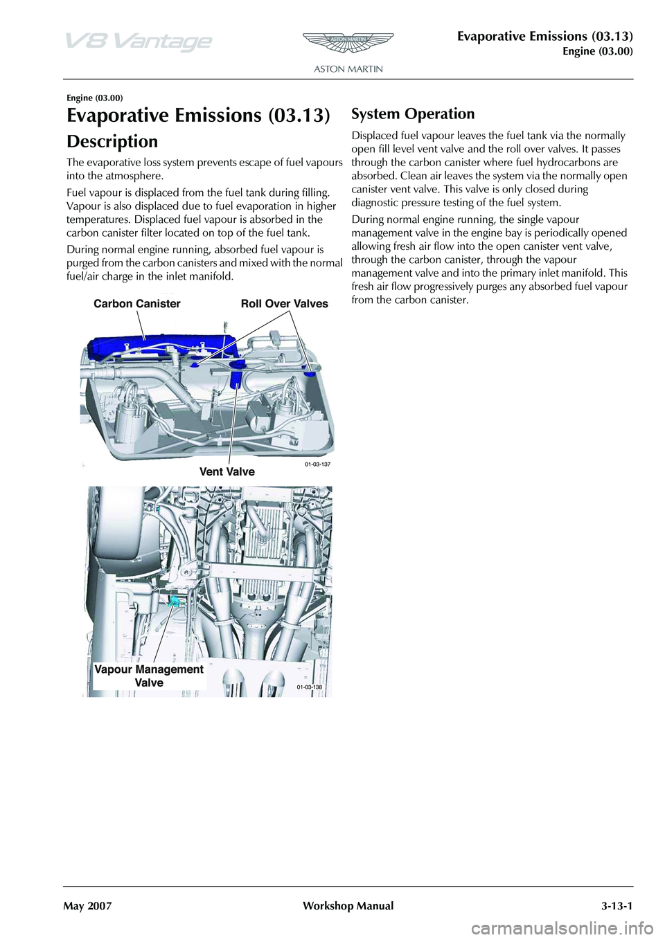
The evaporative loss system prevents escape of fuel vapours
into the atmosphere.
Fuel vapour is displaced from the fuel tank during filling.
Vapour is also displaced due to fuel evaporation in higher
temperatures. Displaced fuel vapour is absorbed in the
carbon canister filter located on top of the fuel tank.
During normal engine running, absorbed fuel vapour is
purged from the carbon canisters and mixed with the normal
fuel/air charge in the inlet manifold.
System Operation
Displaced fuel vapour leaves the fuel tank via the normally
open fill level vent valve and the roll over valves. It passes
through the carbon canister where fuel hydrocarbons are
absorbed. Clean air leaves the system via the normally open
canister vent valve. This valve is only closed during
diagnostic pressure testing of the fuel system.
During normal engine ru nning, the single vapour
management valve in the engine bay is periodically opened
allowing fresh air flow into th e open canister vent valve,
through the carbon canister, through the vapour
management valve and into the primary inlet manifold. This
fresh air flow progressively purg es any absorbed fuel vapour
from the carbon canister.
Page 425 of 947
Issue 6, May 2010 Workshop Manual 1-1-1
Suspension (04.00)
Contents
Road Wheel Alignment (04.00) ............................. 4-0-2Specifications ......................................................... 0-2
Maintenance ........................................................... 0-2All Wheel Alignment .............................................. 0-2
Front Suspension (04.01)....................................... 4-1-1 Description ............................................................. 1-1Suspension Arms .................................................... 1-1
Anti-roll Bar ........................................................... 1-1
Vertical link............................................................ 1-1
Specifications.......................................................... 1-1
Symptoms ............................................................... 1-2
Maintenance ........................................................... 1-3 RH/LH Front Hub and Bearing Assembly
- Renew ................................................................. 1-3
RH/LH Lower Front Suspension Arm Assembly
- Renew ................................................................. 1-4
RH/LH Upper Front Suspension Arm Assembly
- Renew ................................................................. 1-4
Front Anti-Roll Bar - Renew ................................... 1-5
Front Pair Anti-Roll Bar Bushing - Renew................ 1-5
RH/LH Front Anti-Roll Bar Link - Renew ................ 1-5
RH/LH Front Hub Vertical Link - Renew ................ 1-6
Front Suspension Sensor Assembly-Renew ............. 1-7
Rear Suspension (04.02) ........................................ 4-2-1 Description ............................................................. 2-1Suspension Arms .................................................... 2-1
Anti-roll Bar ........................................................... 2-1
Vertical Link........................................................... 2-1
Specifications.......................................................... 2-2
Maintenance ........................................................... 2-2 RH/LH Rear Hub and Bearin g Assembly-Renew ..... 2-2
RH/LH Rear Lower Arm Assembly-Renew .............. 2-2
RH/LH Upper Rear Arm Assembly-Renew .............. 2-3
RH/LH Toe Control Rear Arm Assembly-Renew ..... 2-3
Rear Anti-Roll Bar-Renew ...................................... 2-3
Rear Pair-Anti-Roll Bar Bushing-Renew .................. 2-4
RH/LH Rear Anti-Roll Bar Link-Renew ................... 2-4
RH/LH Rear Hub Vertical Link-Renew.................... 2-4
Rear Suspension Sensor Assembly-Renew .............. 2-5
Shock Absorber System (04.03) ............................. 4-3-1 Description ............................................................. 3-1
Specifications.......................................................... 3-1
Maintenance ........................................................... 3-1Front Spring and Damper Assembly-Pair-Renew .... 3-1
Front Spring-Pair-Renew ........................................ 3-3
Front Damper-Pair-Renew ..................................... 3-4
Rear Spring and Damper Assembly-Pair-Renew...... 3-5
Rear Spring-Pair-Renew ......................................... 3-7
Rear Damper-Pair-Renew ...................................... 3-9
Road Wheels and Tyres (04.04)............................. 4-4-1 Specifications.......................................................... 4-1USA Tyre Gradings................................................. 4-2
Tread Wear ........................................................... 4-2
Traction ................................................................. 4-2 Temperature .......................................................... 4-2
Maintenance ........................................................... 4-3 Safety .................................................................... 4-3
Tyre Replacement and Wheel Interchanging ......... 4-3
Winter (Snow) tyres ................................................ 4-4 Recommended Winter Wheel and
Tyre Combination .................................................. 4-4
Inspection and Verification . ................................... 4-4
Tyre Wear ............................................................. 4-4
Tyre Damage ......................................................... 4-6
Repairs .................................................................. 4-7
Care of Alloy Road Wheels .................................... 4-7
Road Wheel Alignment .......................................... 4-7
Road Wheel and Tyre Balance ............................... 4-8
Torque Tightening of Road Wheel Nuts ................ 4-8
Tyre Pressure Sensing (Option).............................. 4-9 Pressure Sensing with Wint er Wheels and Tyres ..... 4-9
Warnings ............................................................... 4-9
Display Unit ........................................................ 4-10
System Programming ........................................... 4-10
Page 427 of 947

Front Suspension (04.01)
Suspension (04.00)
November 2008 Workshop Manual 4-1-1
Suspension (04.00)
Front Suspension (04.01)
Description
Suspension Arms
The upper suspension arm is attached to the body structure.
The lower suspension arm is attached to the front subframe.
Each upper suspension arm has a press-fit ball-joint, and two
interleaved rubber bushes. Two bolts attach the upper
suspension arm to the body structure.
Each lower suspension arm has a press fit ball-joint and
metal-to-rubber bonded bushes which are attached to the
front subframe by two eccentric cam bolts (Camber and
castor settings).
Anti-roll Bar
The anti-roll bar, is attached to the subframe in two positions
by rubber bushes and clamps. The outer ends of the anti-roll
bar are attached to the lower suspension arms by drop links.
The anti-roll bar provides the required stiffness to control
body roll.
Vertical link
The Vertical link (Knuckle Joint) swivels on the upper and
lower suspension arms via ball-joints, and carries the hub, a
unit 3 wheel bearing (including the ABS encoder ring), the
wheel speed sensor, the brake caliper, and the brake disc
and shield. The position of the Vertical link is determined by
the movement of the steering rack, which is connected to
the Vertical link by the steering track rod.
Specifications
Upper Arm Ball Joint
and Bushes
Ball Joint
and Bushes Verticle
Link
Bolts to Body
Lower Arm
Anti-roll Bar Drop Links
Eccentric
Cam Bolts
04-01-003
Torque Figures
DescriptionNmlb. / ft.
Brake dust shield. 9 7
Bearing Assembly to the Vertical
link. 55 41
Vertical Link to the Lower
Suspension Arm. 90 66.5
Vertical Link to the Upper
Suspension Arm. 90 66.5
Track-rod End Lock Nut. 70 52
Vehicle Ride Height Sensor. M8 M522.5
9 17
7
Anti-roll Bar Link Nuts 110 81.5
Anti-roll Bar Mounting Bolts
Torque bolt 1, then bolt 2, then
bolt 1 again (to allow for rubber
compression) 22.5 17
Torque the following suspensi on fixings with the vehicle
at normal ride height
Lower Suspension Arm front
bush to the Subframe M14 185 137
Lower Suspension Arm rear
bush to the Subframe. M12 115 85
Upper Suspension Arm to the
Front Structure 115 85
Spring and Damper Bolts Top Lower22.5
175 17
129.5
Normal ride height 2 x 37.5kg in front seats (37.5kg in
each seat) plus a full fuel tank.