CD player ASTON MARTIN V8 VANTAGE 2010 Workshop Manual
[x] Cancel search | Manufacturer: ASTON MARTIN, Model Year: 2010, Model line: V8 VANTAGE, Model: ASTON MARTIN V8 VANTAGE 2010Pages: 947, PDF Size: 43.21 MB
Page 692 of 947

Wiring and Circuit Protection (18.01)
Electric Distribution/Electronic Control (18.00)
May 2007 Workshop Manual 18-1-3
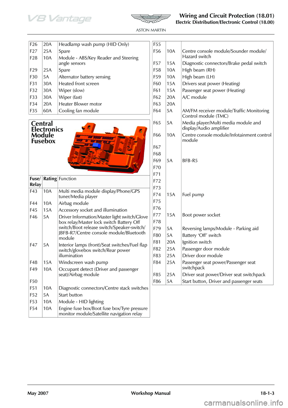
F26 20A Headlamp wash pump (HID Only)
F27 25A Spare
F28 10A Module - ABS/Key Reader and Steering angle sensors
F29 25A Spare
F30 5A Alternator battery sensing
F31 30A Heated front screen
F32 30A Wiper (slow)
F33 30A Wiper (fast)
F34 20A Heater Blower motor
F35 60A Cooling fan module
Central
Electronics
Module
Fusebox
Fuse/
RelayRatingFunction
F43 10A Multi media module display/Phone/GPS tuner/Media player
F44 10A Airbag module
F45 15A Accessory socket and illumination
F46 5A Driver Information/Master light switch/Glove box relay/Master lock switch Battery Off
switch/Boot release switch/Speaker-switch/
JBFB-R7/Centre console module/Bluetooth
module
F47 5A Interior lamps (front)/Seat switches/Fuel flap switch/glovebox switch/Rear power
illumination
F48 15A Windscreen wash pump
F49 10A Occupant detect (Driver and passenger seat)/Airbag module
F50
F51 10A Diagnostic connectors/Centre stack switches
F52 5A Start button
F53 10A Module - HID lighting
F54 10A Engine fuse box/Boot fuse box/Tyre pressure monitor module/Satellite navigation relay
F55
F56 10A Centre console module/Sounder module/
Hazard switch
F57 15A Diagnostic connectors/Brake pedal switch
F58 10A High beam (RH)
F59 10A High beam (LH)
F60 15A Drivers seat power (Heating)
F61 15A Passenger seat power (Heating)
F62 20A A/C module
F63 20A
F64 5A AM/FM receiver module/Traffic Monitoring Control module (TMC)
F65 5A Media player/Multi media module and display/Audio amplifier
F66 10A Centre console module/Infotainment control module
F67
F68
F69 5A BFB-R5
F70
F71
F72
F73
F74 15A Fuel pump
F75
F76
F77 15A Boot power socket
F78
F79 5A Reversing lamps/Module - Parking aid
F80 5A Battery ‘Off’ switch
F81 20A Ignition switch
F82 25A Passenger door module
F83 25A Driver door module
F84 25A Passenger seat power/Passenger seat switchpack
F85 25A Driver seat power/Driver seat switchpack
F86 5A Start button, Driver and passenger seats
Page 715 of 947

Wiring and Circuit Protection (18.01)
Electric Distribution/E lectronic Control (18.00)
18-1-26 Workshop Manual May 2007
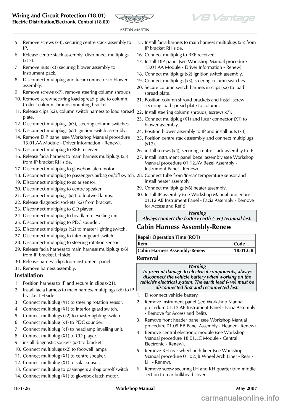
5. Remove screws (x4), securing centre stack assembly to
IP.
6. Release centre stack assembly, disconnect multiplugs (x12).
7. Remove nuts (x3) securing blower assembly to instrument pack.
8. Disconnect multiplug and lucar connector to blower assembly.
9. Remove screws (x7), remove steering column shrouds.
10. Remove screw securing load spread plate to column. Collect column shrouds mounting bracket.
11. Release clips (x2), column switch harness to load spread plate.
12. Disconnect multiplugs (x3), steering column switches.
13. Disconnect multiplugs (x2) ignition switch assembly.
14. Remove DIP panel (see Workshop Manual procedure 13.01.AA Module - Driver Information - Renew).
15. Disconnect multiplug to RKE receiver.
16. Release facia harness to main harness multiplugs (x5) from IP bracket RH side.
17. Disconnect multiplug to glovebox latch motor.
18. Disconnect multiplug to pass engers airbag on/off switch.
19. Disconnect multiplug to solar sensor.
20. Disconnect multiplug to centre speaker.
21. Disconnect multiplugs (x2) to footwell lamps.
22. Release diagnostic sockets (x2) from bracket.
23. Disconnect multiplug to CD player.
24. Disconnect multiplug to headlamp levelling unit.
25. Disconnect multiplug to PDC sounder.
26. Disconnect multiplugs (x2) to master lighting switch.
27. Disconnect multiplug to interior guard switch.
28. Disconnect multiplug to steering rotation sensor.
29. Release facia harness to main harness multiplugs (x6) from IP bracket LH side.
30. Release harness clips from instrument panel.
31. Remove harness assembly.
Installation
1. Position harness to IP and secure in clips (x21).
2. Install facia harness to main harness multiplugs (x6) to IP bracket LH side.
3. Connect multiplug (X1) to steering rotation sensor.
4. Connect multiplug (X1) to interior guard switch.
5. Connect multiplugs (x2) to master lighting switch.
6. Connect multiplug (x1) to PDC sounder.
7. Connect multiplug (x1) to headlamp levelling unit.
8. Connect multiplug (X1) to CD player.
9. install diagnostic sockets (x2) to bracket.
10. Connect multiplugs (x2) to footwell lamps.
11. Connect multiplug (X1) to centre speaker.
12. Connect multiplug (X1) to solar sensor.
13. Connect multiplug to passengers airbag on/off switch.
14. Connect multiplug (X1) to glovebox latch motor. 15. Install facia harness to main harness multiplugs (x5) from
IP bracket RH side.
16. Connect multiplug to RKE receiver.
17. Install DIP panel (see Workshop Manual procedure 13.01.AA Module - Driver Information - Renew).
18. Connect multiplugs (x2) ignition switch assembly.
19. Connect multiplugs (x3), steering column switches.
20. Secure column switch harness in clips (x2) to load spread plate.
21. Position column shroud brackets and Install screw securing load spread plate to column.
22. Install steering column shrouds, (screws x7).
23. Connect multiplug (X1) an d lucar connector (X1) to
blower assembly.
24. Position blower assembly to IP and install nuts (x3)
25. Position centre stack assembly and connect multiplugs (x12).
26. install screws (x4), securing centre stack assembly to IP.
27. Install instrument panel bezel assembly (see Workshop Manual procedure 01.12.AV Bezel Assembly -
Instrument Panel - Renew).
28. Connect tube from 'In-car' temperature sensor and install heater assembly.
29. Connect multiplugs (x6) heater assembly.
30. Install IP assembly (see Workshop Manual procedure
01.12.AB Instrument Panel - Facia Assembly - Remove
for Access and Refit).
Cabin Harness Assembly-Renew
Removal
1. Disconnect vehicle battery.
2. Remove instrument panel (see Workshop Manual procedure 01.12.AB Instrume nt Panel - Facia Assembly
- Remove for Access and Refit).
3. Remove front header panel (see Workshop Manual procedure 01.05.BB Panel Assembly - Header - Renew).
4. Remove central electronic module (see Workshop Manual procedure 18.01.LC Module - Central
Electronic - Renew).
5. Remove RH rear wheel arch liner (see Workshop Manual procedure 01.02.JB Wheel Arch Liner - Rear -
LH - Renew).
6. Remove screw securing LH and RH quarter trim middle section to rear bulkhead cover.
Warning
Always connect the battery earth (- ve) terminal last.
Repair Operation Time (ROT)
ItemCode
Cabin Harness Assembly-Renew 18.01.GB
Warning
To prevent damage to elec trical components, always
disconnect the vehicle battery when working on the
vehicle's electrical system. The earth lead (- ve) must be
disconnected first and reconnected last.
Page 812 of 947

Electronics Training Programme
INTRODUCTION
The Bluetooth system offers the following features:
• Seamless, wireless handsfree audio through a Bluetooth connection
• Digital audio interface with high qu ality, full-duplex, handsfree speech
• Speaker Independent Voice Recognition (VR)
• Voice-driven menu prompts
• Automatically mutes the radio
• Automatically pauses the CD player during calls
• Noise reduction and acoustic echo cancellation
• Compliance with Bluetooth Ha nds Free 0.96 and 1.0 profiles
• Audio through the door speakers
The Bluetooth system is standard fitment on DB9 an d is optional on the V8 Vantage. The control and
operation of the Bluetooth system is identical on a ll models, however the electrical architecture of the
cars audio does differ. To identify if Bluetooth is fitted, look for the LED Indicator located as shown
below:
LED Indicator
7