ading oil ASTON MARTIN V8 VANTAGE 2010 Workshop Manual
[x] Cancel search | Manufacturer: ASTON MARTIN, Model Year: 2010, Model line: V8 VANTAGE, Model: ASTON MARTIN V8 VANTAGE 2010Pages: 947, PDF Size: 43.21 MB
Page 8 of 947
Safety Precautions
0-0-8 Workshop Manual Issue 5, January 2010
Tools and Equipment
• Do not leave tools, equipment, spilt oil, etc. around or on the work area.
• Ensure that tools and equipment used are in good condition; do not use damaged or defective tools or
equipment.
• Do not apply heat in an attempt to free stiff nuts or fittings; as well as causing damage to protective coatings, the stray
heat may damage electronic equipment, harnesses and
brake lines.
• Use the recommended service tool where instructed to do so.
Used Engine Oil
Prolonged and repeated contact with mineral oil will result
in the removal of natural fats from the skin, leading to
dryness, irritation and dermatitis. In addition, used engine
oil contains potentially harmful contaminants which may
cause skin cancer. Adequate means of skin protection and
washing facilities should be provided.
Health protection precautions
• Avoid prolonged and repeated contact with oils, particularly used engine oil.
• Wear protective clothing , including impervious gloves where practicable.
• Do not put oily rags in pockets.
• Avoid contaminating clothes with oil.
• Overalls must be cleaned regularly. Discard un-washable clothes and oil impregnated footwear.
• First aid treatment should be obtained immediately for open cuts or wounds.
• Use barrier creams, apply before each work period to help the removal of oil from the skin.
• Wash with soap and water to ensure all oil is removed. Preparations containing lanolin replace the natural skin
oils which have been removed.
• Do not use petrol, kerosene, diesel fuel, gas oil, thinners or solvents for washing skin.
• If skin disorders develop, obtain medical advice.
• Where practicable, degrease components prior to handling .
• Where there is a risk of eye contact, eye protection should
be worn. In addition, an ey e wash facility should be
provided.
Environmental Protection
It is illegal to pour used oil on the ground, down sewers or
drains, or into water courses. The burning of used engine oil
in small space heaters or boilers is not recommended unless
emission control equipment is in stalled; in case of doubt,
contact the Local Authority for ad vice on disposal facilities.
Page 374 of 947
Power Conversion (03.11)
Engine (03.00)3-11-2 Workshop Manual May 2007
7. Release flywheel from dowel, remove flywheel.
8 . R e m o v e e n g i n e s u m p ( s e e Wo r k s h o p M a n u a l p ro c e d u r e
03.02.CN Pan - Oil Sump - Remove and re-seal With
Engine Removed).
9. Remove bolts (x8) securing windage tray to engine bedplate, remove windage tray.
10. Mark bearing caps and connecting rods for correct installation (see Figure 1).
Figure 1
11. Rotate crankshaft clockwise to access number 1 cylinder
connecting rod bolts.
12. Remove and discard bolts (x16) securing bearing caps to connecting rods, remove bearing caps (see Figure 2).
Figure 2
13. Install special tools (303-535) to the connecting rod to prevent damage to crankshaft journal.
14. Carefully push each connecting rod/piston assembly up each cylinder bore.
15. Secure Dial Test Indicator (DTI) on engine bedplate.
16. Push crankshaft fully rearwards. 17. Position DTI probe on cran
kshaft web and zero gauge.
18. Push crankshaft fully forw ards and record reading on
dial gauge.
19. Remove DTI gauge.
20. Noting their fitted positions, remove bolts (x34) securing engine bedplate to cylinder block (see Figure 3).
Figure 3
21. Carefully release and remove engine bedplate from cylinder block (see Figure 4).
Figure 4
22. Carefully remove crankshaft from cylinder block.
23. Remove rear oil seal from crankshaft.
WAR NI NG
DO NOT GET USED ENGINE OIL ON YOUR SKIN.
USED ENGINE OIL CAN BE HARMFUL.
Caution
Connecting rod bolts are tor que tightened to yield and
must be replaced.
A0311329
A0311314
A0311329
A0311329
Page 377 of 947
Power Conversion (03.11)
Engine (03.00)
May 2007 Workshop Manual 3-11-5
9. Remove bolts (x8) securing windage tray to engine
bedplate, remove windage tray.
10. Mark bearing caps and connecting rods for correct installation (see Figure 1).
Figure 1
11. Rotate crankshaft clockwis e to access number 1 cylinder
connecting rod bolts.
Remove bolts (x16) securing bearing caps to connecting rods, remove bearing caps (see Figure 2).
Figure 2
12. Install special tools (303-535) to the connecting rod to
prevent damage to crankshaft journal.
13. Carefully push each connecting rod/piston assembly up each cylinder bore.
14. Secure Dial Test Indicator (DTI) on engine bedplate.
15. Push crankshaft fully rearwards.
16. Position DTI probe on crankshaft web and zero gauge.
17. Push crankshaft fully forw ards and record reading on
dial gauge. 18. Remove DTI gauge.
19. Noting their fitted positions, remove bolts (x34) securing
engine bedplate to cylinder block (see Figure 3).
Figure 3
20. Carefully release and remove engine bedplate from cylinder block.
21. Carefully remove crankshaft from cylinder block.
22. Remove rear oil seal from crankshaft.
23. Note fitted position and remove crankshaft thrust washers (x2) from cylinder block (see Figure 4).
Figure 4
Caution
Pistons, connecting rods an d connecting rod bearings
should be numbered to make sure they are reassembled
in the same position.
Caution
Connecting rod bolts are tor q
u
e tightened to yield and
mu st be replaced.
A0311329
A0311314
A0311329
A0311334
Page 615 of 947
Power Steering (11.02)
Steering (11.00)11-2-12 Workshop Manual Issue 5, January 2010
Removal
1. Remove PAS fluid from reservoir (syringe).
2. Remove throttle body duct for access. (clips x3).
3. Remove top bolts (x2) from engine oil tank and loosen
bottom bolts (x2) (allows ta nk to move to access pipe
support fixings).
4. Remove bolts (x2) securing pipe to body.
5. Disconnect sensor multiplug.
6. Remove hose from pump union.
7. Remove pipes from steering rack (bolt x1).
8. Remove pipe from vehicle.
Installation
1. Renew o-rings on PAS pipes and pump pipe.
2. Install hose to vehicle.
3. Install bolts brackets to body.
4. Install PAS pipes to rack (bolt x1).
5. Connect sensor multiplug.
6. Install pipe to pump union.
7. Install bolts and tighten oil tank fixings (torque).
8. Install throttle body duct. (clips x3).
9. Bleed PAS system (see Workshop Manual procedure 11.01.AA Power Assisted Steering System - Bleed).
Power Steering Rack to Cooler Hose-
Renew
Removal
1. Remove radiator grille (see Workshop Manual
procedure 01.08.AA Grille - Radiator - Renew).
2. Remove PAS fluid from reservoir (syringe). 3. Remove hose from cooler (clip x1) and support clips
(x2).
4. Remove undertray (see Workshop Manual procedure 01.02.NB Undertray - Front - Renew).
5. Remove bolt, bracket to lower radiator crossmember.
6. Lower ramp.
7. Remove throttle body duct for access. (clips x3).
8. Remove pipes from st eering rack (bolt x1).
9. Remove hose from vehicle (support clips x2).
Installation
1. Renew the O-rings on the PAS pipes.
2. Install hose to vehicle (support clips).
3. Install PAS pipes to rack (bolt x1).
4. Install throttle body duct. (clips x3).
5. Raise ramp.
6. Install support clip bolt to radiator crossmember.
7. Install hose to cooler and support clips (x2).
8. Install undertray (see Workshop Manual procedure 01.02.NB Undertray - Front - Renew).
9. Install radiator grille (see Workshop Manual procedure 01.08.AA Grille - Ra diator - Renew).
10. Top up PAS fluid.
WAR NI NG
AVOID EXCESSIVE SKIN CONTACT WITH MINERAL
OIL. MINERAL OILS REMOVE THE NATURAL FATS
FROM THE SKIN, LEADING TO DRYNESS, IRRITATION AND DERMATITIS.
Caution
Always plug pipes and hoses to prevent ingress of dirt or
moisture into the system.
Repair Operation Time (ROT)
Caution
Always plug pipes and hoses to prevent ingress of dirt or moisture into the system.
Page 645 of 947
Air Conditioning (A/C) System (12.03)
Climate Control (12.00)
12-3-12 Workshop Manual May 2007
Leaks
Faults associated with low refrigerant charge weight and low pressure may be caused by leakage. Leaks traced to
mechanical connections may be caused by torque relaxation or joint face contamination. Evidence of oil around such
areas is an indicator of leakage.
Leak Detection
Fluorescent Tracer Dye - A fluorescent tracer dye is incorporated into th e refrigeration system and can be checked for
non-apparent leaks by scanning with a high intensity ultraviolet lamp. The location of leaks can be pinpointed by the bright
yellow glow of the tracer dye.
Automatic Refrigerant Leak Detector - (various manufacturers) Hand-held, portable, battery operated leak detector.
Place in and around A/C system to detect refrigerant leaks.
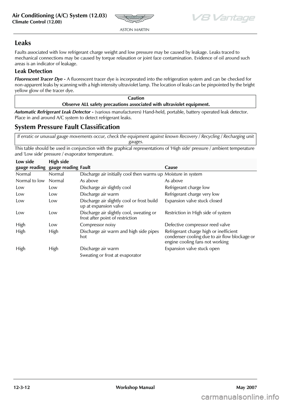
System Pressure Fault Classification
This table should be used in conjunction with the graphical representations of 'High side' pressure / ambient temperature
and 'Low side' pressure / evaporator temperature. Caution
Observe ALL safety precautions associ ated with ultraviolet equipment.
If erratic or unusual gauge movements occur, check the equipment against known Recovery / Recycling / Recharging unit
gauges.
Low side
gauge readingHigh side
gauge reading
Fault
Cause
Normal Normal Discharge air initially c ool then warms up Moisture in system
Normal to low Normal As above As above
Low Low Discharge air slightly cool Refrigerant charge low
Low Low Discharge air warm Refrigerant charge very low
Low Low Discharge air slightly cool or frost build up at expansion valve Expansion valve stuck closed
Low Low Discharge air slightly cool, sweating or frost after point of restriction Restriction in High side of system
High Low Compressor noisy Defective compressor reed valve
High High Discharge air warm and high side pipes hot Refrigerant charge high or inefficient
condenser cooling due to air flow blockage or
engine cooling fans not working
High High Discharge air warm
Sweating or frost at evaporator Expansion valve stuck open
Page 900 of 947
Aston Martin V8 Vantage 2009 MY EOBD DocumentationAston Martin/Ford Confidential
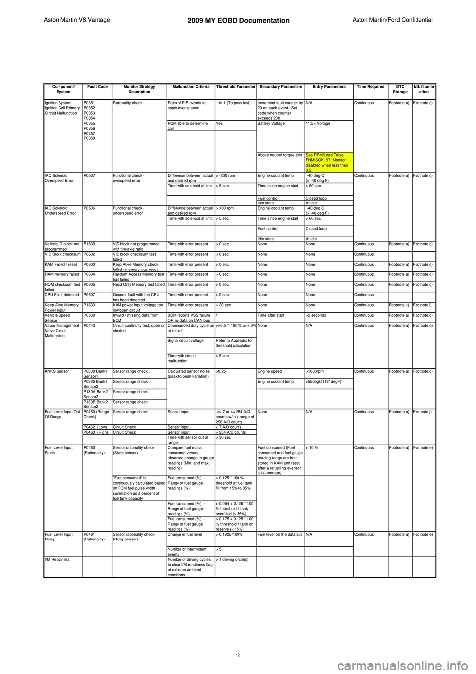
Component/ System Fault Code Monitor Strategy
Description Malfunction Criteria Threshold Parameter Secondary Parameters Entry Parameters Time Required DTC
StorageMIL Illumin-
ation
Ratio of PIP events to
spark events seen 1 to 1 (To pass test) Increment fault counter by
20 on each event. Set
code when counter
exceeds 200 N/A
PCM able to determine
coil Yes
Above neutral torque axis See RPM/Load Table FNMISOK_97: Monitor
disabled when less than
0.5
Difference between actual
and desired rpm > -200 rpm
Engine coolant temp -40 deg C
(> -40 deg F)
Time with solenoid at limit > 5 sec Time since engine start > 60 sec
Fuel control Closed loop
Idle state At idle
Difference between actual
and desired rpm > 100 rpm
Engine coolant temp -40 deg C
(> -40 deg F)
Time with solenoid at limit > 5 sec Time since engine start > 60 sec
Fuel control Closed loop
Idle state At idle
Vehicle ID block not
programmed P1639 VID block not programmed
with tire/axle ratio Time with error present > 0 sec
NoneNoneContinuous Footnote a) Footnote c)
VID Block checksum P0602 VID block checksum test failedTime with error present > 0 sec
NoneNoneContinuous
KAM Failed / reset P0603 Keep Alive Memory check failed / memory was resetTime with error present > 0 sec
NoneNoneContinuous Footnote a) Footnote c)
RAM memory failed P0604 Random Access Memory test has failed.Time with error present > 0 sec
NoneNoneContinuous Footnote a) Footnote c)
ROM checksum test
failed P0605 Read Only Memory test failed Time with error present > 0 sec
NoneNoneContinuous Footnote a) Footnote c)
CPU Fault detected P0607 General fault with the CPU has been detectedTime with error present > 0 sec
NoneNoneContinuous
Keep Alive Memory
Power Input P1633 KAM power input voltage too
low/open circuit Time with error present > 20 sec
NoneNoneContinuous Footnote k) Footnote i)
Vehicle Speed
Sensor P0500 Invalid / missing data from
BCM BCM reports VSS failure
OR no data on CAN bus1
Time after start >2 secondsContinuous Footnote a) Footnote c)
Commanded duty cycle on
or full-off >=0.5 * 100 % or = 0%
Signal circuit voltage Refer to Appendix for threshold calculation
Time with circuit
malfunction > 5 sec
P0330 Bank1
Sensor1 Sensor range check
Engine speed>1000rpm
P0325 Bank1
Sensor2 Sensor range check
Engine coolant temp >55degC (131degF)
P130A Bank2
Sensor2 Sensor range check
P130B Bank2
Sensor2 Sensor range check
P0460 (Range
Check) Sensor range check
Sensor input <= 7 or >= 254 A/D
counts w/in a range of
256 A/D counts
P0462 (Low) Circuit Check Sensor input< 7 A/D counts
P0463 (High) Circuit Check Sensor input> 254 A/D counts
Time with sensor out of
range > 30 sec
Sensor rationality check
(Stuck sensor) Compare fuel mass
consumed versus
observed change in gauge
readings (Min. and max.
reading) Fuel consumed (Fuel
consumed and fuel gauge
reading range are both
stored in KAM and reset
after a refuelling event or
DTC storage)> 10 %
"Fuel consumed" is
continuously calculated based
on PCM fuel pulse width
summation as a percent of
fuel tank capacity Fuel consumed (%) -
Range of fuel gauge
readings (%)
> 0.125 * 100 %
threshold at fuel tank
fill from 15% to 85%
Fuel consumed (%) -
Range of fuel gauge
readings (%) > 0.054 + 0.125 * 100
% threshold if tank
overfilled (> 85%)
Fuel consumed (%) -
Range of fuel gauge
readings (%) > 0.175 + 0.125 * 100
% threshold if tank on
reserve (< 15%)
Change in fuel level > 0.1925*100% Fuel level on the data bus N/A
Number of intermittent
events > 5
I/M Readiness Number of driving cycles
to clear I/M readiness flag
at extreme ambient
conditions > 1 driving cycle(s) Footnote e)
Footnote a)
Footnote c)
Footnote a) Footnote j) Footnote e)
Fuel Level Input
Noisy Continuous Footnote a)
Continuous Footnote a)
P0461
(Rationality) Sensor rationality check
(Noisy sensor)
Fuel Level Input
Stuck
P0460
(Rationality) Continuous
N/A Continuous
Calculated sensor noise
(peak to peak variation)
>0.25
KNKS Sensor
Fuel Level Input Out
Of Range NoneFootnote a) Footnote e)
Vapor Management
Valve Circuit
Malfunction P0443 Circuit continuity test, open or
shorted None
N/A Continuous
11.5< Voltage
Ignition System-
Ignition Coil Primary
Circuit Malfunction
IAC Solenoid
Underspeed Error P0507
P0506
Functional check -
overspeed error
Functional check -
underspeed error
IAC Solenoid
Overspeed Error
Footnote a) Footnote c)
Continuous
P0351
P0352
P0353
P0354
P0355
P0356
P0357
P0358
Rationality check
Continuous Footnote a) Footnote c)
Battery Voltage
12