remote control ASTON MARTIN V8 VANTAGE 2010 Workshop Manual
[x] Cancel search | Manufacturer: ASTON MARTIN, Model Year: 2010, Model line: V8 VANTAGE, Model: ASTON MARTIN V8 VANTAGE 2010Pages: 947, PDF Size: 43.21 MB
Page 121 of 947

Handles and Lock Mechanisms (01.14)
Body System (01.00)
May 2007 Workshop Manual 1-10-1
Body System (01.00)
Handles and Lock Mechanisms (01.14)
Description
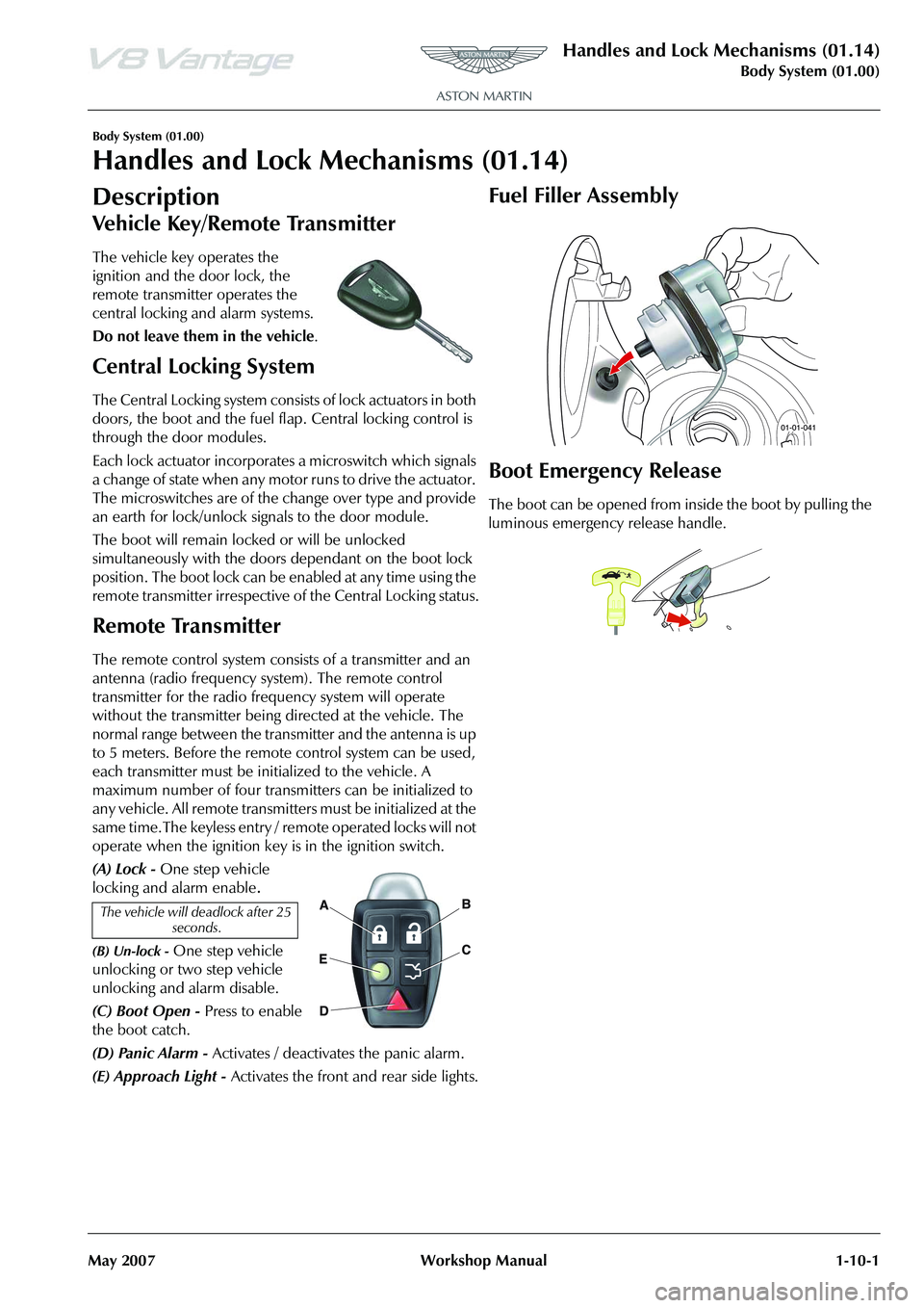
The vehicle key operates the
ignition and the door lock, the
remote transmitter operates the
central locking and alarm systems.
Do not leave them in the vehicle .
Central Locking System
The Central Locking system consists of lock actuators in both
doors, the boot and the fuel flap. Central locking control is
through the door modules.
Each lock actuator incorporates a microswitch which signals
a change of state when any motor runs to drive the actuator.
The microswitches are of the change over type and provide
an earth for lock/unlock signals to the door module.
The boot will remain locked or will be unlocked
simultaneously with the doors dependant on the boot lock
position. The boot lock can be enabled at any time using the
remote transmitter irrespective of the Central Locking status.
Remote Transmitter
The remote control system consists of a transmitter and an
antenna (radio frequency system). The remote control
transmitter for the radio frequency system will operate
without the transmitter being directed at the vehicle. The
normal range between the transmitter and the antenna is up
to 5 meters. Before the remote control system can be used,
each transmitter must be initialized to the vehicle. A
maximum number of four transmitters can be initialized to
any vehicle. All remote transmitters must be initialized at the
same time.The keyless entry / remote operated locks will not
operate when the ignition key is in the ignition switch.
(A) Lock - One step vehicle
locking and alarm enable
.
(B) Un-lock - One step vehicle
unlocking or two step vehicle
unlocking and alarm disable.
(C) Boot Open - Press to enable
the boot catch.
(D) Panic Alarm - Activates / deactivates the panic alarm.
(E) Approach Light - Activates the front and rear side lights.
Fuel Filler Assembly
Boot Emergency Release
The boot can be opened from in side the boot by pulling the
luminous emergency release handle.
The vehicle will deadlock after 25 seconds.
Page 731 of 947

Vehicle Control System (18.08)
Electric Distribution/Electronic Control (18.00)
18-2-2 Workshop Manual May 2007
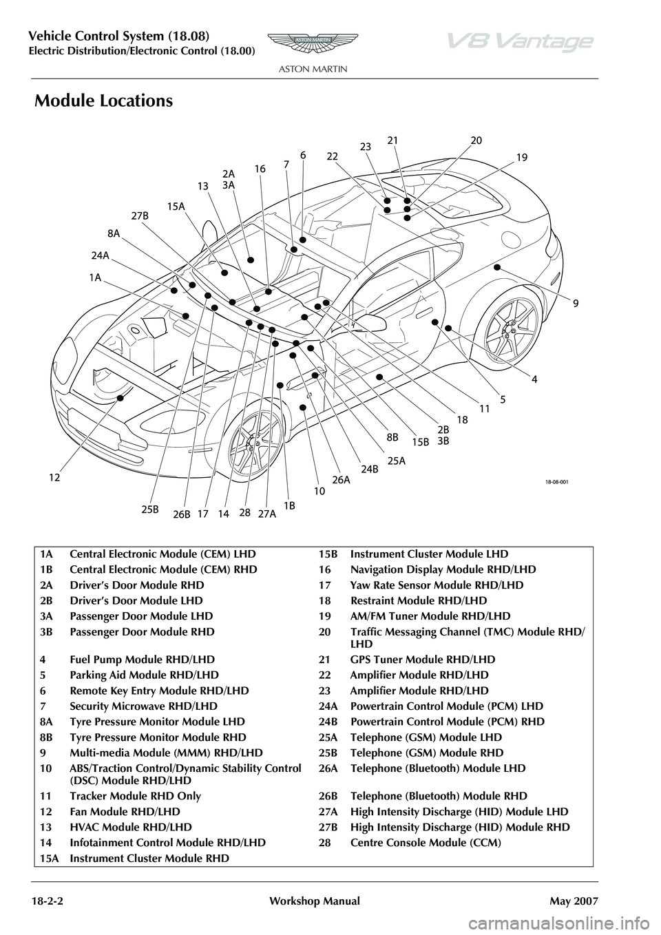
Module Locations
1A Central Electronic Module (CEM) LH D15BInstrument Cluster Module LHD
1B Central Electronic Module (CEM) RH D 16 Navigation Display Module RHD/LHD
2A Driver’s Door Module RHD 17 Yaw Rate Sensor Module RHD/LHD
2B Driver’s Door Module LHD 1 8Restraint Module RHD/LHD
3A Passenger Door Module LHD 19 AM/FM Tuner Module RHD/LHD
3B Passenger Door Module RHD 20 Traffic Messaging Channel (TMC) Module RHD/
LHD
4 Fuel Pump Module RHD/LHD 21 GPS Tuner Module RHD/LHD
5 Parking Aid Module RHD/LHD 22 Amplifier Module RHD/LHD
6 Remote Key Entry Module RHD/LH D23Amplifier Module RHD/LHD
7 Security Microwave RHD/LHD 24A Powe rtrain Control Module (PCM) LHD
8A Tyre Pressure Monitor Module LHD 24B Powertrain Control Module (PCM) RHD
8B Tyre Pressure Monitor Module RHD 25A Telephone (GSM) Module LHD
9Multi-media Module (MMM) RHD/LHD 25B Teleph one (GSM) Module RHD
10 ABS/Traction Control/Dy namic Stability Control
(DSC) Module RHD/LHD 26A Telephone (Bluetooth) Module LHD
11 Tracker Module RHD Only 26B Tel ephone (Bluetooth) Module RHD
12 Fan Module RHD/LHD 27A High Intensity Discharge (HID) Module LHD
13 HVAC Module RHD/LHD 27B High Intensity Discharge (HID) Module RHD
14 Infotainment Control Module RHD/ LHD 28 Centre Console Module (CCM)
15A Instrument Cluster Module RHD
Page 735 of 947

Active Anti-Theft System (19.01)
Electronic Features (19.00)19-1-4 Workshop ManualIssue 5, January 2010
Remote Transmitter
The security system allows up to eight remote transmitters to
be used for controlling the system functions.
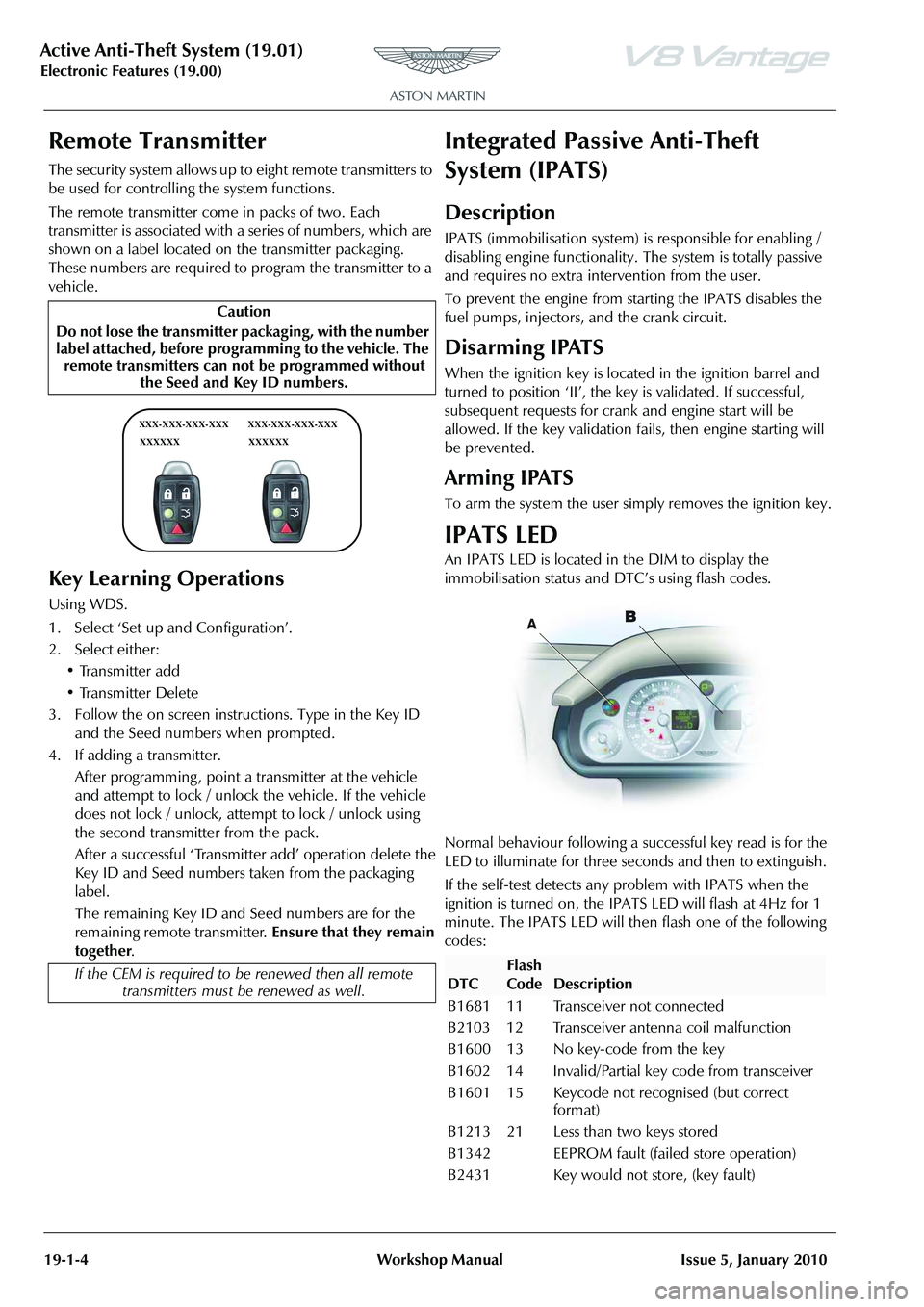
The remote transmitter come in packs of two. Each
transmitter is associated with a
series of numbers, which are
shown on a label located on the transmitter packaging.
These numbers are required to program the transmitter to a
vehicle.
Key Learning Operations
Using WDS.
1. Select ‘Set up and Configuration’.
2. Select either:
• Transmitter add
• Transmitter Delete
3. Follow the on screen instructions. Type in the Key ID and the Seed numbers when prompted.
4. If adding a transmitter. After programming , point a transmitter at the vehicle
and attempt to lock / unlock the vehicle. If the vehicle
does not lock / unlock, attempt to lock / unlock using
the second transmitter from the pack.
After a successful ‘Transmitter add’ operation delete the
Key ID and Seed numbers taken from the packaging
label.
The remaining Key ID and Seed numbers are for the
remaining remote transmitter. Ensure that they remain
together .
Integrated Passive Anti-Theft
System (IPATS)
Description
IPATS (immobilisation system) is responsible for enabling /
disabling engine functionality. The system is totally passive
and requires no extra inte rvention from the user.
To prevent the engine from starting the IPATS disables the
fuel pumps, injectors, and the crank circuit.
Disarming IPATS
When the ignition key is located in the ignition barrel and
turned to position ‘II’, the key is validated. If successful,
subsequent requests for crank and engine start will be
allowed. If the key validation fa ils, then engine starting will
be prevented.
Arming IPATS
To arm the system the user simply removes the ignition key.
IPATS LED
An IPATS LED is located in the DIM to display the
immobilisation status and DTC’s using flash codes.
Normal behaviour following a su ccessful key read is for the
LED to illuminate for three seconds and then to extinguish.
If the self-test detects any problem with IPATS when the
ignition is turned on, the IPAT S LED will flash at 4Hz for 1
minute. The IPATS LED will then flash one of the following
codes:
Caution
Do not lose the transmitter packaging, with the number
label attached, before progra mming to the vehicle. The
remote transmitters can not be programmed without the Seed and Key ID numbers.
If the CEM is required to be renewed then all remote
transmitters must be renewed as well.
XXX-XXX-XXX-XXX
XXXXXX XXX-XXX-XXX-XXX
XXXXXX
DTC
Flash
Code
Description
B1681 11 Transceiver not connected
B2103 12 Transceiver antenna coil malfunction
B1600 13 No key-code from the key
B1602 14 Invalid/Partial key code from transceiver
B1601 15 Keycode not recognised (but correct format)
B1213 21 Less than two keys stored
B1342 EEPROM fault (failed store operation)
B2431 Key would not store, (key fault)