wheel torque ASTON MARTIN V8 VANTAGE 2010 Workshop Manual
[x] Cancel search | Manufacturer: ASTON MARTIN, Model Year: 2010, Model line: V8 VANTAGE, Model: ASTON MARTIN V8 VANTAGE 2010Pages: 947, PDF Size: 43.21 MB
Page 20 of 947

Front End (01.02)
Body System (01.00)1-2-2 Workshop Manual Issue 5, January 2010
Front Undertray-Remove and Install
Removal
1. Use the applicable equipment to lift the vehicle and make it safe.
2. Remove the 14 Torx screws that attach the front undertray to the body.
3. Remove the front undertray.
Install
1. Put the front undertray in position.
2. Install and torque tighen the 14 Torx screws trhat attach the front undertray to the vehicle.
3. Lower the vehicle.
Rear Undertray - Renew (Coupe only)
Removal
1. Raise the vehicle and make it safe.
2. Remove the 10 screws that attach the rear undertray to
the body.
S-01-02-PB-01
3. Remove rear undertray.
S-01-02-PB-02
Installation
1. Put the rear undertray in posiiton.
2. Install and tighten the 10 screws that attach the rear undertray to the vehicle.
S-01-02-PB-01
3. Lower the vehicle.
Rear Undertray - Renew (Roadster only)
Removal
1. Use the applicable equipment to lift the vehicle and make it safe.
2. Remove the 18 of the 21 screws that attach the rear undertray to the body.
3. Lower the vehicle wheels onto blocks to get access to the remaining screws that attach the rear undertray to
the body. 4. Remove the remaining three screws that attach the rear
undertray to the body.
5. Remove the rear undertray.
Install
1. Put the rear undertray in position.
2. Install and tighten the 21 scrwes that attach the rear undertray to the body.
3. Lift the vehicle.
4. Remove the blocks.
5. Lower the vehicle.
Undertray, Vehicle Set - Renew
Removal
1. Raise vehicle on ramp.
2. Remove front undertray (see Workshop Manual 01.02.NB - Front undertray - Renew).
3. Remove rear undertray (see Workshop Manual 01.02.PB - Rear undertray - Renew).
4. Remove centre undertray (see Workshop Manual 01.02.MB - Centre undertray - Renew).
Installation
1. With assistance, install centre undertray (see Workshop Manual 01.02.MB - Centre undertray - Renew).
2. With assistance, install front undertray (see Workshop Manual 01.02.NB - Front undertray - Renew).
3. With assistance, install rear undertray (see Workshop Manual 01.02.PB - Rear undertray - Renew).
4. Lower vehicle on ramp.
RH/LH Front Wheel Ar ch Liner - Renew
Removal
1. Remove centre undertray, Roadster only (see Workshop
Manual procedure 01.02.MB Undertray - Centre -
Renew).
2. Raise vehicle on ramp.
3. Remove road wheel(s).
Repair Operation Time (ROT)
Repair Operation Time (ROT)
Repair Operation Time (ROT)
WARNING
THE REAR UNDERTRAY IS HEAVY. GET THE HELP OF ANOTHER PERSON WHEN YOU MOVE THE REAR
UNDERTRAY. IF YOU DO NOT YOU CAN BE INJURED.
Repair Operation Time (ROT)
ItemCode
Undertray Vehicle Set-Renew 01.02.PD
Repair Operation Time (ROT)
ItemCode
Wheel Arch Liner-Renew RH01.02.GB
Wheel Arch Liner-Renew LH01.02.FB
Page 32 of 947
Body Closures (01.03)
Body System (01.00)1-3-6 Workshop Manual May 2007
19. Install inner and outer cable to external door handle.
20. Connect multiplug to door latch.
21. Install rear weatherstrip to glass channel and door frame. Install fir tree trim pins (x3)
22. Install seal to inner door aperture.
23. Position door mirror, install and torque tighten Torx bolts (x3) and screw (glass channel).
24. Connect door mirror multip lug, secure harness with fir
tree clips (x2) and adhesive clip.
25. Install rubber cheater to door frame, secure with fir tree trim pins (x3).
26. Install glass regulator as sembly into door frame.
27. Install and torque tighten nuts (x4) and Torx screws (x3) securing regulator assembly to door frame.
28. Connect multiplug to glass regulator.
29. Install door glass, install clamp bolts (x2), align marks on glass to rear clamp. Do not torque tighten at this stage.
30. Install fixed glass, ensure rubber surround is correctly installed.
31. Connect multiplug to side impact sensor, position
mounting plate, install and torque bolts (x3).
32. Position door control modu le, connect multiplugs (x3).
Install and torque tighten bolts (x4).
33. Position door speaker, install and torque tighten screws (x3). Connect multiplug to speaker.
34. Position door trimboard, connect multiplugs (x2).
35. Install trimboard to door frame, secure in clips.
36. Install and tighten screws (x5).
37. Install LH door assembly (see Workshop Manual procedure 01.03.FA Door Assembly - LH - Remove for
Access and Refit).
38. Battery isolation switch ‘ON’.
39. Glass front door - LH - Adjust and reset (see Workshop Manual procedure 01.11.BD Glass - Front Door - LH -
Adjust and Reset).
RH/LH Door Assembly-Remove/Refit
Removal
1. Switch on ignition, set door glass to half-way down position (this is to access door glass screw clamps on
door renew - 01.05.CB).
2. Battery isolation switch ‘OFF’.
3. Raise vehicle on ramp.
4. Remove road wheel(s),
5. Release rear part of whee l arch liner, screws (x7),
disconnect door check rod.
6. Pull back sealing boot and disconnect door multiplug.
7. Loosen the door hinge Torx screws (x2). 8. With assistance, lift door off support studs.
9. Withdraw the door from the vehicle and install on Door
Service Trolley (501 - F111).
10. Remove and discard hinge Torx screws (Patchlok).
Installation
1. Protect vehicle bodywork.
2. Install new hinge Torx screws.
3. With assistance, remove door from trolley (501 - F111),
position door to vehicle.
4. Align door to upper and lower hinges and install on hinge studs.
5. Connect the door check rod and install wheel arch liner, screws (x7).
6. Tighten hinge Torx screws (x2) (torque).
7. Connect multiplug and install boot.
8. Battery isolation switch ‘ON’.
9. Install road wheel(s).
10. Lower vehicle on ramp.
Front Door Hinge (One Side) - Renew
Removal
1. Remove LH/RH door assemb ly (see Workshop Manual
procedure 01.03.FA/01.03.EA Door Assembly - LH/RH -
Remove for Access and Refit).
2. Remove bolts (x4) securing upper and lower door hinges to body.
3. Remove hinges, note position of shims (if fitted) collect
rubber seals (x2).
4. Remove bolts (x2) securing upper and lower hinges to door, remove hinges (x2). No te fitted position of shims
(if fitted).
Installation
1. Position hinges to body, install rubber seals (x2) and shims (if fitted).
2. Install bolts (x4) securing hi nges to body. Do not torque
tighten bolts at this stage.
3. Position hinges (x2) to door. Install bolts (x2). Do not torque tighten at this stage.
4. Install LH/RH door assemb ly (see Workshop Manual
procedure 01.03.FA/01.03.EA Door Assembly - LH/RH -
Remove for Access and Refit).
5. Carry out preliminary hinge set-up.
6. Gently close door and check for acceptable initial installation.
7. Align the door, manoeuvre the door to achieve correct gaps and flush fit; (add/remove shims as required).
8. Open door, tighten bolts. Do not torque tighten at this stage.
9. Close door, re-check fitment and alignment.Repair Operation Time (ROT)
Repair Operation Time (ROT)
ItemCode
Front Door Hinge (One Side) Renew 01.03.FB
Page 62 of 947

Exterior Trim (01.08)
Body System (01.00)1-5-2 Workshop Manual May 2007
RH Wing Side Strake - Renew
Removal
1. Disconnect vehicle battery.
2. Raise vehicle on ramp.
3. Remove mesh - RH side strake (see Workshop Manual procedure 01.08.CE Mesh - Side Strake - RH - Renew).
4. Remove Torx screw, (inside A-post) securing side strake to body.
5. Remove nut securing side strake to RH inner fender.
6. Remove side strake.
Installation
1. Install side strake, install and tighten nut and Torx screw.
2. Install mesh - RH side strake (see Workshop Manual procedure 01.08.CE Mesh - Side Strake - RH - Renew).
3. Lower vehicle on ramp.
4. Connect vehicle battery.
LH Wing Side Strake - Renew
Removal
1. Raise vehicle on ramp.
2. Remove mesh - LH side strake (see Workshop Manual procedure 01.08.CF Mesh - Side Strake - LH - Renew).
3. Remove nuts (x3) mesh to side strake.
4. Remove mesh.
5. Remove screw inside A-post side strake to body.
6. Remove nut side strake to wheel arch.
7. Remove side strake.
Installation
1. Install side strake, nut and screw.
2. Position mesh to side strake and install nuts (x3).
3. Install mesh - LH side strake (see Workshop Manual procedure 01.08.CF Mesh - Side Strake - LH - Renew).
4. Lower vehicle on ramp.
Channel Assembly Divider Bar - Renew
Removal
1. Remove window regulator (see Workshop Manual procedure 01.11.DA Regulator - Door Glass - RH -
Renew). 2. Remove fixed glass (see Workshop Manual procedure
01.11.BG Glass - Front Door - Fixed RH - Renew).
3. Remove seal.
4. Remove screw, divider bar to mirror (see Figure 1).
5. Remove nut (hold stud with Allen key) divider bar to door and remove (see Figure 2).
Installation
1. Install bar and nut (hold stud with Allen key).
2. Install screw, divider bar to mirror (Do not tighten at this point).
3. Install seal.
4. Adjust bar. Rotate Allen stud in centre in/out until desired alignment of bar is achieved, then torque fixings.
5. Install fixed glass (see Workshop Manual procedure 01.11.BG Glass - Front Door - Fixed RH - Renew).
6. Install window regulator (see Workshop Manual procedure 01.11.DA Regulator - Door Glass - RH -
Renew).
Repair Operation Time (ROT)
Repair Operation Time (ROT)
Repair Operation Time (ROT)
Figure 1
Figure 2
A0108170
A0108171
Page 93 of 947
Instrument Panel (IP) (01.12)
Body System (01.00)
Issue 5, January 2010 Workshop Manual 1-9-5
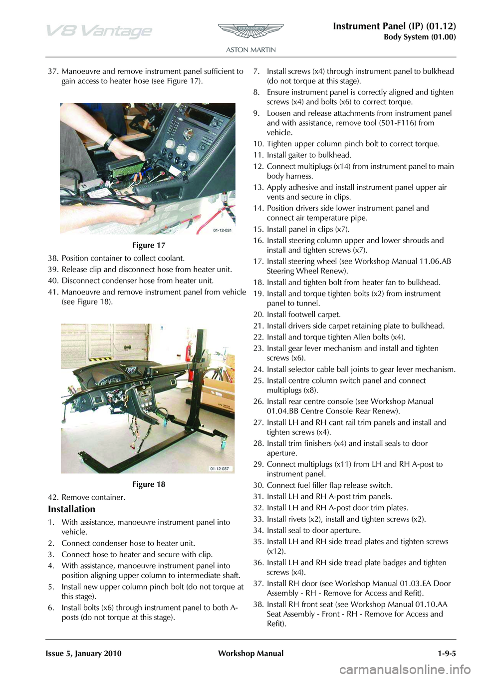
37. Manoeuvre and remove inst rument panel sufficient to
gain access to heater hose (see Figure 17).
38. Position container to collect coolant.
39. Release clip and disconne ct hose from heater unit.
40. Disconnect condenser hose from heater unit.
41. Manoeuvre and remove inst rument panel from vehicle
(see Figure 18).
42. Remove container.
Installation
1. With assistance, manoeuvre instrument panel into vehicle.
2. Connect condenser hose to heater unit.
3. Connect hose to heater and secure with clip.
4. With assistance, manoeuvre instrument panel into position aligning upper column to intermediate shaft.
5. Install new upper column pinch bolt (do not torque at this stage).
6. Install bolts (x6) through instrument panel to both A- posts (do not torque at this stage). 7. Install screws (x4) through
instrument panel to bulkhead
(do not torque at this stage).
8. Ensure instrument panel is correctly aligned and tighten screws (x4) and bolts (x6) to correct torque.
9. Loosen and release attachme nts from instrument panel
and with assistance, remove tool (501-F116) from
vehicle.
10. Tighten upper column pinch bolt to correct torque.
11. Install gaiter to bulkhead.
12. Connect multiplugs (x14) fr om instrument panel to main
body harness.
13. Apply adhesive and install instrument panel upper air
vents and secure in clips.
14. Position drivers side lower instrument panel and connect air temperature pipe.
15. Install panel in clips (x7).
16. Install steering column upper and lower shrouds and install and tighten screws (x7).
17. Install steering wheel (see Workshop Manual 11.06.AB Steering Wheel Renew).
18. Install and tighten bolt from heater fan to bulkhead.
19. Install and torque tighten bolts (x2) from instrument panel to tunnel.
20. Install footwell carpet.
21. Install drivers side carpet retaining plate to bulkhead.
22. Install and torque tighten Allen bolts (x4).
23. Install gear lever mechanism and install and tighten screws (x6).
24. Install selector cable ball joints to gear lever mechanism.
25. Install centre column switch panel and connect multiplugs (x8).
26. Install rear centre cons ole (see Workshop Manual
01.04.BB Centre Console Rear Renew).
27. Install LH and RH cant rail trim panels and install and tighten screws (x4).
28. Install trim finishers (x4) and install seals to door aperture.
29. Connect multiplugs (x11) from LH and RH A-post to
instrument panel.
30. Connect fuel filler flap release switch.
31. Install LH and RH A-post trim panels.
32. Install LH and RH A-post door trim plates.
33. Install rivets (x2), insta ll and tighten screws (x2).
34. Install seal to door aperture.
35. Install LH and RH side tread plates and tighten screws (x12).
36. Install LH and RH side tread plate badges and tighten screws (x4).
37. Install RH door (see Workshop Manual 01.03.EA Door Assembly - RH - Remove for Access and Refit).
38. Install RH front seat (see Workshop Manual 01.10.AA Seat Assembly - Front - RH - Remove for Access and
Refit).
Figure 17
Figure 18
Page 123 of 947
Handles and Lock Mechanisms (01.14)
Body System (01.00)
May 2007 Workshop Manual 1-10-3
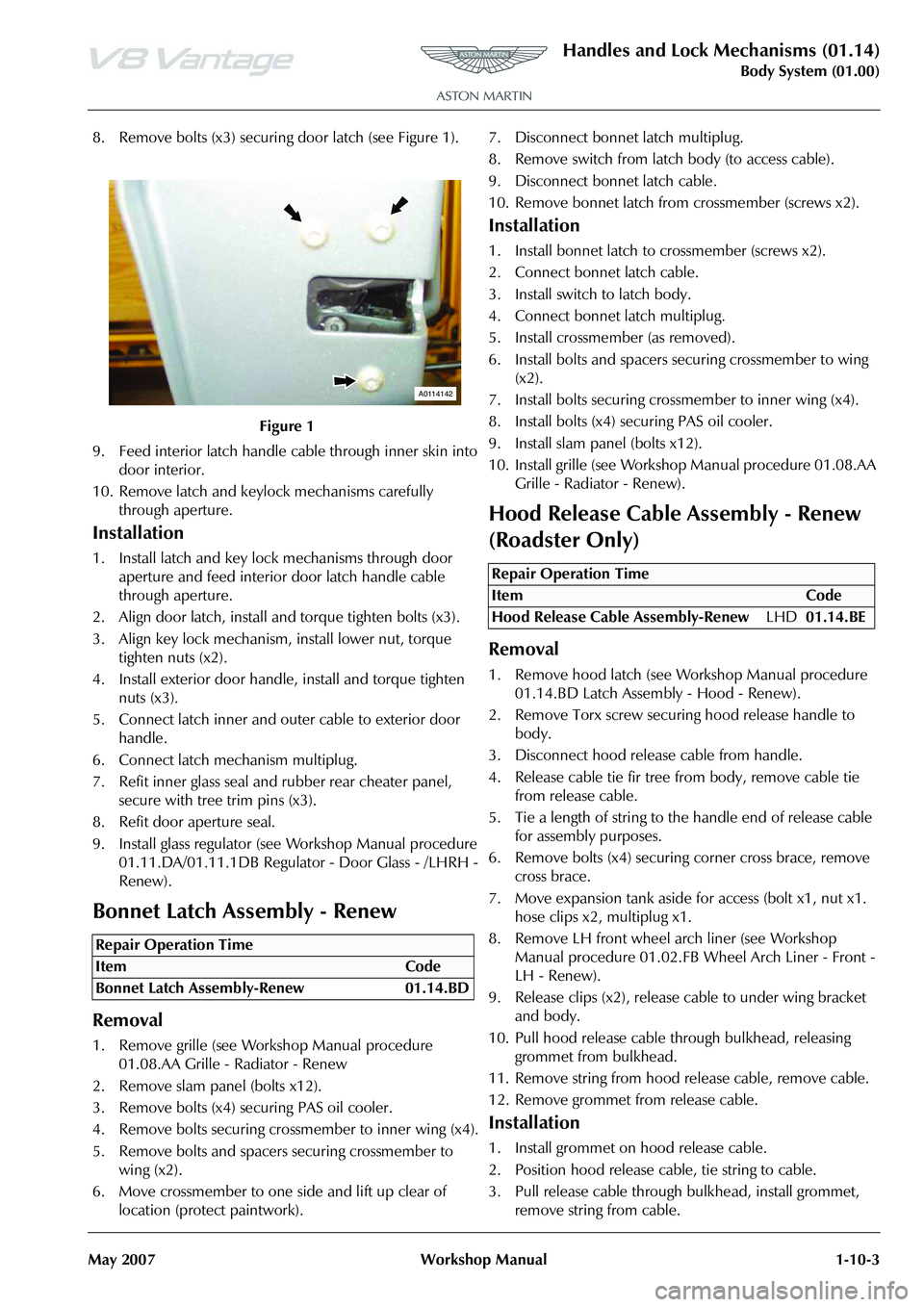
8. Remove bolts (x3) securing door latch (see Figure 1).
9. Feed interior latch handle cable through inner skin into door interior.
10. Remove latch and keylock mechanisms carefully through aperture.
Installation
1. Install latch and key lock mechanisms through door aperture and feed interior door latch handle cable
through aperture.
2. Align door latch, install and torque tighten bolts (x3).
3. Align key lock mechanism, install lower nut, torque tighten nuts (x2).
4. Install exterior door handle, install and torque tighten nuts (x3).
5. Connect latch inner and outer cable to exterior door handle.
6. Connect latch mechanism multiplug.
7. Refit inner glass seal and rubber rear cheater panel, secure with tree trim pins (x3).
8. Refit door aperture seal.
9. Install glass regulator (see Workshop Manual procedure 01.11.DA/01.11.1DB Regulato r - Door Glass - /LHRH -
Renew).
Bonnet Latch Assembly - Renew
Removal
1. Remove grille (see Workshop Manual procedure 01.08.AA Grille - Radiator - Renew
2. Remove slam panel (bolts x12).
3. Remove bolts (x4) securing PAS oil cooler.
4. Remove bolts securing crossmember to inner wing (x4).
5. Remove bolts and spacers securing crossmember to wing (x2).
6. Move crossmember to one side and lift up clear of location (protect paintwork). 7. Disconnect bonnet latch multiplug.
8. Remove switch from latch body (to access cable).
9. Disconnect bonnet latch cable.
10. Remove bonnet latch from
crossmember (screws x2).
Installation
1. Install bonnet latch to crossmember (screws x2).
2. Connect bonnet latch cable.
3. Install switch to latch body.
4. Connect bonnet latch multiplug.
5. Install crossmember (as removed).
6. Install bolts and spacers securing crossmember to wing
(x2).
7. Install bolts securing cros smember to inner wing (x4).
8. Install bolts (x4) securing PAS oil cooler.
9. Install slam panel (bolts x12).
10. Install grille (see Workshop Manual procedure 01.08.AA
Grille - Radiator - Renew).
Hood Release Cable Assembly - Renew
(Roadster Only)
Removal
1. Remove hood latch (see Wo rkshop Manual procedure
01.14.BD Latch Assembly - Hood - Renew).
2. Remove Torx screw securi ng hood release handle to
body.
3. Disconnect hood releas e cable from handle.
4. Release cable tie fir tree fr om body, remove cable tie
from release cable.
5. Tie a length of string to the handle end of release cable for assembly purposes.
6. Remove bolts (x4) securing corner cross brace, remove
cross brace.
7. Move expansion tank aside for access (bolt x1, nut x1. hose clips x2, multiplug x1.
8. Remove LH front wheel arch liner (see Workshop Manual procedure 01.02.FB Wheel Arch Liner - Front -
LH - Renew).
9. Release clips (x2), release cable to under wing bracket and body.
10. Pull hood release cable th rough bulkhead, releasing
grommet from bulkhead.
11. Remove string from hood release cable, remove cable.
12. Remove grommet from release cable.
Installation
1. Install grommet on hood release cable.
2. Position hood release cable, tie string to cable.
3. Pull release cable through bulkhead, install grommet, remove string from cable.
Figure 1
Repair Operation Time
ItemCode
Bonnet Latch Assembly-Renew 01.14.BD
A0114142
Repair Operation Time
ItemCode
Hood Release Cable Assembly-Renew LHD01.14.BE
Page 124 of 947
Handles and Lock Mechanisms (01.14)
Body System (01.00)1-10-4 Workshop Manual May 2007
4. Connect release cable to hand le, position handle, install
and tighten Torx screw.
5. Install and secure hood release cable with fir tree clip.
6. Install hood latch assembly (see Workshop Manual procedure 01.14.BD Latch Assembly - Hood - Renew).
7. Install and secure hood release cable with fir tree clips to under wing bracket and body.
8. Install expansion tank (bolt x1, nut x1, hose clips x2, multiplug x1.
9. Install corner cross brace, install bolts (x4)(torque tighten bolts with vehicle on level floor).
10. Install LH front wheel arch liner (see Workshop Manual
procedure 01.02.FB Wheel Arch Liner - Front - LH -
Renew).
11. Top-up cooling system.
Bonnet Secondary Latch Assembly -
Renew
Removal
1. Open bonnet.
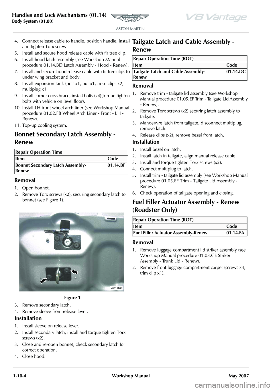
2. Remove Torx screws (x2), securing secondary latch to bonnet (see Figure 1).
3. Remove secondary latch.
4. Remove sleeve from release lever.
Installation
1. Install sleeve on release lever.
2. Install secondary latch, install and torque tighten Torx screws (x2).
3. Close and re-open bonnet, check secondary latch for correct operation.
4. Close hood.
Tailgate Latch and Cable Assembly -
Renew
Removal
1. Remove trim - tailgate lid assembly (see Workshop Manual procedure 01.05.EF Trim - Tailgate Lid Assembly
- Renew).
2. Remove Torx screws (x2) securing latch assembly to
tailgate.
3. Manoeuvre latch from tailgate, disconnect multiplug, remove latch.
4. Release clips (x2), remove bezel from latch.
Installation
1. Install bezel on latch.
2. Install latch in tailgate, align manual release cable.
3. Install and torque tighten Torx screws (x2).
4. Connect multiplug to latch.
5. Install trim - tailgate lid assembly (see Workshop Manual procedure 01.05.EF Trim - Tailgate Lid Assembly -
Renew).
6. Check operation of tailgate opening and closing.
Fuel Filler Actuator Assembly - Renew
(Roadster Only)
Removal
1. Remove luggage compartment lid striker assembly (see Workshop Manual procedure 01.03.GE Striker
Assembly - Trunk Lid - Renew).
2. Remove front luggage compartment carpet (screws x4, trim clip x1).
Repair Operation Time
ItemCode
Bonnet Secondary Latch Assembly-
Renew 01.14.BF
Figure 1
A0114172
Repair Operation Time (ROT)
ItemCode
Tailgate Latch and Cable Assembly-
Renew 01.14.DC
Repair Operation Time (ROT)
ItemCode
Fuel Filler Actuator Assembly-Renew 01.14.FA
Page 132 of 947
Wipers and Washer System (01.16)
Body System (01.00)1-11-2 Workshop Manual Issue 4,November, 2008
Specifications
Maintenance
Windscreen Wiper Motor Assembly -
Renew
Removal
1. Remove wiper linkage.
2. Remove arm from motor (nut x1).
3. Remove motor from plate (bolts x3).
Installation
1. Install motor to plate (bolts x3).
2. Ensure wiper motor is in the ‘PARK’ position.
3. Install arm from motor (nut x1), using special tool.
4. Install wiper linkage.
Wiper Linkage Assembly - Renew
Removal
1. Remove brake booster (see Workshop Manual procedure 06.07.DE/06.07.DG Master Cylinder and
Vacuum Booster - Brake - Renew).
2. Remove inlet manifold (see Workshop Manual procedure 03.01.BB/03.01.BF Gasket - Manifold
Assembly - Intake Upper - Renew).
3. Remove wiper arm drivers si de (see Workshop Manual
procedure 01.16.AD Arm Asse mbly - Wiper - Driver -
Renew).
4. Remove wiper arm passengers side (see Workshop Manual procedure 01.16.AE Arm Assembly - Wiper -
Passenger - Renew).
5. Unclip expansion tank hose for access. 6. Remove sound deadening (trim buttons x6).
7. Remove seal from spindle.
8. Remove nuts (x2) from heatshield to move aside.
9. Unclip wiper motor harness (x2) LHS.
10. Unclip windscreen heater harness RHS.
11. Disconnect motor multiplu
g and unclip harness (x2).
12. To prevent damage, protect A/C pipe with tape before
wiper linkage removal.
13. Remove plate securing scre ws (x10) (through plenum).
14. Remove plate securing bolts (x8) (under bonnet).
15. Remove wiper linkage.
Installation
1. Install wiper linkage.
2. Install plate securing bolts (x8) (under bonnet).
3. Install plate securing scre ws (x10) (through scuttle
panel).
4. Connect motor multiplug and clip harness (x2).
5. Clip harness LHS.
6. Clip harness RHS.
7. Refit heatshield and install nuts (x2).
8. Install seal to spindle.
9. Install sound deadening (re-stick, trim buttons x6).
10. Clip expansion tank hose.
11. Install wiper arm drivers side (see Workshop Manual procedure 01.16.AD Arm Assembly - Wiper - Driver -
Renew).
12. Install wiper arm passengers side (see Workshop Manual
procedure 01.16.AE Arm Asse mbly - Wiper - Passenger
- Renew).
13. Install inlet manifold (see Workshop Manual procedure 03.01.BB/03.01.BF Gasket - Manifold Assembly - Intake
Upper - Renew).
14. Install brake booster (see Workshop Manual procedure 06.07.DE/06.07.DG Master Cylinder and Vacuum
Booster - Brake - Renew).
Windshield Wash Tube - Renew
Removal
1. Remove RH wheel arch liner (see Workshop Manual Procedure 01.02.GB Wheel Arch Liner - Front - RH -
Renew).
2. Place container to catch fluid.
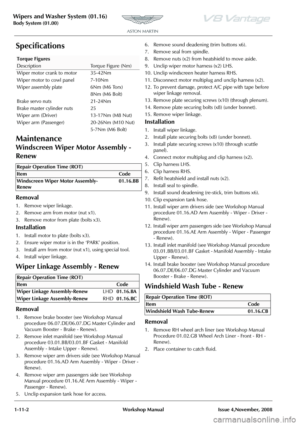
Torque Figures
DescriptionTorque Figure (Nm)
Wiper motor crank to motor 35-42Nm
Wiper motor to cowl panel 7-10Nm
Wiper assembly plate 6Nm (M6 Torx) 8Nm (M6 Bolt)
Brake servo nuts 21-24Nm
Brake master cylinder nuts 25
Wiper arm (Driver) 13-17Nm (M8 Nut)
Wiper arm (Passenger) 20-26Nm (M10 Nut) 5-7Nm (M6 Bolt)
Repair Operation Time (ROT)
Repair Operation Time (ROT)
Repair Operation Time (ROT)
ItemCode
Windshield Wash Tube-Renew 01.16.CB
Page 210 of 947

Bumpers (01.19)
Body System (01.00)1-13-2 Workshop Manual May 2007
Specifications
Maintenance
Front Bumper Cover - Renew
Removal
1. Raise vehicle on ramp.
2. Remove front number plate and plinth (see Workshop Manual procedure 01.19.BD Licence Plate - Plinth
Assembly - Front - Renew).
3. Remove valance (see Workshop Manual procedure 01.19.AF Panel - Front Valance - Renew).
4. Remove screws (x2) securing front of undertray to bumper (see Figure 1).
5. Remove screws (x5) LH front wheel arch liner to bumper.
6. Remove screws (x5) RH front wheel arch liner to bumper.
7. Remove bolts (x3 securing LH air box to mounting brackets.
8. Remove bolts (x3 securing RH air box to mounting brackets. 9. Remove bolts (x6) securing bumper to front wing (see
Figure 2)
.
10. With assistance, release bumper from clips (x2) and
remove bumper (see Figure 3).
11. Remove mesh (clips x8).
Installation
1. Install mesh (clips x8).
2. With assistance position bumper and secure in clips (x2).
3. Install bolts (x6) bumper to front wing.
4. Install bolts (x3 securing RH air box to mounting brackets.
5. Install bolts (x3 securing LH air box to mounting brackets.
6. Install screws (x5) LH front wheel arch liner to bumper.
7. Install screws (x5) RH front wheel arch liner to bumper.
8. Install screws (x2) securing front undertray to bumper.
Torque Figures
DescriptionNm
Front Bumper to bumper bracket 4-5
Rear Bumper to Bumper Bracket 2-3
Repair Operation Time (ROT)
01-19-005
Figure 2
Figure 3
Remove Bolts x6
Front Bumper
01-19-001
01-19-004
Page 224 of 947
Subframes (02.03)
Frame and Mounting (02.00)
2-1-2 Workshop Manual May 2007
Frame and Mounting (02.00)
Subframes (02.03)
Specifications
Maintenance
Front Subframe-Renew
Removal
1. Switch battery isolation switch ‘OFF’.
2. Raise vehicle on ramp.
3. Remove RH wheel arch liner (see Workshop Manual procedure 01.02.GB Wheel Arch Liner - Front - RH -
Renew).
4. Remove LH wheel arch liner (see Workshop Manual procedure 01.02.FB Wheel Arch Liner - Front - LH -
Renew)
5. Remove road wheel/s.
6. Remove front spring/damper assemblies (see Workshop Manual procedure 04.03.AA Spring and Damper
Assembly - Front Pair - Renew).
7. Remove nuts (x2) from track rod ends to vertical link.
8. Using special tool 204-523, release track rod end from vertical link.
9. Disconnect ABS sensor multiplugs then release sensor harness clips (x6) from upper suspension arm and
vertical link.
10. Disconnect brake pad wear sensor multiplug then release sensor harness clips (x2) from upper suspension
arms. 11. Remove Allen bolts (x4) from brake callipers to vertical
link and tie callipers aside.
12. Remove Torx screws (x4) from brake disc to hub and remove brake disc.
13. Remove anti-roll bar links nuts (x2) and washers (x2).
14. Remove ride height sensor link nut and bolt from lower
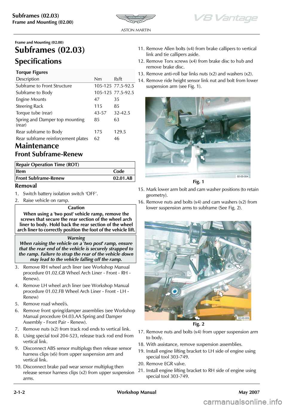
suspension arm (see Fig. 1).
15. Mark lower arm bolt and cam washer positions (to retain
geometry).
16. Remove nuts and bolts (x4) and cam washers (x2) from lower suspension arms to subframe (See Fig. 2).
17. Remove nuts and bolts (x4) from upper suspension arm to body.
18. With assistance, remove suspension assemblies.
19. Install engine lifting bracket to LH side of engine using special tool 303-749.
20. Remove EGR valve.
21. Install engine lifting bracket to RH side of engine using special tool 303-749.
Torque Figures
DescriptionNmIb/ft
Subframe to Front Structure 105-125 77.5-92.5
Subframe to Body 105-125 77.5-92.5
Engine Mounts 47 35
Steering Rack 115 85
Torque tube (rear) 43-57 32-42.5
Spring and Damper top mounting
(rear) 85 63
Rear subframe to Body 175 129.5
Rear subframe reinforcement plates 62 46
Repair Operation Time (ROT)
Warning
When raising the vehicle on a 'two post' ramp, ensure
that the rear end of the vehi cle is securely strapped to
the ramp. Failure to strap th e rear of the vehicle down
may lead to the vehicl e falling off the ramp.
Fig. 1
Fig. 2
Page 225 of 947
Subframes (02.03)
Frame and Mounting (02.00)
May 2007 Workshop Manual 2-1-3
22. Install cross brace support brackets 303-021-02 (x6).
23. Support engine using special tool SPX M553D.
24. Remove undertray (see Workshop Manual procedure 01.02.NB Undertray - Front - Renew).
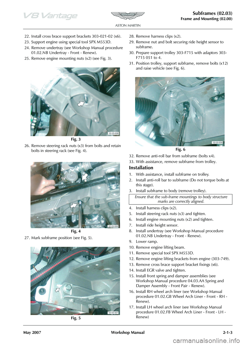
25. Remove engine mounting nuts (x2) (see Fig. 3).
26. Remove steering rack nuts (x3) from bolts and retain bolts in steering rack (see Fig. 4).
27. Mark subframe position (see Fig. 5). 28. Remove harness clips (x2).
29. Remove nut and bolt securi
ng ride height sensor to
subframe.
30. Prepare support trolley 30 3-F715 with adaptors 303-
F715 051 to 4.
31. Position trolley, support subframe, remove bolts (x12)
and raise vehicle (see Fig. 6).
32. Remove anti-roll bar from subframe (bolts x4).
33. With assistance, remove subframe from trolley.
Installation
1. With assistance, install subframe on trolley.
2. Install anti-roll bar to subframe (Do not torque bolts at this stage).
3. Install subframe to body (remove trolley).
4. Install harness clips (x2).
5. Install steering rack nuts (x3) and tighten.
6. Install engine mounting nuts (x2) and tighten.
7. Install ride height sensor.
8. Install undertray (see Workshop Manual procedure 01.02.NB Undertray - Front - Renew).
9. Lower ramp.
10. Remove engine lifting beam.
11. Remove special tool SPX M553D.
12. Remove engine lifting brack ets from engine (303-749).
13. Remove cross brace suppo rt bracket fixings (x6).
14. Install EGR valve and tighten.
15. Install front spring and damper assemblies (see Workshop Manual procedure 04.03.AA Spring and
Damper Assembly - Front Pair - Renew).
16. Install RH wheel arch li ner (see Workshop Manual
procedure 01.02.GB Wheel Arch Liner - Front - RH -
Renew).
17. Install LH wheel arch liner (see Workshop Manual procedure 01.02.FB Wheel Arch Liner - Front - LH -
Renew)
Fig. 3
Fig. 4
Fig. 5
Fig. 6
Ensure that the sub-frame mo untings to body structure
marks are correctly aligned.