instrument cluster AUDI A3 1995 8L / 1.G ATW Engine Additional Signals Workshop Manual
[x] Cancel search | Manufacturer: AUDI, Model Year: 1995, Model line: A3, Model: AUDI A3 1995 8L / 1.GPages: 27, PDF Size: 0.12 MB
Page 2 of 27

24-156
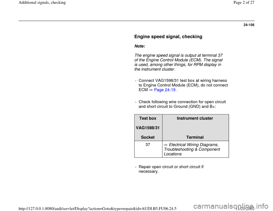
Engine speed signal, checking
Note:
The engine speed signal is output at terminal 37
of the Engine Control Module (ECM). The signal
is used, among other things, for RPM display in
the instrument cluster.
- Connect VAG1598/31 test box at wiring harness
to Engine Control Module (ECM), do not connect
ECM Page 24
-19
.
- Check following wire connection for open circuit
and short circuit to Ground (GND) and B+:
Test box
VAG1598/31
Socket
Instrument cluster
Terminal
37 Electrical Wiring Diagrams,
Troubleshooting & Component
Locations
- Repair open circuit or short circuit if
necessary.
Pa
ge 2 of 27 Additional si
gnals, checkin
g
11/21/2002 htt
p://127.0.0.1:8080/audi/servlet/Dis
play?action=Goto&t
yp
e=re
pair&id=AUDI.B5.FU06.24.5
Page 3 of 27

24-157
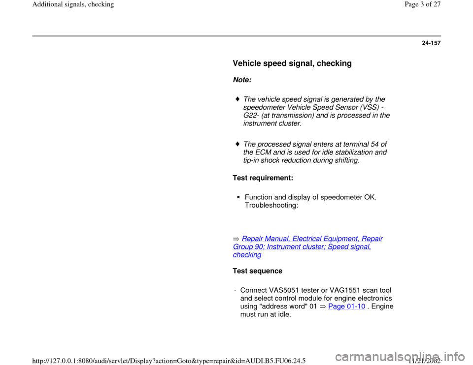
Vehicle speed signal, checking
Note:
The vehicle speed signal is generated by the
speedometer Vehicle Speed Sensor (VSS) -
G22- (at transmission) and is processed in the
instrument cluster.
The processed signal enters at terminal 54 of
the ECM and is used for idle stabilization and
tip-in shock reduction during shifting.
Test requirement:
Function and display of speedometer OK.
Troubleshooting:
Repair Manual, Electrical Equipment, Repair
Group 90; Instrument cluster; Speed signal, checking
Test sequence
- Connect VAS5051 tester or VAG1551 scan tool
and select control module for engine electronics
using "address word" 01 Page 01
-10
. Engine
must run at idle.
Pa
ge 3 of 27 Additional si
gnals, checkin
g
11/21/2002 htt
p://127.0.0.1:8080/audi/servlet/Dis
play?action=Goto&t
yp
e=re
pair&id=AUDI.B5.FU06.24.5
Page 5 of 27

24-159
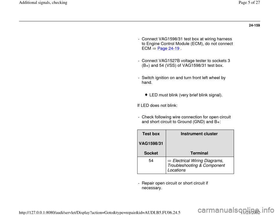
- Connect VAG1598/31 test box at wiring harness
to Engine Control Module (ECM), do not connect
ECM Page 24
-19
.
- Connect VAG1527B voltage tester to sockets 3
(B+) and 54 (VSS) of VAG1598/31 test box.
- Switch ignition on and turn front left wheel by
hand.
LED must blink (very brief blink signal).
If LED does not blink:
- Check following wire connection for open circuit
and short circuit to Ground (GND) and B+:
Test box
VAG1598/31
Socket
Instrument cluster
Terminal
54 Electrical Wiring Diagrams,
Troubleshooting & Component
Locations
- Repair open circuit or short circuit if
necessary.
Pa
ge 5 of 27 Additional si
gnals, checkin
g
11/21/2002 htt
p://127.0.0.1:8080/audi/servlet/Dis
play?action=Goto&t
yp
e=re
pair&id=AUDI.B5.FU06.24.5
Page 14 of 27

24-166
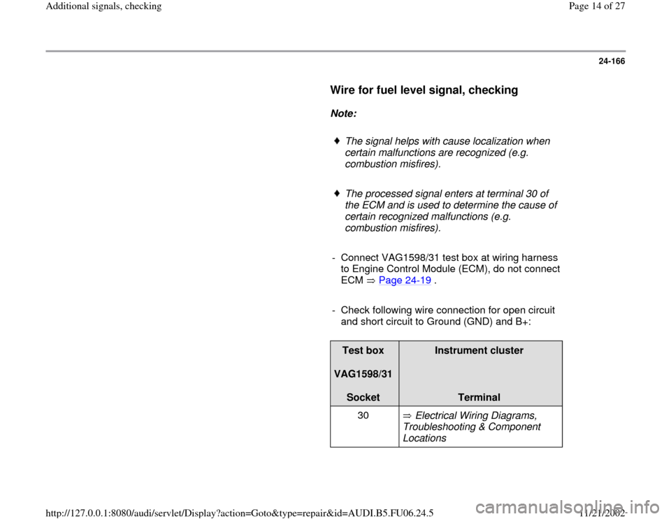
Wire for fuel level signal, checking
Note:
The signal helps with cause localization when
certain malfunctions are recognized (e.g.
combustion misfires).
The processed signal enters at terminal 30 of
the ECM and is used to determine the cause of
certain recognized malfunctions (e.g.
combustion misfires).
- Connect VAG1598/31 test box at wiring harness
to Engine Control Module (ECM), do not connect
ECM Page 24
-19
.
- Check following wire connection for open circuit
and short circuit to Ground (GND) and B+:
Test box
VAG1598/31
Socket
Instrument cluster
Terminal
30 Electrical Wiring Diagrams,
Troubleshooting & Component
Locations
Pa
ge 14 of 27 Additional si
gnals, checkin
g
11/21/2002 htt
p://127.0.0.1:8080/audi/servlet/Dis
play?action=Goto&t
yp
e=re
pair&id=AUDI.B5.FU06.24.5