check engine AUDI A3 2012 Owner´s Manual
[x] Cancel search | Manufacturer: AUDI, Model Year: 2012, Model line: A3, Model: AUDI A3 2012Pages: 280, PDF Size: 70.11 MB
Page 210 of 280
208 Check ing and filling
for questions about the battery -danger
of acid burns and explosion hazard!
- The battery must not be opened! Do not try to change the battery's liq uid level ,
otherwise detonating gas will escape
from the battery- explosion hazard!
- The AGM battery in the luggage com
partment cannot leak, because the elec
trolyte for th is battery is absorbed into a
spec ial glass mat . Th is leak-proof battery
must not be replace with a conventional
battery .
- Make sure the ventilat ion hose on the
s ide of the battery is connected, other
wise fumes or battery acid can leak out .
- Battery ho lder and terminals a lways
have to be secured correctly .
- Before all work on the battery follow the
warning s below c> &. in Working on the
battery on page 208 .
Working on the battery
All work on the battery requires technical
knowledge! Be especially careful when work
ing on or near the battery!
Be fo re you check any thing in the engine com
partment, always
r e ad a nd heed all WARN
INGS
~ .&. in Working in the engine compart
ment on page 194 .
Always heed the s afety warnings , when work
i ng on the vehicle battery or the vehicle elec
tr ica l system to preve nt injury .
The following WARNINGS are very
important when working on the battery:
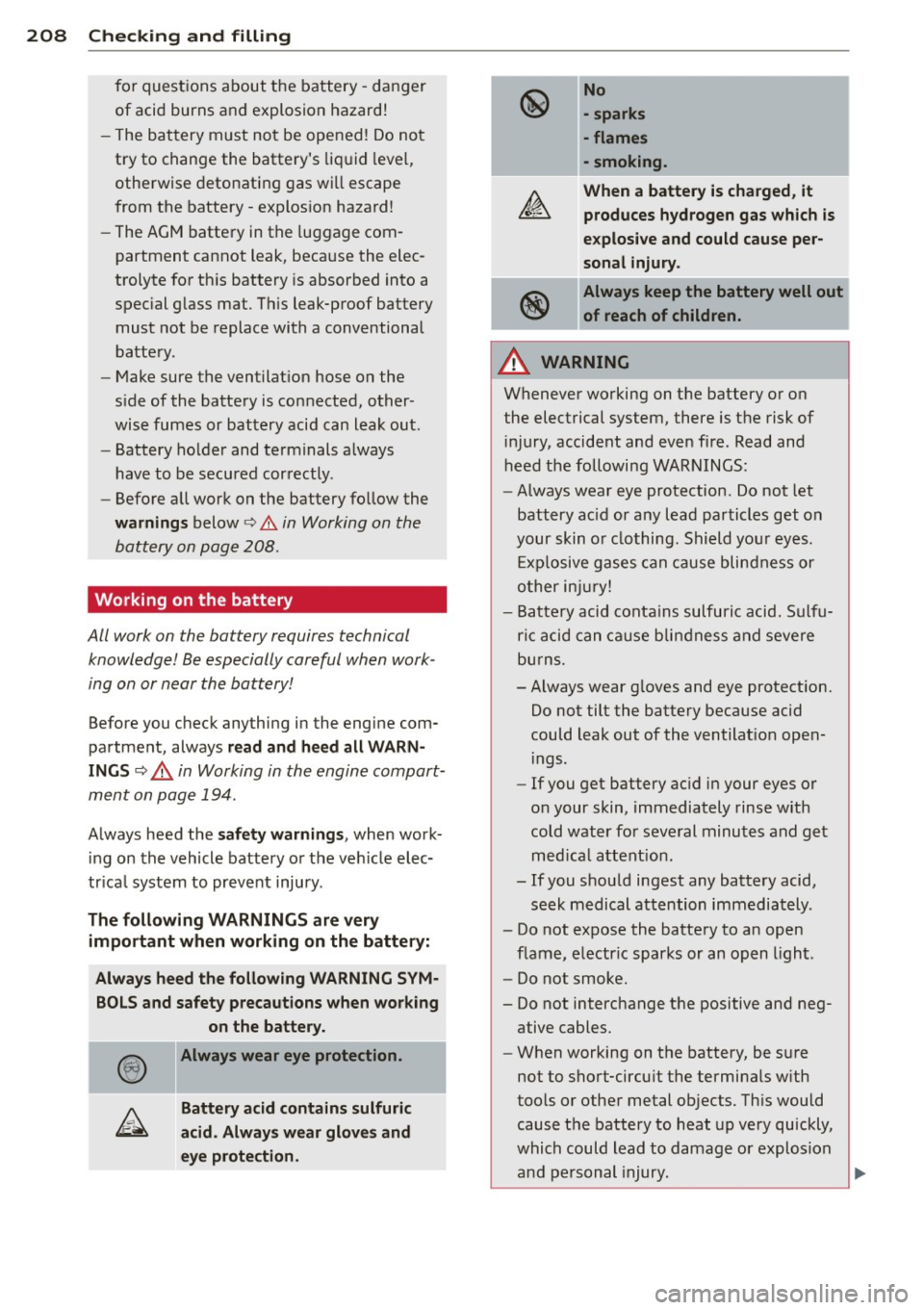
Always heed the following WARNING SYM ·
BOLS and safety precautions when working on the battery.
Always wear eye protection.
Battery acid contains sulfuric
acid . Always wear glove s and
eye prote ction . No
• sparks
• flames
- smoking.
When a battery is charged , it
produces hydrogen gas which is
e x plosive and cou ld cause per
sonal injury .
®
Always keep the battery well out
of reach of children.
A WARNING ,___
Whenever working on the battery or on
the electrical system, there is the risk of
i njury, accident and even fire . Read and
heed the following WARNINGS :
- Always wear eye protection . Do not let
battery ac id or any lead particles get on
your skin o r clothing . Shield you r eyes.
Exp losive gases can cause blindness or
o ther inju ry!
- Battery acid conta ins sulfuric acid. Sulfu
ric acid can ca use blindness and severe
bu rns.
-Always wear g loves and eye protection.
Do not tilt the battery because acid
could leak out of the ventilat ion open
ings .
- If you get battery ac id in your eyes or
on your skin, immediately rinse with
cold water for several minutes and get med ica l attent ion .
- If you shou ld ingest any battery acid,
seek medical attention immediately .
- Do not expose the batte ry to an open
flame, electr ic sparks or an open l ight.
- Do not smoke.
- Do not interchange the positive and neg-
ative cables.
- When working on the battery, be s ure
not to short-circu it the terminals w ith
too ls or othe r metal objects. Th is would
cause the battery to heat up very quickly,
which could lead to damage or explosion
-
and pe rsonal injury . ~
Page 211 of 280

-When a battery is charged, it produces
hydrogen gas which is explosive and
could cause personal injury.
- Always keep the battery well out of the
reach of children.
- Before work is done on the electrical sys
tem, disconnect the negative ground ca
ble.
- Before performing any work on the elec
trical system, switch off the engine and
ignition as well as any electrical equip
ment. The negative cable on the battery
must be disconnected. If you are just go
ing to replace a light bulb, then it is
enough to switch off the lights.
- Before disconnecting the battery, switch
off the anti-theft alarm system! Other
wise you will set off the alarm.
- When disconnecting the battery, first
disconnect the negative cable and then
the positive cable.
- Before reconnecting the battery, make
sure all electrical consumers are switch
ed off. Reconnect the positive cable first
and then the negative cable. Never inter
change the cables -this could start a fire!
- Never charge a frozen or a thawed-out
battery. It could explode! If a battery has
frozen, then it must be replaced. A dis
charged battery can freeze over at
32 °F
(0 oc).
-Mak e sure the vent hose is always attach
ed to the opening on the side of the bat
tery.
- Never use batteries which are damaged.
There is the danger of an explosion! Al
ways replace a damaged battery.
_& WARNING
California Proposition 65 Warning:
- Battery posts, terminals and related ac cessories contain lead and lead com
pounds, chemicals known to the State of
California to cause cancer and reproduc
tive problems. Wash hands after han dling.
Checking and filling 209
(D Note
- Do not disconnect the vehicle battery
when the ignition is switched on or when
the engine is running, otherwise, you will
damage electronic components in the
electrical system.
- When working on the engine, protect the
battery housing from ultraviolet (UV)
rays by not parking the vehicle in direct
sunlight .
- If your vehicle is going to stand for a
long period of time without being driven,
protect the battery from "freezing", oth
erwise it will be damaged and will then
have to be replaced
~ page 209.
Charging of battery
All work on the battery requires technical knowledge!
Fig. 165 E ngine compart ment: conne ctors for a charg
er and jump start cables
A charged battery ensures good starting per
formance . A discharged battery can
freeze at
temperatures of only
O 0C. A frozen or thawed
battery must be replaced, as the battery
housing may be cracked due to freezing and
could therefore leak acid.
.,. Always read and heed all WARNINGS be
low~ .&, and ~.&, in
Working on the bat
tery on page 208.
... Switch off the ignition and all electrical con
sumers .
.,. Make sure the area is well ventilated when
you charge the battery.
.,. Connect charger cables.
Charger cables
must always be connected POSITIVE
G to ..,.
Page 212 of 280
![AUDI A3 2012 Owner´s Manual 210 Check ing and filling
POS IT IVE E] and NEGATI VE [:] to NEGATIVE
(j ump sta rt pins)[:].
.. Switch on the charger.
• Make sure the charging rate is not over
6 amps.
� AUDI A3 2012 Owner´s Manual 210 Check ing and filling
POS IT IVE E] and NEGATI VE [:] to NEGATIVE
(j ump sta rt pins)[:].
.. Switch on the charger.
• Make sure the charging rate is not over
6 amps.
�](/img/6/40267/w960_40267-211.png)
210 Check ing and filling
POS IT IVE E] and NEGATI VE [:] to NEGATIVE
(j ump sta rt pins)[:].
.. Switch on the charger.
• Make sure the charging rate is not over
6 amps.
• Turn off the charger¢,&..
• Disconnect the charger cables.
• Connect both battery cables to the battery
i f necessary -
first plus, then minus.
The battery must not be opened!
¢ @ in Gen
eral information on page 207 .
Chargi ng the b attery
Only use chargers with a m ax im um cha rg in g
v oltage o f
14.8 V. The battery connecting ca
bles do not need to be disconnected. Do not
open the battery when charging.
Read all of the manufacturer's instructions for
the charger before charting the battery.
It is not necessary to remove the battery from
the engine compartment, and it is a lso not
necessary to disconnect the cables.
Normally, a battery should be charged at no
more than 10 percent of its rated capacity.
For example, a charging current of 4.5 amps
wo uld be used on a battery rated at 45 Ah.
Rated capacity of the battery in your veh icle is
listed on the battery housing .
The battery caps shou ld
not be opened when
cha rg ing a battery.
_& WARNING
Cha rging a battery can be dangerous.
- Never charge a frozen battery. It may ex
plode because of gas trapped in the ice .
Allow a frozen battery to thaw o ut first .
- Do not reuse batteries which we re fro
zen. They must be replaced. The battery
housing may have cracked and weakened
when the battery froze.
- Charge the battery in a we ll ventilated
area. Keep away from open f lame or elec
trical spark. Do not smoke. Hydrogen gas generated by the battery is explosive. -
To reduce the danger of exp losion, never
connect or d isconnect charger cab les
while the charger is operating.
- Fast charging a battery is dangerous and
should only be attempted by a compe
tent techn ic ian with the proper equip
ment.
- Battery acid that may sp ill dur ing charg
ing should be washed off with a solut ion
of warm water and baking soda to neu
tralize the ac id.
{[) Note
-Make sure that the gas venting hose is
always connected to the or iginal opening
on the battery s ide. Otherwise gasses or
battery acid could leak out.
- Never use a fast charger as a booster to start the engine. This will seriously dam
age sensitive electron ic components,
such as contro l units, re lays, radio, etc.,
as well as the batte ry charger.
- T he vehicle may be optionally equ ipped
w ith a gel battery, wh ich can only be
charged at a cons tant current-lim ited
voltage . To prevent damage to the bat
tery and the electronics system, a gel battery that is connected must under no
circumstances be charged with a quick
charger.
{!) Tips
- The vehicle battery must not be charged
with a standard small charger that pl ugs
into the outlet.
- Only charge the battery through the con
nections in the engine compartment.
Battery replacement
The new battery must hove the some specifi
cations as the old one.
Intelligent energy management in your vehi
cle is responsible for distributing the electri
ca l energy throughout your vehicle
¢
page 167. The intelligent energy manage-
ment system will keep the engine battery .,..
Page 213 of 280
charged better then vehicles without this sys
tem . To make sure the additional e lectrica l en
ergy is available once again after you have
changed the battery, we recommend that you install batteries of the same type and manu
facture only (the same as those installed at
the t ime your vehicle was delivered). Specifi
cations are listed on the battery hous ing . Your
authorized dealer must code the battery in
the energy management system to enable yo u
to use the energy management functions cor
rectly after replacing the bat tery.
If it is not possible to use a battery of this
type, the new battery must have the same ca
pacity, voltage (12 volts) , amperage, con
struction and plug sealing.
We re commend that you use ma intenance
free or
cy cle -re sis tant /le ak-proof batteries
that conform to the standards TL
825 06
(from December 1997) and VW 7 SO 73 (from
Aug ust 2001).
When insta lling the bat tery , make sure the ig
n ition and all e lectrica l consumers are turned
off .
CD Note
-Make sure tha t the gas venting hose is
always connected to the o riginal open ing
on the battery side . Otherwise gasses or
battery acid could leak out.
- Battery mounts and clamps m ust always
be secured correctly.
- Read and follow the warnings under
C? page 208, Working on the battery be
fore performing any work on the battery .
@ For the sake of the environment
Because of the problem of proper d isposa l
o f a battery, we recommend your author
ized Audi dealer change the batte ry for
you. Batteries contain su lfuric ac id and
lead and must always be disposed of prop
erly in compliance w ith all environmental
regu lations . D isposing of vehicle batte ries
improperly is very dangerous to the envi
ronment. Make sure that the removed bat-
Checkin g and fillin g 211
tery cannot overbalance, otherwise su lfu
ric acid might escape!
Windshield washer container
Using plain water is not adequate for filling
the $ windshield washer system .
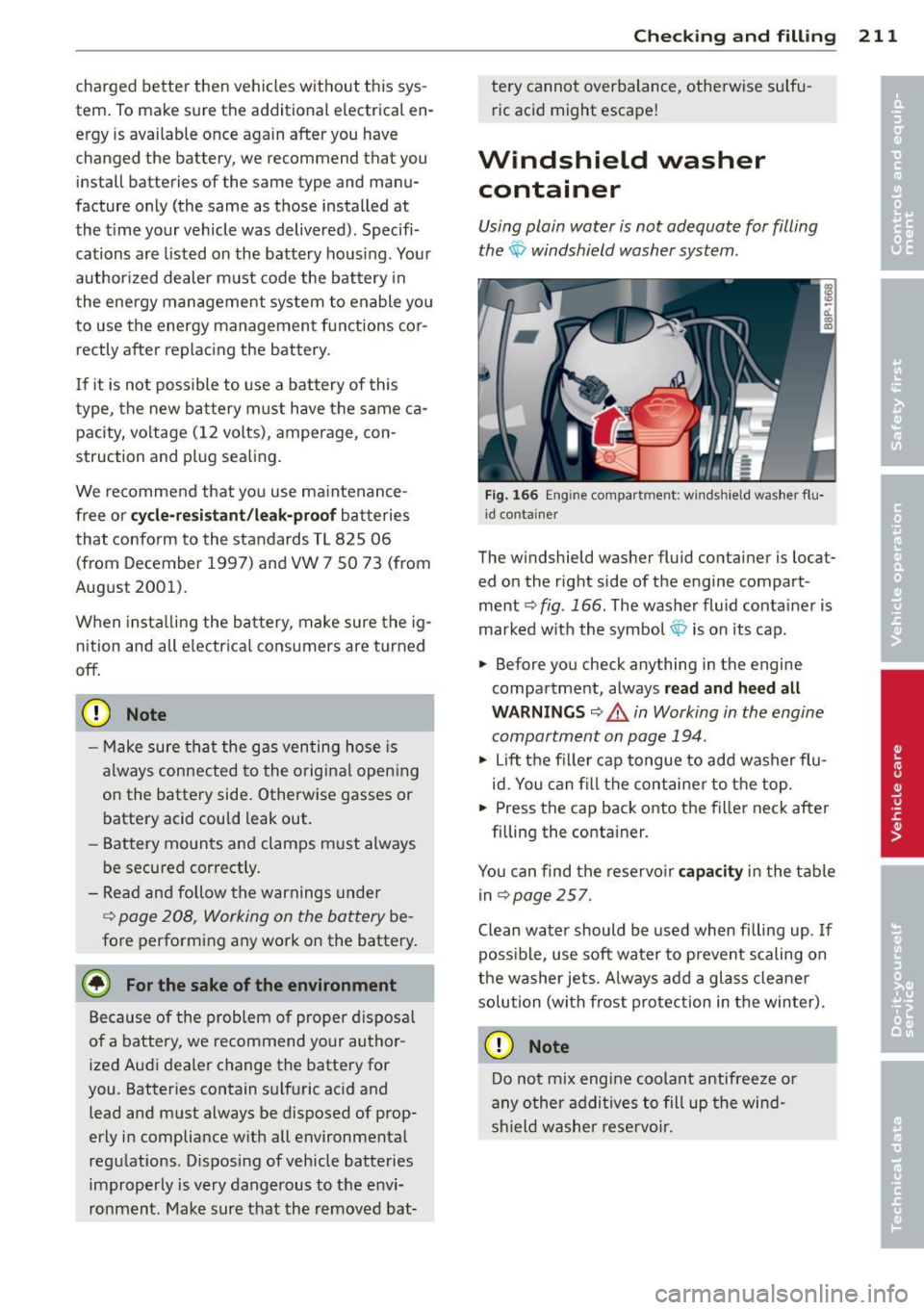
Fig. 166 En gin e compart men t: w in ds hield washer flu
i d co ntai ner
The windshield washer fluid container is locat
ed on the right side of the engine compart
ment ~
fig. 166. The washer fluid conta iner is
marked w ith the symbol $ is on its cap .
.,. Before you check anything in the engine
compartment, always
read and heed all
W ARNINGS ~ _&. in Working in the engine
compartment on page 194.
.,. Lift the fil le r ca p tongue to add washer flu
id. You can fi ll the container to the top.
.,. Press the cap back onto the f iller neck after
f illing the container .
You can find the reservo ir
capacity in t he t able
in
C? page 257.
Clean water should be used when filling up . If
poss ible, use soft water to prevent scaling on
the washer jets. Always add a glass cleane r
solu tion (with frost protection in t he win ter).
CD Note
Do not mix engi ne coolant antifreeze o r
a ny o ther addi tives to fill up the wind
sh ield washer rese rvoi r.
Page 238 of 280
236 What do I do now?
-After installing the compact spare wheel,
the tire inflation pressure should be
checked and, if necessary, increased to
60 psi (4.2 bar).
- The load carrying capacity is marked on
the tire sidewalls and must not be ex
ceeded.
- After installing the compact spare wheel,
make sure that you remount the flat tire
in its storage area properly.
- The compact spare tire should be proper
ly remounted in its storage area as soon
as the standard road tire can be re placed .
- Because the compact spare tire was spe
cifically designed for your vehicle, it must not be used on any other vehicle .
Likewise, compact spare wheels from
other vehicles must not be used on your
vehicle.
- The compact spare tire must not be
mounted on any other wheels, nor must
standard tires, snow tires, wheel covers
or trim rings be used with the compact
spare wheel. If such use is attempted,
damage to these items or other vehicle
components may occur .
(D Tips
Check the inflation pressure of the com
pact spare tire (60 psi/4.2 bar) periodically
to keep the tire ready for use.
Wheel change
Before changing a wheel
Observe the following precautions for your
own and your passenger's safety when chang
ing a wheel .
.. After you experience a tire failure, pull the
car well away from moving traffic and try to
reach
level ground before you stop c:> ,&. .
.. All passengers should leave the car and
move to a safe location (for instance, behind
the guardrail)
c:> _&. .
.. Apply the parking brake firmly c:> _&. .
.. Move selector lever to position Pon an au
tomatic transmission ; put manual transmis
sion in
first gear c:> _&..
.. If you are towing a trailer : unhitch the trail
e r from your vehicle.
.. Take the
tool and the spare tire c:> page 234
out of the luggage compartment .
.&, WARNING
You or your passengers could be injured
while changing a wheel if you do not fol
low these safety precautions:
- If you have a flat tire, move a safe dis
tance off the road. Turn off the engine,
turn the emergency flasher on and use
other warning devices to alert other mo
torists.
- Make sure that passengers wait in a safe place away from the vehicle and well
away from the roadway and traffic .
- To help prevent the vehicle from moving suddenly and possibly slipping off the
jack, always fully set the parking brake
and block the wheel diagonally opposite
the wheel being changed. When one
front wheel is lifted off the ground, plac
ing the automatic transmission in "P"
(Park) , or engaging a gear in a manual
transmission will
not prevent the vehicle
from moving.
- Before you change a wheel, be sure the
ground is level and firm. If necessary,
use a sturdy board under the jack.
- After installing the spare wheel, make
sure that you remount the flat tire/wheel
in its storage area properly and tighten
the knurled retaining screw securely.
Changing a wheel
-
When you change a wheel, follow these
quence described below step-by-step and ex
actly in that order .
1. Remove the decorative wheel cover*. For
more details see also
c:> page 23 7, Deco
rative wheel covers
or c:> page 238,
Wheels with cap-covered wheel bolts.
Page 245 of 280
Fuses and bulbs
Electrical fuses
Replacing fuses
A problem in the electrical system may be caused by a blown fuse .
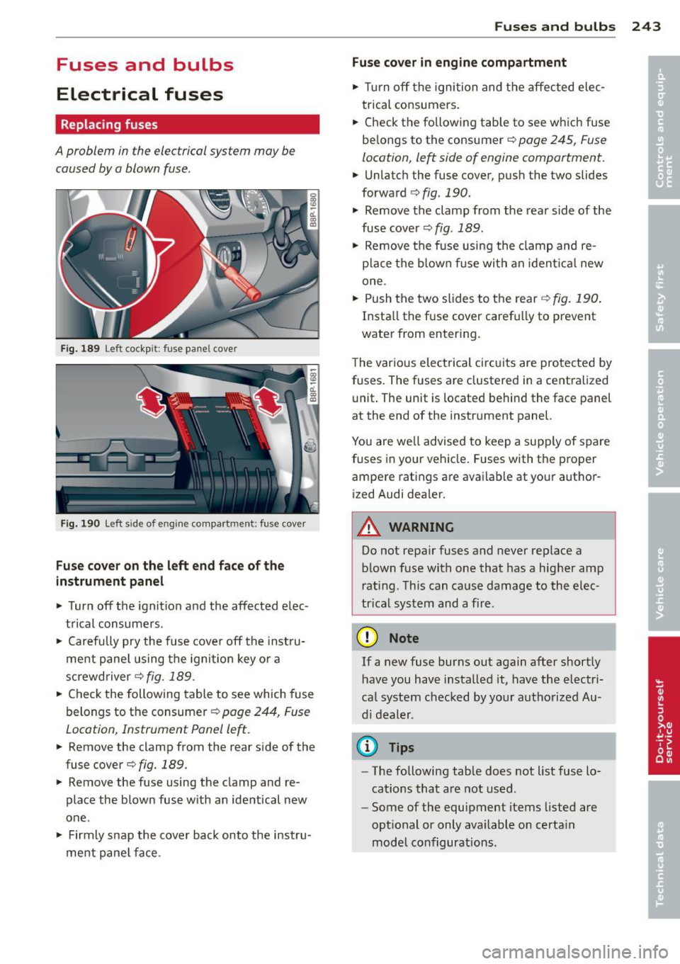
Fig. 189 Left cockpit: fuse pane l cover
Fig. 190 Left side of eng ine compartment: fuse cover
Fuse cover on the left end face of the
instrument panel
.. Turn off the ignition and the affected elec
trical consumers .
.. Carefully pry the fuse cover off the instru
ment panel using the ignit ion key or a
screwdriver
c;> fig. 189 .
.. Check the following table to see which fuse
belongs to the consumer
c;> page 244, Fuse
Location, Instrument Panel left.
.. Remove the clamp from the rear side of the
fuse cover ¢
fig. 189.
.. Remove the fuse using the clamp and re
place the blown fuse w ith an identical new
one.
• Firmly snap the cover back onto the instru
ment panel face .
Fuses and bulbs 243
Fuse cover in engine compartment
.. Tur n off the ignition and the affected elec
trical consumers .
.. Check the following tab le to see which fuse
be longs to the consumer
c;> page 245, Fuse
location, left side of engine comportment .
.. Unlatch the fuse cover, push the two slides
forward ¢
fig. 190.
• Remove the clamp from the rear side of the
fuse cover
c;> fig . 189.
• Remove the fuse using the clamp and re
place the blown fus e with an ident ical new
one .
.. Push the two slides to the rear¢
fig. 190.
Insta ll the f use cover caref ully to prevent
water from entering.
T he var ious electrical circ uits are protected by
fuses. The fuses are clustered in a centralized
unit. The unit is located behind the face panel
at the end of the instrument panel.
You are well advised to keep a supply of spare
fuses in your vehicle . Fuses with the proper
ampere rat ings are avai lab le at your author
ized Audi dealer.
_& WARNING
= -
Do not repair fuses and never replace a
blown fuse with one that has a higher amp
rating. This can cause damage to the elec
trical system and a fire .
(D Note
If a new fuse burns out again after shortly
have you have installed it, have the electri
ca l system checked by your authorized Au
di dealer .
(D Tips
-The following table does not list fuse lo
cat ions that are not used .
- Some of the equipment items listed are
optional or only available on certain
model configurations.
Page 247 of 280
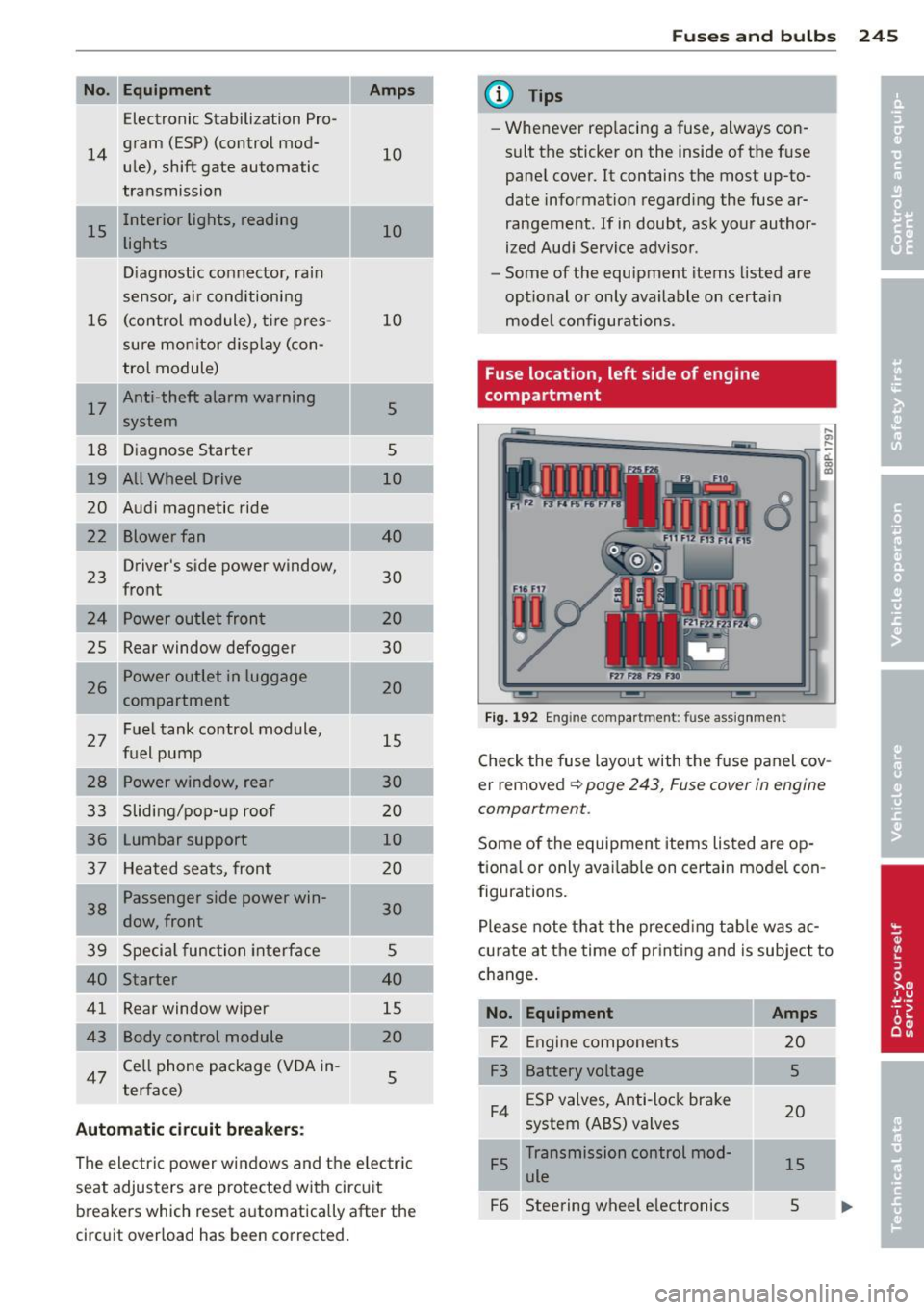
No. Equ ipment
Electronic Stabilization Pro-
14
gram (ESP) (control mod-
u le), shift gate automatic
transmission
15 Interior lights, reading
lights
Diagnostic connector, rain
sensor, air conditioning
16 (control module), t
ire pres-
sure monitor d isplay (con-
trol module)
I 17
Anti-theft alarm warning
system
18 D iagnose Starter
19 All Wheel D rive
20 Audi magnetic ride
Blower fan
23
Driver's
side power window,
front
24 Power outlet front
2S Rear window defogger
26 Power outlet in luggage
compartment
27 Fuel tank control module,
fuel pump
28 Power window, rear
33 Slidi ng/pop-up roof
36 Lumbar support
37 Heated sea ts, front
1 38
Passenger side power win-
dow, front
39 Specia l func tion interface
40 Starter
41 Rear window wiper
43 Body control module
47
Ce ll phone package (V OA in-
terface)
Automatic circuit breakers:
10
10
10
5
5
10
40
30
20
30
20
15
30
20 10
20
30
5
40
15
20 5
The electri c power w in dows and the e lectr ic
seat adjusters are pro tected with circu it
breake rs which reset automatically after the
circuit overload has been corrected.
Fu se s and bulb s 245
@ Tips
-Whenever rep lacing a fuse, always con
sult the sticker on the inside of the f use
pane l cover. It contains the most up-to
date information regarding the fuse ar
rangement. If in doubt, ask your author
ized Aud i Service adviso r.
- Some of the equipment items listed are
opt ional or only available on certa in
mode l configurations.
Fuse location, left side of engine
compartment
Fig . 192 En gine compar tment : fuse assig nment
,._
-d. a, a>
Check the fuse layout with the f use panel cov
er removed
¢ page 243, Fuse cover in engine
comportment.
Some of the equipmen t items listed are op
tiona l or only ava ilab le on certain model con
figurations.
Please note tha t the preced ing tab le was ac
c u rate at the time of pr int ing and is subject to
c h ange.
No. Equipment
F2 Engine compone nts
F3 Battery voltage ESP valves, Anti-lock brake
F4 system (ABS) valves
Transmission control mod
F5 ule
F6 Steering wheel e lectronics
Amps
20
5
20
15
s
Page 250 of 280
248 Emergency situations
Emergency situations
General
This chapter is intended for trained emer
gency crews and working per sonnel who
have the necessary tools and equ ipment to
perform these ope rations.
Starting by pushing or
towing
Q;) Note
Vehicle s with an automati c transmission
cannot be started by pushing or towing .
Starting with jumper
cables
Jumper cable: Note the manufacturer's infor
mation.
If th e battery is d ischa rged, another vehicle
can provide starting assistance. For this you
req uire a j umper cab le . Both batteries m ust
have the same voltage (V) and a s imilar ca
pac ity (Ah).
Jumper cables
Use only jumper cab les of sufficiently
large cross section to safely carry the sta rter
cur rent. Refer to the manufacturer 's specifica
ti ons.
Use on ly jumper cables with
isola ted termina l
clamps an d properly marke d for distinction :
plus(+) cable in most cases colo red red
minu s(-) cable
in most cases colo red black .
The wire cross section must be at least
0.038 in
2 (25 mm2 ) for gasoline eng ines and
at least 0.054 in
2 (35 mm2
) for diese l en
gines .
A WARNING
Batte ries co ntain e lec tricity, ac id, a nd gas .
Any of these can cause ve ry ser io us or fatal i
njury . Follow the instructions below for
safe handling o f your vehicle's battery.
- Always shie ld your eyes and avo id lean-
ing over the battery wheneve r poss ib le.
- A discharged battery can a lready freeze
at temperatures just be low 32 °F (0 °() .
N ever attempt to provide start ing ass is
tance on a frozen or thawed out batte ry -
Da nger of explosion and chemical burns!
Replace a battery if it has bee n froze n.
- Do not allow battery acid to contact eyes
or skin . Fl ush a ny con tacted a rea with
wa te r immediat ely .
- Imp rope r use of a booster battery to
start a vehicle may cause an ex plosion .
- Vehicle batter ies ge nerate explosive gas
e s . K eep spar ks, flame and lighted c iga
r e ttes away from ba tteries.
- Do not try to ju mp start a ny ve hicle w it h
a low ac id leve l in the battery .
- The vo ltage of the bo oste r batte ry m ust
a lso have a 12-Vo lt rat ing. T he capacity
(A h) of the booste r battery sho uld not b e
lowe r than that of the discharged bat
tery . U se o f batte rie s of d iffe ren t voltage
or subs tan tia lly diffe ren t "Ah" rat ing
may c ause an exp losion and person al in
jury .
- N ever ch arge a fr oze n b atte ry. Gas t rap
ped in the i ce may c ause an ex plosion .
- N ever ch arge or use a batt ery th at h as
been frozen . T he battery case may have
be weake ned.
- Us e of batt erie s of diff ere nt vol tage or
subs tanti ally diff eren t ca pac ity (Ah) rat
in g may cause an exp losion and injury.
The ca pac ity ( Ah) of the booster battery
should not be lower than that of the dis
charged batte ry.
- Before you check anythin g in the engine
compa rtment, always read and heed a ll
WAR NIN GS¢
page 187, Engine com
partment.
Page 252 of 280

250 Emergency sit uat ions
2. Otherwise apply the hand brake and shift
into idle gear if your vehicle has manua l
transmission, and put the selector lever
into P position if your vehicle has auto
matic transmission.
3 . For both vehicles switch off all consumers
and the ig nition .
Connectin g/disco nn ecting th e jumper
cable
4 . Connect one end of the red jumper cable
to the positive term inal
(D ¢ fig . 193 of
the discharged battery @ ¢0
in General
information of starting assistance on
page 249 .
5. Connect the other end of the red jumper
cab le to the positive termina l@ of the
booster battery @.
6 . Connect one end of the black jumper ca
b le, preferably at the ground point. Other
wise, connect it to the negative terminal
@ of the booster battery @.
7 . Connect the other end of the black jumper
cab le to the
ground po int (bolt head )©
in your v ehi cle @ .
8. Route the jumper cables so that they can
not catch in any rotating parts in the en
gine compartment.
Starting the engine
9 . Start the engine of the vehicle provid ing
assistance and allow it to run at idle .
10. Now start the eng ine o f the vehicle w ith
the discharged battery, wa it for two to
three minutes unti l the engine "runs"
smoothly .
11. If the engine does not start: Stop trying
after
10 seconds and then try again after
about
30 seconds.
12 . In the veh icle that has received start as
sistance, turn on the heater blower and
the rea r window heat ing to eliminate any
voltage peaks when disconnecting. Driv
ing lights must be swi tched off!
13. Disconnect the cable whi le the engine is
running exact ly in
reverse order to that
described in¢
page 250, Connecting/dis
connecting the jumper cable.
When do ing so, make sure that the cable cannot con
tact rotating engine parts.
14. Turn the heater b lower and the rear w in-
dow heating off again .
The battery is vented to the outside to prevent gases from entering the vehicle interior .
Make sure that the jumper clamps are we ll
connected with thei r
metal ports in full con
tact
with the battery terminals .
A WARNING
To avoid serious personal injury and dam
age to the vehicle, heed all warnings and
instructions of the jumper cable manufac
turer. If in doubt, call for road service.
- Jumper cables must be long enough so
that the veh icles do not touch.
- When connecting jumper cables, make sure that they cannot get caught in any
mov ing parts in the engine compart
ment.
- Before you check anything in the engine
compartment, always read and heed all
WARNINGS ¢page 187, Engine com
partment.
{CT) Note
Improperly connected jumper cab les can
damage or destroy the generator .
- Do not use the battery negative terminal
for jump start ing or a malfunct ion could
occur in the vehicle electrical system.
- Always connect POSITIVE(+) to POSI-
TIVE(+), and NEGATIVE(-) to NEGATIVE
( - ) term inal.
- Check that all screw p lugs on the battery
cells are screwed in firm ly . If not, tighten
plugs prior to connecting clamp on nega
tive batte ry term inal.
- Please note that the procedure for con
necting a jumper cable as described
above applies specifically to t he case of
your vehicle being jump st arted. When
yo u are g iving a jump sta rt to another ve
hicle, do
not connect the minus( -) cable
to the minus (-) terminal on the dis
charged battery@¢fig.193 . Instead,
Page 255 of 280

-The vehicle should never be lifted or jacked
up from underneath the engine oil pan , the
transmission housing , the front or rear
a x le or the body side members. This could
lead to ser ious damage.
- Use lifting equipment with padded contact
surfaces to avo id damage to the underbody
or chassis frame.
- Alternatively, cover the contact surfaces on
workshop hoist or floor jack w ith rubber
pads b efore lifting.
- Before dri ving over a workshop hoist, check
that the vehicle weight does not exceed the
permissible lifting capacity of the hoist .
- Before dr iving over a workshop hoist, en
sure that there is sufficient clearance be
tween the hoist and low parts of the vehi
cle .
A WARNING
To r educe the ris k of seriou s injury a nd ve
hicle da mage:
- Always lift the veh icle only at the spec ial
wor ks ho p hoi st and floor j ack lift p oin ts
ill ustra te d
c:;>page 253, fig. 199 and
c:;>page 253, fig . 20 0.
- F ailure to l ift the vehicl e at th ese poi nts
cou ld ca use the ve hicle to t ilt or fall from
a lift if there is a c ha nge in vehicle wei ght
dist rib ution and balance . This might hap
pen, for example, when heavy c ompo
nents such as the e ngine bloc k or t rans
mission are removed.
- W hen remov ing s uch heavy c omponents,
anchor veh icle to h oist or add corre
sponding we ights t o maintain the center
of g rav ity. Oth erwise, th e veh icle m ig ht
t il t o r slip off the hois t, causing serio us
p ers onal in ju ry.
Emergency situations 253
Lifting with workshop hoist and with
floor jack
T he vehicle may only be lifted at the li~ing
p oi nt s illus tra ted.
..,
---------~1::
Fig. 199 Front lifting point
Fig. 200 Rear lifting point
.,. Read and heed WAR NIN G c:;> &. in Impor
tant safety precautions on page 253 .
.,. Locate lifting points c:;> fig. 199 c:;> fig . 200 .
.,. Adjust lifting arms of workshop hoist or
fl oor jack to matc h ve hicle lift ing poi nts.
I
.,. Insert a rubbe r pad between the floo r jac k/
workshop hoist and t he lift ing poin ts .
If you must l ift your vehicle with a floor jack
to work underneath, be sure the vehicle is
safely supported on stands intended for this purpo se .
Front lifting point
The lifting poi nt is located o n the floo r pan re
inforcement about at the same leve l as the
jac k mounti ng po int
c:;> fig. 199. Do not lift
the vehicle at the vertical sill reinforcement .
Rear lifting point
The liftin g point is located on the vert ica l rein
forcement of the lower s ill for the on board
jack
c:;> fig. 200. ..,.