lamp AUDI A3 2015 Owners Manual
[x] Cancel search | Manufacturer: AUDI, Model Year: 2015, Model line: A3, Model: AUDI A3 2015Pages: 288, PDF Size: 71.46 MB
Page 25 of 288
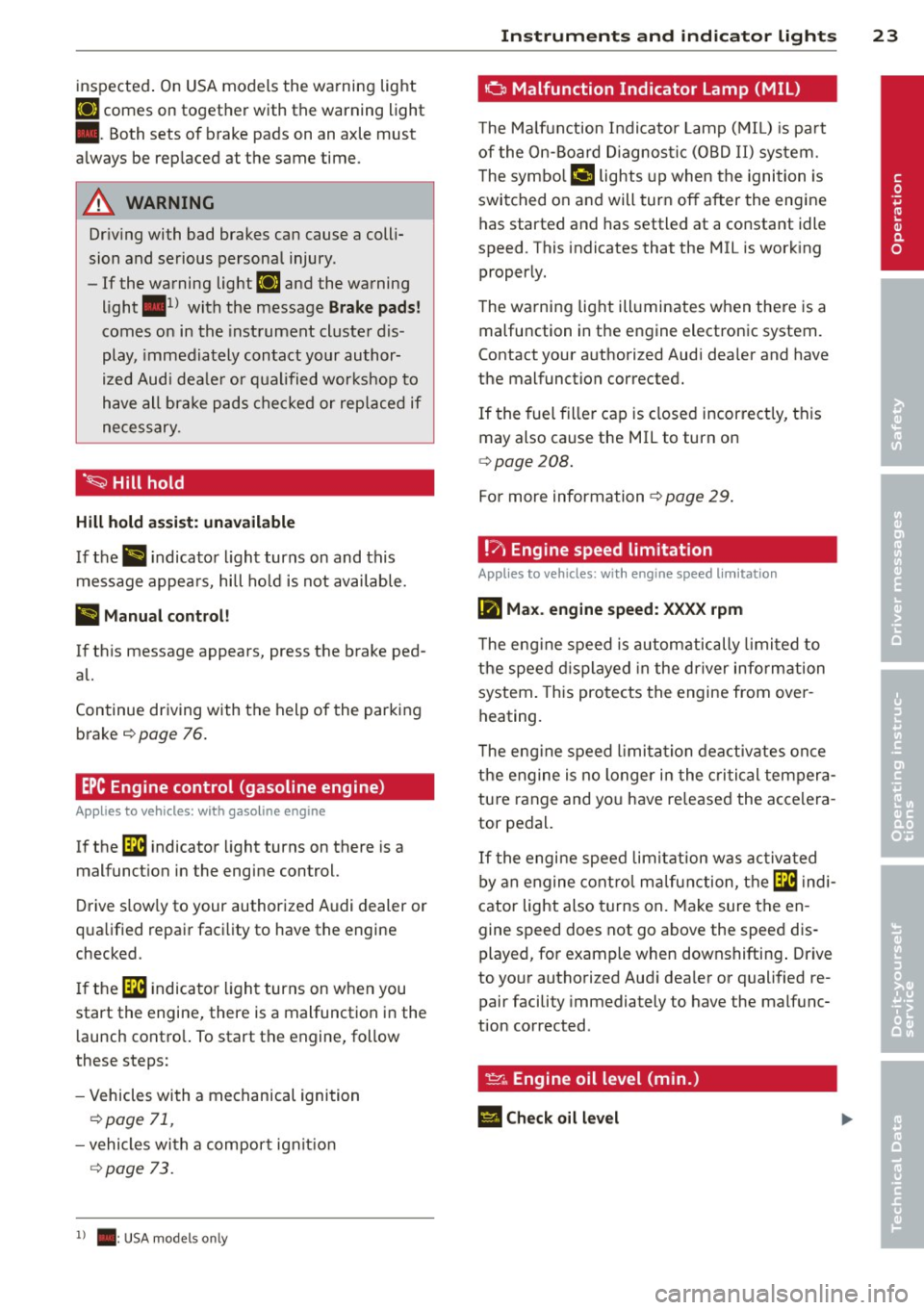
inspected. On USA models the warning light
[IJ comes on together with the warning light
• . Both sets of brake pads on an axle must
always be rep laced at the same time.
_& WARNING
Dr iv ing with bad brakes can cause a coll i
sion and serious personal injury.
- If the warning light
[IJ and the warning
light
. l) with the message Brake pads!
comes o n in the instrument cluste r dis
play, immed iately contact your au thor
i z ed Audi dea le r or q ualified wor kshop to
have all bra ke p ad s ch ecked or rep laced if
necessary.
· ~ Hill hold
Hill hold a ssis t: un available
If th e> #j •ndicato r light turns on and this
message appea rs, hill ho ld is not available.
II Manual control!
If this message appears, press the b rake ped·
al.
Continue driving w ith the help of the parking
brake ¢
page 76.
EPC Engine control (gasoline engine)
Applies to vehicles: with gasoline engine
If the ~ indicator light turns on there is a
malfunct ion in the engine control.
D rive s low ly to your authorized Audi dealer or
q ua lified repair faci lity to have the engine
checked .
I f the ~ indica to r li ght turns on when you
start the engine, there is a malfunction in the
l aunch contro l. To start the engine, follow
these steps:
- Vehicles wi th a mechanical ignition
¢ page 71 ,
-vehicles wi th a compor t igni tion
c:> page 73.
1) . : USA mode ls onl y
Instrument s and indicator ligh ts 23
o Malfunction Indicator Lamp (MIL)
The Ma lfun ction Indi cato r Lamp ( MIL) is pa rt
of the On-Board Diagnos tic (OBD II) sys tem.
T he sym bo l
('4 lights up when the ignition is
switched on and will tur n off after the engine
has started and has settled at a constant idle
speed . This indicates that the MIL is work ing
properly.
T he wa rning lig ht ill uminates when the re is a
malfunction in the engine electronic system .
Contact your a uthorized Aud i dea ler and have
the malfunction corrected.
If the fuel fille r cap is closed incor rect ly, this
may also cause the MIL to turn on
c:> poge 208.
For more information ¢ page 29 .
!7, Engine speed limitation
Applies to vehicles: wi th engine speed lim itatio n
(m Max. engine speed: XXXX rpm
T he eng ine speed is automatically limi ted to
the speed displayed in the driver info rm ation
system . This pro te cts the engine from over
heating.
T he eng ine speed l imi ta tion dea ctivates on ce
the engine is no longer in the cri tical tempera
tu re range and yo u have re lease d the acce lera
tor pedal.
If t he engine speed limi tat ion was act iva ted
b y an engine cont rol m alfunc tio n, the ~ indi
cator light also turns on. Make sure the en
gine speed does not go above the speed dis
played, fo r example when downshifting . Drive
to yo ur authorized Aud i dea le r or qualified re
pair facility immediately to have the malfunc
tion corrected .
~. Engine oil level (min.)
El Check oil level
•
Page 26 of 288
24 Instruments and indicator lights
You may continue driving for the time being .
Check the oil level as soon as possible
¢ page 212.
-If the engine oil level is too low, add engine
oi l
¢ page 215.
-If the engine oil level is correct and the indi
cator light still turns on, drive at low engine
speed to the nearest authorized Audi dea ler
or qualified repair facility.
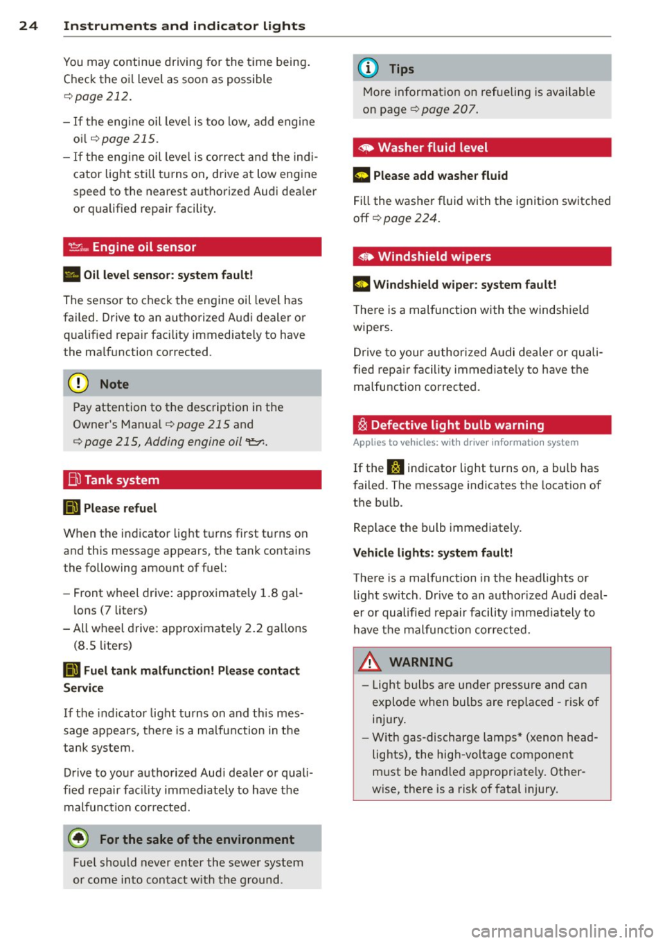
_..,. Engine oil sensor
II Oil level sensor: system fault!
The sensor to check the engine oil level has
failed. Drive to an authorized Audi dealer or
qua lified repair faci lity immediately to have
the malfunction corrected.
Q;) Note
Pay attention to the description in the
Owner 's Manual
¢ page 215 and
¢ page 215, Adding engine oil "l::;1:.
Bil Tank system
RD Please refuel
When the indicator light turns first turns on
and this message appears, the tank contains
the following amount of fuel:
- Front wheel drive : approximately 1.8 gal
lons (7 liters)
- All wheel drive: approximately 2.2 gallons
(8 .5 liters)
RD Fuel tank malfunction! Please contact
Service
If the indicator light turns on and this mes
sage appears, there is a ma lfunction in the
tank system.
Drive to your authorized Aud i dealer or quali
fied repair facility immediately to have the
malfunction corrected.
@) For the sake of the environment
Fuel should never enter the sewer system
or come into contact w ith the ground.
(D Tips
More information on refueling is available
on page ¢
page 207.
~ Washer fluid level
m Please add washer fluid
Fill the washer fluid with the ignition switched
off ¢
page 224.
• Windshield wipers
m Windshield wiper: system fault!
There is a malfunction with the windshie ld
wipers .
Drive to your authorized Audi dealer or quali
fied repair facility immediate ly to have the
malfunction corrected.
~ Defective light bulb warning
Applies to vehicles: wit h drive r info rmatio n system
If the S:i indicator light turns on, a bulb has
failed. The message ind icates the location of
the bulb .
Replace the bulb immediately.
Vehicle lights: system fault!
There is a malfunction in the headlights or
light switch. Drive to an author ized Audi deal
er or qualified repair facility immediately to
have the malfunction corrected.
_&. WARNING
- Light bulbs are under pressure and can
explode when bu lbs are replaced -risk of
inj ury.
- With gas-discharge lamps* (xenon head
lights), the high -voltage component
must be hand led appropriate ly. Other
wise, there is a risk of fatal injury.
-
Page 31 of 288
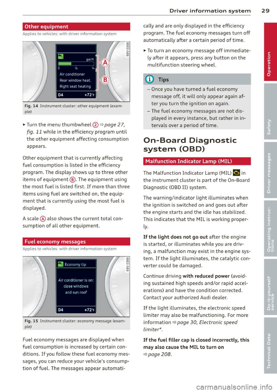
Other equipment
Applies to vehicles: with driver information system
Fig. 1 4 Instrument cluste r: other e quipmen t (e xam
p le)
~ Turn the menu thumbwheel@¢page 27,
fig. 11 while in the efficiency program until
t h e other eq uipme nt affect ing consump tion
appears .
Other equipmen t that is curren tly affecting
fuel cons umption is listed in t he eff iciency
p rog ram. The display shows up to three other
items of equipment @. The equipment using
the most f uel is listed first . If more than thr ee
items us ing fue l are switched on, the equip
ment that is cu rrently using the most fuel is
d isplayed .
A scale @ also shows the current total con
sumpt ion of all other equipment .
Fuel economy messages
Applies to vehicles: with driver information system
Fi g. 15 Instrum ent clus ter: e conomy m essa ge (e xam
p le)
Fue l economy messages are displayed when
fuel consumption is increased by certain con
d itions .
If you follow these fuel economy mes
sages, you can reduce your vehicle's cons ump
tion of fuel. The messages appear automati-
Dr iver in formation system 29
ca lly and are only displayed in the efficiency
program . The fue l economy messages t urn off
automat ica lly after a certain per iod of t ime .
~ To turn an economy message off immed iate
ly a fter it appears, press any button on the
mu ltifunction steer ing wheel.
(D Tips
- Once yo u have tur ned a fuel economy
message off, it will o nly appea r again af
ter you turn the ignition on again.
- T he f ue l economy messages are not dis
played in every instance, but rather in in
tervals over a period of t ime.
On-Board Diagnostic
system (OBD)
Malfunction Indicator Lamp (MIL )
The Ma lfunction Indicator Lamp (MIL) ¢• in
the instr ument cluste r is part of the On-Board
Diagnost ic (O8D
II) system .
T he warning/i ndicator light ill uminates when
the ignit ion is switched on and goes out after
the engine starts and the id le has stabilized .
This indicates that the MIL i s working proper
ly.
If the light does not go out after the engine
is started, or illuminates while you are driv
ing, a malfunction may exist in the engi ne sys
tem.
If t he light illuminates, the ca talytic con
verter could be damaged .
Continue driving
with reduced power (avo id
ing sustained high speeds and/or rapid accel
erations) and have the cond ition corrected .
Contact your authorized Audi dea ler .
I f the light illuminates, the electronic speed
limiter may also be malfunct io ning . For more
informa tion
c> page 30 , Electronic speed
limiter* .
If the fuel filler cap is closed incorrectly, this
may also cause the MIL to turn on
c> page208.
Page 32 of 288
30 Driver in formation system
Electronic speed limiter*
Applies to vehicles: electro nic speed li miter
Your veh icle may be facto ry equipped with
tires that a re rated for a maxim um speed of
130 mph (210 km/h). This is less than the
maximum speed of your vehicle. To reduce the
risk of s udden tire failure and loss of control if
the vehicle is operated at excessive speeds,
your ve hicle also has an electronic speed limit
er. The electronic speed limiter prevents your
vehicle from go ing faster than the tire speed
rating . For mo re informat io n ~
page 236 .
If the engine control unit rece ives fa ulty vehi
cle road speed s ignals, the Malfunction Ind i
cator Lamp (MIU
¢'4 will illuminate . If th is
occurs, con tact the nearest aut horized Aud i
dea ler for assistance.
S model s
Your vehicle's top speed is e lectronically limit
ed to 155 mph (250 km/h) .
If t he engine control unit receives fa ulty vehi
cle roadspeed signa ls, the Ma lf u nction Indica
tor Lamp (MIU
¢4 will illum inate. If th is oc
curs, contact the nearest authorized A udi
dealer for assistance .
A WARNING
-
Always observe the posted speed limits
an d ad just yo ur speed to suit p revailing
road, t raffi c and wea ther conditions. Never
drive you r vehicle faster tha n the maxi
m um speed rating of the tires insta lled .
Page 45 of 288
deactivate adaptive light in the MMI
¢ pag e 44.
When swi tched on, adapt ive light adjusts to
curves depend ing on the vehicle speed and
steering whee l ang le . This provides b etter
lighting through the curve. The system oper
ates in a speed range from approx imately 6
mph (10 km/h) to 68 mph (110 km/h) .
Static corner ing light * (vehicles with adaptive
light) -the cornering light switch es on auto
mat ica lly when the steer ing whee l is turned at
a certa in angle at speeds up to approximately
44 mph (70 km/h) and when the tu rn signal is
activated at speeds up to approximately 25
mph (40 km/h) . The area to the s ide of the ve
h icle is illuminated bette r when turning .
Speed dependent ligh t dis tributi on* -The
speed dependent light distribution adapts the
light in towns and on h ighways o r express
ways . Inte rsect io ns can also be illuminated on
veh icles w ith a navigation system* .
Highway light function*
(Vehicles wi th adap tive light or LED head
lights) -T his function adapts the light ing for
h ighway driving based on vehicle speed .
A WARNING
-Automatic headlights* are only intended
to assist the dr iver. They do not relieve
the driver of responsib ility to check the
headlights and to turn them on ma nually
according to the current light and visibili
ty conditions . For examp le, fog cannot
be detected by the light sensors. So al
ways switch on the low beam under
these weather conditions and when driv
ing in the dark
io .
-Crashes can happen when you cannot see
the road a head and when you cannot be
seen by other motorists . Always turn on
the headlights so that you can see ahead
and so that others can see your car from beh ind.
- Please obse rve lega l regulations when
using the light ing systems descr ibed . Ligh
ts and Visi on 4 3
(D Note
The rear fog lights shou ld only be turned
on in accordance with traffic regu lations,
to prevent glare for traffic behind your ve
hicle.
{!) Tips
- The light sensor for the automatic head
lights* is in the rearview mirror mount.
Therefore , do not place any stickers in
this area o n the windshield .
- Some funct ions of the exterior lighting
can be adjusted
c:> page 44.
- If you turn off the ignition while the ex
terior lights are on and open the door,
you will hear a warning to ne.
- In some countries, the tail lights do not
switch on when the daytime runn ing
lamps switch on.
- In cool or damp weather, the inside of
the headlights, turn signals and tail
lights can fog over due to the tempera
t u re difference between the inside a nd
outside. They w ill clear shortly after
switching them on . This does no t affect
the serv ice life of the lighting.
- In the event of a light senso r malfu nc
ti on, the dr iver is notified in the instru
ment cl uste r display ¢
page 25.
Emergency flasher
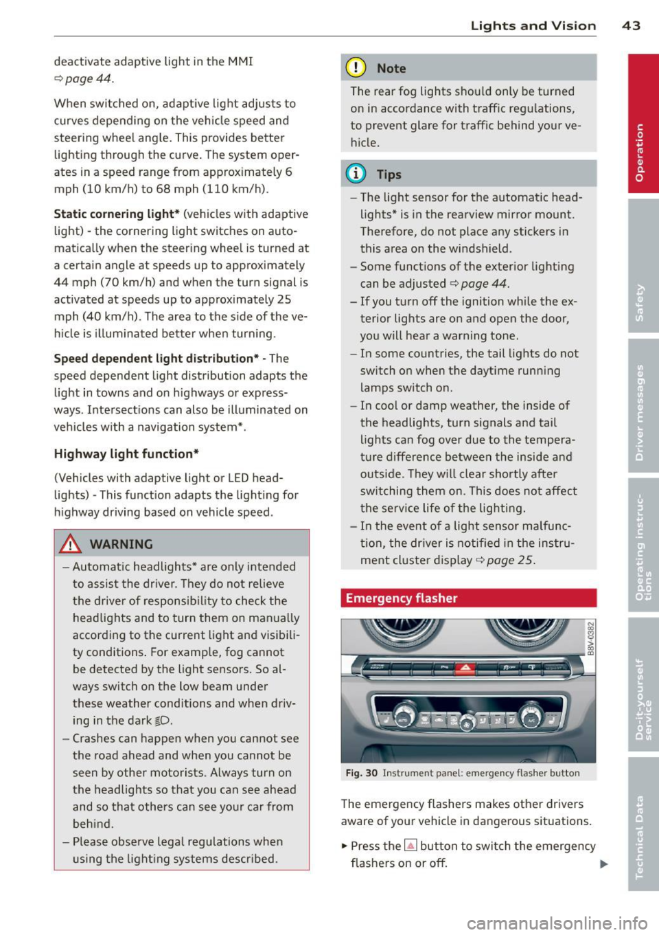
Fig. 30 Ins trume nt panel : emer gency flash er butt on
The emergency flashers makes other dr ivers
aware of your veh icle in dangerous situat ions .
.,. Press the~ but ton to swi tch the emergency
flashe rs on or off.
Ill-
Page 210 of 288
208 Checking and Filling
snow blower, etc., be very careful and al
ways observe local and state laws regard
ing the use, transportation and storage of
such fuel containers . Make certain the con
tainer meets industry standards (ANSI/
ASTM F852 -86) .
(D Note
Never drive your vehicle until the fuel tank
is completely empty . The irregular supply
of fuel can cause misfiring. Gasoline could
enter the exhaust system and damage the
catalytic converter.
Fueling procedure
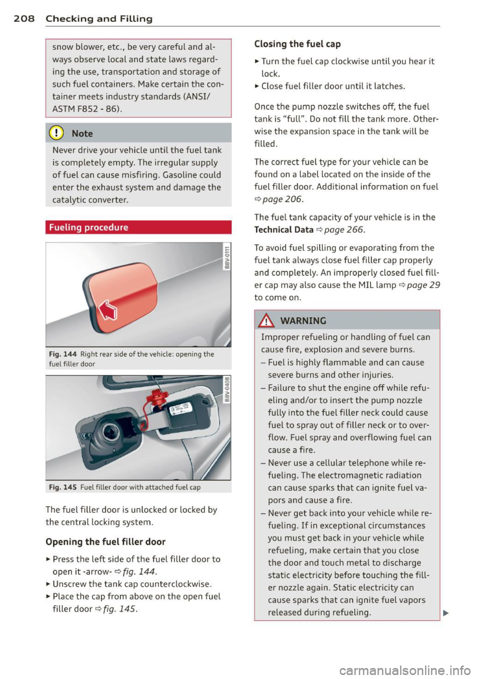
Fig. 144 Rig ht rear side of the vehicle: opening the
fue l filler door
Fig. 145 Fu el filler door w ith atta ched fuel cap
The fuel filler door is unlocked or locked by
the central locking system.
Opening the fuel filler door
.,. Press the left side of the fuel filler door to
open it -arrow-
c::> fig . 144 .
• Unscrew the tank cap counterclockwise.
• Place the cap from above on the open fuel
filler door
c::> fig . 145. Closing the fuel cap
.,.
Turn the fuel cap clockwise until you hear it
lock.
.,. Close fuel filler door until it latches.
Once the pump nozzle switches off , the fuel
tank is "full". Do not fill the tank more. Other
wise the expansion space in the tank will be
filled.
The correct fuel type for your vehicle can be
found on a label located on the inside of the
fuel filler door. Additional information on fuel
c::>page206.
The fuel tank capacity of your vehicle is in the
Technical Data c::> page 266.
To avoid fuel spilling or evaporating from the
fuel tank always close fuel filler cap properly
and completely. An improperly closed fuel fill
er cap may also cause the MIL lamp
c::> page 29
to come on.
A WARNING
Improper refueling or handling of fuel can
cause fire, explosion and severe burns.
- Fuel is highly flammable and can cause
severe burns and other injuries.
- Failure to shut the engine off while refu
eling and/or to insert the pump nozzle
fully into the fuel filler neck could cause
fuel to spray out of filler neck or to
over
flow. Fuel spray and overflowing fuel can
cause a fire .
- Never use a cellular telephone while re
fueling. The electromagnetic radiation can cause sparks that can ignite fuel va
pors and cause a fire .
- Never get back into your vehicle while re
fueling . If in exceptional circumstances
you must get back in your vehicle while
refueling, make certain that you close
the door and touch metal to discharge
static electricity before touching the fill
er nozzle again. Static electricity can
cause sparks that can ignite fuel vapors released during refueling .
Page 224 of 288
222 Checking and Fill in g
and then the negative cable . Never inter
change the cables -this could start a fire!
- Never charge a frozen or a thawed-out
battery. It could explode! If a battery has
frozen, then it must be replaced. A dead battery can freeze over at 32°F (0°C).
- Make sure the vent hose is always attach
ed to the opening on the side of the bat
tery.
- Never use batteries which are damaged.
There is the danger of an explosion! Al
ways replace a damaged battery.
&_ WARNING
California Propos ition 65 Warning:
- Battery posts, terminals and related ac
cessories contain lead and lead com
pounds, chemicals known to the State of
California to cause cancer and reproduc
t ive p roblems. Wash hands after han
dling.
(D Note
- Do not d isconnect t he veh icle battery
when the ignition is on or when the en
gine is running, otherwise, you will dam
age ele ctron ic componen ts in the elec tri
ca l system.
- If your vehicle is going to stand for a
l ong period of time wi thout being driven,
protect the battery from "freezing", oth
e rwise it w ill be damaged and wi ll then
have to be replaced.
Battery charging
Starting the engine requires a well charged battery.
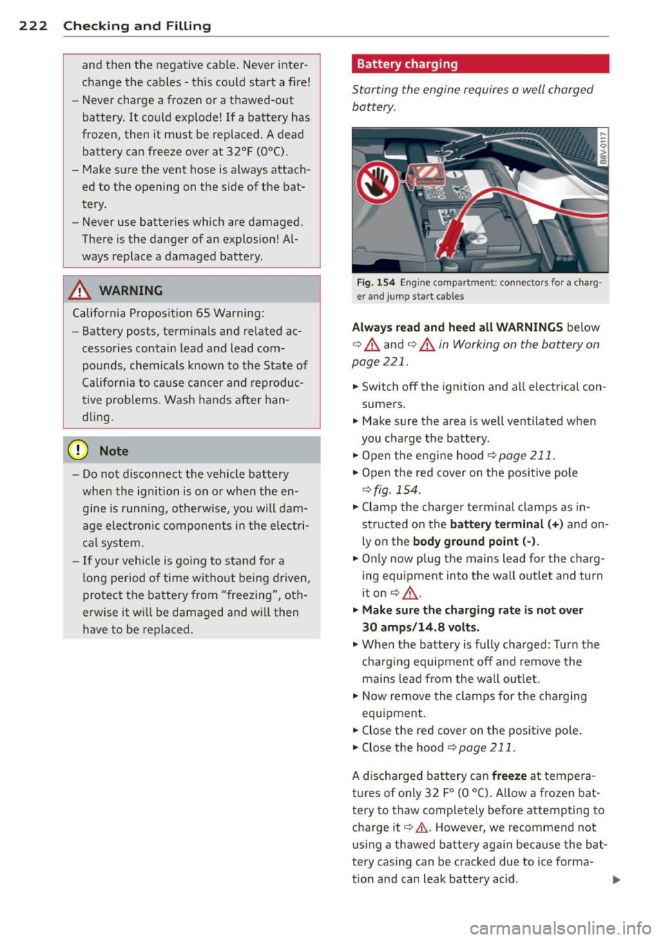
F ig . 1 54 Engine co mpartment : connectors for a charg
er and jump start cab les
Alwa ys read and heed all WARNINGS below
c> &. and c> &. in Working on the battery on
page 221.
.. Switch off the ignition and all electrical con
sumers.
.. Make sure the area is well ventilated when
you charge the battery .
.. Open the eng ine hood
r=;, page 211 .
.. Open the red cover on t he positive pole
r=;, fig. 154 .
.. Clamp the ch arger term inal clamps as in
structed on the
batter y terminal (+ ) and on
ly o n the
body ground po int (-) .
.. On ly now plug the mains lead for the charg
ing equ ipment into the wa ll outlet and turn
iton
c> &, .
.. Make sure th e charging rate is not over
30 amps /14 .8 volts .
.. When the battery is fully charged: Turn the
charg ing equipment off and remove the
mains lead from the wall ou tlet .
.. Now remove the clamps for the cha rging
equipment .
.. Close the red cover on the positive pole .
.. Close the hood
~ page 211.
A d ischarged bat tery can freeze at tempera
tu res of only 32 F
0 (0 °C). Allow a frozen bat
tery to thaw completely before attempting to charge it
r=;, .&, . However, we recommend not
using a thawed battery again because the bat
te ry casing can be cracked due to ice forma-
t ion and can leak battery acid . ..,.
Page 257 of 288
Fuses and bulbs
Electrical fuses
Replacing fuses
Fuses that have blown will have metal strips
that have burned through.
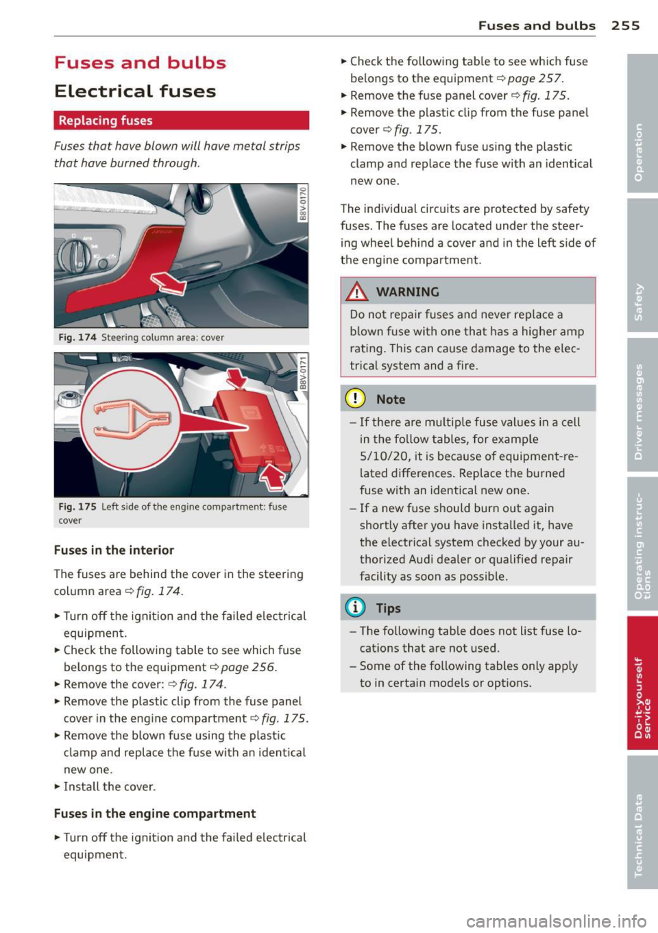
Fig. 17 4 Steering column area: cover
Fig. 175 Left side of the engine compartment: fuse
cover
Fuses i n the interio r
The fuses are behind the cover in the steering
column area
¢fig. 174.
•Turnoff the ignition and the fai led e lectrical
equipment.
• Check the following table to see which fuse
belongs to the equipment¢
page 256.
• Remove the cover: ¢ fig. 174.
• Remove the plastic clip from the fuse panel
cover in the eng ine compartment
c;, fig. 175.
• Remove the blown fuse using the plast ic
clamp and replace the fuse with an ident ica l
new one.
• Install the cover .
Fuse s in th e en gine compar tmen t
•Turnoff the ignition and the failed electrical
equipment .
Fuse s and bulb s 255
• Check the fo llowing tab le to see which fuse
be longs to the equipment
c:;, page 257.
• Remove the fuse panel cover¢ fig. 175.
• Remove the plastic clip from the fuse pane l
cover
c;, fig. 175.
• Remove the blown fuse using the plastic
clamp and replace the fuse with an identical
new one .
The indiv idual circu its are protected by safety
fuses . The fuses are located under the steer
ing wheel beh ind a cover and in the left s ide of
the engine compartment .
.&_ WARNING
-
Do not repair fuses and never replace a
blown f use with one that has a hig her amp
rating. Th is can cause damage to the elec
trica l system and a fire .
(D Note
-If there a re multiple fuse values in a cell
in the fo llow tables, for examp le
5/10/20, it is because of equipment -re
lated differences . Replace the burned
fuse with an identical new one.
- If a new f use should burn out again
shortly after you have installed it, have
the electrical system checked by your au
thorized Aud i dealer or qualified repair
facility as soon as possible.
(!) Tips
- The following tab le does not list fuse lo
cations that are not used .
- Some of the following tables on ly app ly
to in certain models or options.
Page 260 of 288

258 Fuses a nd bul bs
Bulbs
Replacing light bulbs
For your safety, we recommend that you have
your authorized Audi dealer replace burned
out bulbs for you .
It is becoming increasingly more and more
difficult to replace vehicle light bulbs since in
many cases, other parts of the car must first
be removed before you are able to get to the
bu lb . T his appl ies especia lly to the l ight bu lbs
in the front of your car which you can on ly
reach through the engine compartment .
Sheet metal and bulb ho lders can have sharp
edges that can cause ser ious cuts, and parts
must be correctly taken apart and then prop
e rly put back together to help prevent break
age of parts and long term damage from wa
ter that can enter housings that have not been properly resealed.
F or your safety, we recommend that you have
your authorized Audi dealer replace any bulbs
for you, since your dealer has the proper tools,
the correct bu lbs and the expertise.
Gas disc harg e lam ps (X enon lig ht s):
Due to the high electrical vo ltage, have the
bu lbs rep laced by a qualified technician.
H eadlights with Xenon light can be identified
by the high voltage sticker.
LED headlights* require no ma intenance .
P lease contact your authorized Aud i dealer if a
bu lb needs to be replaced.
A WARNING
Contact with high-voltage components of
the electrical system and improper re placement of gas discharge (Xenon) head
light bulbs can cause serious personal in
jury and death .
- Xenon bulbs are pressurized and can ex
plode when being changed.
- Changing Xenon lamps requires the spe
cial training, instruct ions and equ ip
ment. -
On ly an authorized A udi dealer or other
qualified workshop should change the
bulbs in gas discharge lamps .
A WARNING
There are parts with sharp edges on the
openings and on the bulb holders that can
cause serious cuts.
- If you are uncertain about what to do,
have the work performed by an author
ized Audi dealer or other qualified work
shop. Serious personal injury may result
from imprope rly performed work.
(D Tips
- If you st ill prefer to replace the light
bulbs yourself, be aware that the engine
compartment is a hazardous area to
work in
~ page 21 a ~ .11::..
- It is best to ask your authorized Audi
dea ler whenever you need to change a
bulb.
-
Page 261 of 288
Emergency situations
General
This chapter is intended for trained emer
gency crews and working personnel who have the necessary tools and equipment to
perform these operations.
Starting by pushing or
towing
(D Note
Vehicles with an automatic transmission
cannot be started by pushing or towing.
Starting with jumper
cables
If necessary, the engine can be started by
connecting it to the battery of another vehi
cle.
If the engine should fail to start because of a
discharged or weak battery, the battery can be
connected to the battery of
another vehicle,
using a
pair of jumper cables to start the en
gine.
Jumper cables
Use only jumper cables of sufficiently large
cross section to carry the starter current safe
ly. Refer to the manufacturer's specifications.
Use only jumper cables with
insulated termi
nal clamps which are distinctly marked :
plus(+) cable in most cases colored red
minus(-) cable
in most cases colored black.
A WARNING
Batteries contain electricity, acid, and gas.
Any of these can cause very serious or fatal
injury. Follow the instructions below for
safe handling of your vehicle's battery.
- Always shield your eyes and avoid lean
ing over the battery whenever possible.
- A discharged battery can freeze at tem
peratures just below 32 °F (0 °C). Before
Emergency situations 259
connecting a jumper cable, you must
thaw the frozen battery completely, oth
erwise it could explode.
- Do not allow battery acid to contact eyes
or skin. Flush any contacted area with
water immediately .
- Improper use of a booster battery to start a vehicle may cause an explosion.
- Vehicle batteries generate explosive gas
es. Keep sparks, flame and lighted ciga
rettes away from batteries.
- Do not try to jump start any vehicle with a low acid level in the battery.
- The voltage of the booster battery must
also have a 12-volt rating. The capacity
(Ah) of the booster battery should not be
lower than that of the discharged bat
tery . Use of batteries of different voltage
or substantially different "Ah" rating
may cause an explosion and personal in
JU ry.
- Never charge a frozen battery. Gas trap
ped in the ice may cause an explosion.
-Never charge or use a battery that has
been frozen. The battery case may have
be weakened.
- Use of batteries of different voltage or
substantially different capacity (Ah) rat
ing may cause an explosion and injury.
The capacity (Ah) of the booster battery
should not be lower than that of the dis
charged battery.
- Before you check anything in the engine
compartment, always read and heed all
WARNINGS
¢ page 210.
(D Note
-Applying a higher voltage booster bat
tery will cause expensive damage to sen
sitive electronic components, such as
control units, relays, radio, etc.
- There must be no electrical contact be
tween the vehicles as otherwise current
could already start to flow as soon as the
positive(+) terminals are connected. ..,. •
•
•